
Related Manuals for Agilent Technologies 1141A


Summary of Contents for Agilent Technologies 1141A
- Page 1 Agilent 1141A Differential Probe and 1142A Probe Control and Power Module User’s Guide and Service Guide Agilent Technologies...
- Page 2 Earth terminal symbol: Used to indi- "Commercial computer software" as cate a circuit common connected to © Agilent Technologies, Inc. 2000 – 2014 defined in DFAR 252.227-7014 (June 1995), grounded chassis. No part of this manual may be reproduced in or as a "commercial item"...
-
Page 3: Table Of Contents
Gain Accuracy 10x Attenuator Accuracy Test 100x Attenuator Accuracy Test Bandwidth CMRR Test Calibration Test Record Adjusting the Probe Probe Adjustment Attenuator Adapter Adjustment Service Theory of Operation Troubleshooting Removing and Replacing Assemblies Replaceable Parts 1141A and 1142A User’s Guide... - Page 4 Contents 1141A and 1142A User’s Guide...
- Page 5 Each of the two instrument models that make up the differential probe system has a serial number sticker. The sticker for the 1141A Differential Probe is inside the probe, in the bottom cover. (Refer to Chapter 4, “Service”...
-
Page 6: Operating The Probe Introduction
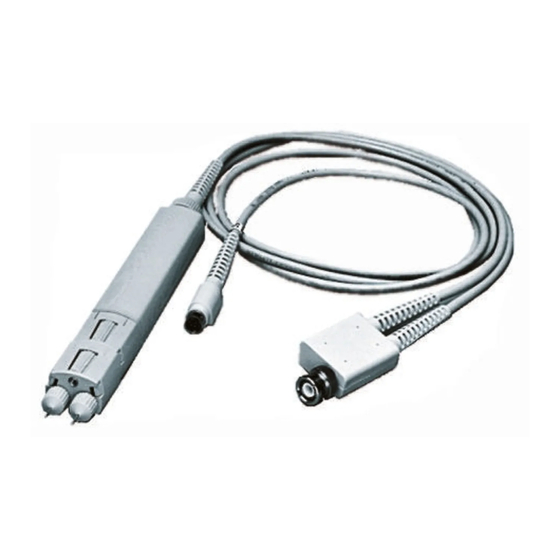
Operating the Probe Introduction Introduction The 1141A probe with the 1142A Probe Control and Power Module allows measurement of small differential signals in the presence of much larger common- mode signals. It has the following major features: ■ 200 MHz bandwidth ■... - Page 7 Two-inch Extension Leads 5959-9334 Power Cord see parts (package 5) list Mini Grabbers 1400-1422 Carrying case Five-inch Ground Lead 5061-6162 User and Service Manual Shielded Signal Lead 01141-6870 Figure 2 1141A Differential Probe and Accessories 1141A and 1142A User’s Guide...
- Page 8 Agilent Technologies office. If the shipping container is damaged, or the cushioning materials show sign of stress, notify the carrier as well as the nearest Agilent Technologies office. Keep the shipping materials for the carrier’s inspection. The office will arrange for repair or replacement at Agilent Technologies’...
- Page 9 Type N (f) to BNC (m) 1250-0077 Adapters (2) BNC (f) to dual banana (m) 1251-2277 Alignment tool Small flat blade (supplied accessory) 8710-1961/ Sprague-Goodman part number GTT-5G a P = calibration tests. A = adjustments 1141A and 1142A User’s Guide...
-
Page 10: Safety Information
WARNING Do not install substitute parts or perform any unauthorized modification to the instrument. WARNING Capacitors inside the instrument may retain a charge even if the instrument is disconnected from its source of supply. 1141A and 1142A User’s Guide... -
Page 11: To Set Up The Probe
NOTE The 1141A/1142A probe system (specifically the 1142A) requires a power source of either 115/230 Vac, 47 to 440 Hz, 25 VA maximum. CAUTION Before connecting power to this instrument, be sure the line voltage switch on the instrument’s rear panel is properly set as described in this section. - Page 12 While the fuse holder is pushed in, gently turn the fuse holder counterclockwise. Connect the 1141A probe cable power connector to the 1142A’s rear- panel PROBE connector. Connect the output of the probe to the input of the oscilloscope.
-
Page 13: To Adjust Offset Null And Dc Reject Gain
To Adjust Offset Null and DC Reject Gain To Adjust Offset Null and DC Reject Gain For a given combination of 1141A Differential Probe and 1142A Probe Control and Power Module, you can adjust the Offset Null and DC Reject Gain. Typically, you need to make these adjustments only once, before the probe is first used. - Page 14 BNC cable between the supply and the test board. Warm up the 1141A for 30 minutes before making adjustments. With the 1141A probe inputs unconnected, adjust Offset Null on the 1142A for a minimum reading on the DVM. The voltage swing of the adjustment is approximately ±4 mV.
-
Page 15: Using The Accessories
Operating the Probe Using the Accessories Using the Accessories The 1141A Differential Probe and accessories are designed to provide a variety of ways to connect to circuitry and make measurements. In the descriptions, any method used to connect to the probe signal inputs also applied to the adapters. - Page 16 CMRR is particularly sensitive to unbalanced input parameters. To prevent pickup of stray fields when you use extension lead, either the ones supplied with the 1141A or others, dress them carefully as follows: ■...
- Page 17 A snug fit is important because the ground is maintained through the thumb wheel screw. A loosely attached adapter compromises the mechanical and electrical integrity of the combination. Figure 7 Attaching the Adapters 1141A and 1142A User’s Guide...
- Page 18 Test Board The primary use of the test board is to apply test and calibration signals to the input of the probe or adapters. Specific use of the test board is covered wherever it applies. 1141A and 1142A User’s Guide...
- Page 19 Operating the Probe Using the Accessories Figure 8 Allowed Adapter Connections 1141A and 1142A User’s Guide...
-
Page 20: Grounding
The screw where the ground lead attaches fastens to this ground. Figure 9. Also, the attenuator and ac adapter fasten to this ground through the screw connection and the ground is carried through each adapter to its front. Figure 9 Probe Grounds 1141A and 1142A User’s Guide... -
Page 21: Coupling Functions
The voltage reject range is ±20V with the probe alone, ±200V with the 10x attenuator, and ±500V with the 100x attenuator. To use dc reject: Remove the ac adapter if it is installed. On the front panel of the 1142A, press Local. 1141A and 1142A User’s Guide... - Page 22 When the ac adapter is on an attenuator the corner is 1.5 Hz. ■ The low- frequency CMRR when using the ac adapter is not as good as when using the probe alone or the probe with a 10x or 100x adapter. 1141A and 1142A User’s Guide...
-
Page 23: Remote Operation
The following truth table shows the functions provided by the function select lines. For the Remote Inputs, “0” represents a closure and “1” represents an open circuit. 1141A and 1142A User’s Guide... - Page 24 Table 5 Remote Offset Input Requirements Remote Offset Range Requirements Probe alone ± 20V ± 10V Probe with 10x adapter ± 200V ± 10V Probe with 100x adapter ± 500V ± 2.5V 1141A and 1142A User’s Guide...
-
Page 25: Differential Amplifiers And Cmrr
Also, stray coupling increases with frequency and coupling may vary between the two differential paths. The CMRR of the 1141A Differential Probe is specified at the input of the probe and cannot be affected expect by adjustments in the probe. However, the way the probe is connected into the circuitry being tested can have a big influence in the overall result of the measurement, especially at high frequencies. - Page 26 (the ac adapter is being used) the CMRR will be degraded below a certain frequency; the lower the frequency the worse the CMRR. This is because unbalance in the series capacitances of the ac coupler becomes more significant the lower the frequency. 1141A and 1142A User’s Guide...
-
Page 27: Calibrating The Probe
100x Attenuator Accuracy Test Bandwidth CMRR Test Calibration Test Record This chapter provides the calibration tests for the 1141A Differential Probe and 1142A Probe Control and Power Module. These procedures test the probe’s electrical performance using applicable specifications given in Chapter 4, “Specifications and... -
Page 28: 2 Calibrating The Probe
Calibration Test Procedures Procedures may be done individually or in any order. NOTE Allow the instrument to warm up for at least 30 minutes prior to beginning calibration tests. 1141A and 1142A User’s Guide... -
Page 29: Dc Gain Accuracy
Local/Remote push button to Local. Under DC Couple, press the Zero offset button. With the 1141A Probe Amp disconnected from the test PCA, adjust the Offset Null control on the 1142A until the DVM reads 0 Vdc. If the probe output voltage cannot be set to 0V, subtract this voltage from the subsequent measurements in this test. - Page 30 Figure out1 Connect the Probe Amp to measure a negative voltage as shown in Figure 12 on page 30. Record the V measurement from the bottom DVM in Figure out2 Figure 12 Signal to –Input 1141A and 1142A User’s Guide...
- Page 31 42. To pass this test, the probe gain = 0.98 to 1.02. NOTE Failure of the gain accuracy test can be caused by mis-adjustment of the probe. Perform the Probe Adjustment procedure in the Adjustments section later in this chapter and retest. 1141A and 1142A User’s Guide...
-
Page 32: 10X Attenuator Accuracy Test
Carefully connect the input of the probe/attenuator to the test board in the position shown in Figure Figure 14 Signal to –Input Record the V measurement from the bottom DVM in Figure 11 out2 on page 30. Calculate the 10x attenuator gain as 1141A and 1142A User’s Guide... - Page 33 CMRR (LF CMRR) adjustment. Perform the Attenuator Adapter Adjustment procedure in the Adjustments section later in this chapter then retest the attenuator adapter. If if continues to fail, repair is necessary. 1141A and 1142A User’s Guide...
-
Page 34: 100X Attenuator Accuracy Test
DVM in Figure 11 out1 on page 30. Carefully connect the input of the probe/attenuator to the test board in the position shown in Figure 16 on page 34. Figure 16 Signal to –Input 1141A and 1142A User’s Guide... - Page 35 CMRR (LF CMRR) adjustment. Perform the Attenuator Adapter Adjustment procedure in the Adjustments section later in this chapter then retest the attenuator adapter. If if continues to fail, repair is necessary. 1141A and 1142A User’s Guide...
-
Page 36: Bandwidth
Calibrating the Probe Bandwidth Bandwidth This test checks the high- frequency response of the 1141A Differential Probe. The bandwidth of the oscilloscope is characterized first so it is not a factor in the measurement. This test depends on the accuracy of the termination on the test board and the termination in the oscilloscope. - Page 37 Change the signal generator output level and oscilloscope V/div range proportionally. NOTE Failure of the bandwidth test can be caused by mis-adjustment of the probe. Perform the Probe Adjustment procedure in the Adjustments section later in this chapter. 1141A and 1142A User’s Guide...
-
Page 38: Cmrr Test
Signal to +Input Connect the signal generator to the test board. Set the signal generator for 1 MHz at 385 mV (1 V p- p On the oscilloscope, press AUTOSCALE and set the following parameters. 1141A and 1142A User’s Guide... - Page 39 After the measurement settles (averaging is complete), record the V P- P reading. (2) = _____________ mV Disconnect the probe amp from the test board and measure V noise on channel 1. Calculate the CMRR result as follows ------------------------------ - CMRR – noisepp 1141A and 1142A User’s Guide...
- Page 40 After the measurement settles (averaging is complete), not the V P- P reading. (2) = _____________ mV Disconnect the probe amp from the test board and measure V noise on channel 1. Calculate the CMRR result as follows: 1141A and 1142A User’s Guide...
- Page 41 ------------------------------ - CMRR – noisepp Record the result of this calculation in the “Calibration Test should be ≥ 10, Record” on page 42. The result in step 21 representing a CMRR of 10:1 or more. 1141A and 1142A User’s Guide...
-
Page 42: Calibration Test Record
Gain Accuracy Probe Only +0.98 mV to +1.02 mV +0.096 mV to +0.104 mV 100x +0.0096 mV to 0.0104 mV > 0.707 at 200 MHz Bandwidth CMRR ≥ 3000:1 1 MHz ≥ 10:1 100 MHz 1141A and 1142A User’s Guide... -
Page 43: Adjusting The Probe
Step 3. Adjust the Low Frequency Response and CMRR Step 4. Adjust the High Frequency Compensation Attenuator Adapter Adjustment This chapter provides the adjustment procedures for the 1141A Differential Probe and 1142A Probe Control and Power Module. None of the adjustment procedures that follow should be considered for a routine maintenance plan. -
Page 44: 3 Adjusting The Probe
At each position of the probe or A1 PC assembly, probe inputs are connected to a different combination of signal and ground. A separate terminal on the test board connects the ground of the probe to the signal ground. Figure 22 Test Board Showing Probe Positions 1141A and 1142A User’s Guide... -
Page 45: Probe Adjustment
Adjusting the Probe Probe Adjustment Probe Adjustment This procedure adjust the high- frequency and low- frequency paths on the 1141A Differential Probe. Table 11 shows the equipment required for this procedure. Procedures are based on the model or part number recommended. - Page 46 As shown in Figure 23 on page 46, use the grounding screw to reinstall the ground block on the A1 PC assembly. Figure 23 Attaching Ground Block to Probe A1 PC Assembly 1141A and 1142A User’s Guide...
-
Page 47: Step 2. Adjust The Hf Gain And Hf Cmrr
(1) = _____________ mV Disconnect the BNC cable from the channel 1 input and connect it to the BNC connector on the test board. Connect the output of the probe to the channel 1 input. 1141A and 1142A User’s Guide... - Page 48 Press CLEAR DISPLAY occasionally to restart averaging, which gives a quicker indication of changes. Carefully connect the probe to the test board in the position shown Figure 1141A and 1142A User’s Guide...
-
Page 49: Step 3. Adjust The Low Frequency Response And Cmrr
Change the oscilloscope settings to: Table 13 Oscilloscope Settings Menu Selection Setting TIMEBASE (time/div) 50 µs/div CHAN 1 (sensitivity) 100 mV/div Carefully connect the input of the probe to the test board in the position shown in Figure 1141A and 1142A User’s Guide... - Page 50 CLEAR DISPLAY frequently to restart averaging. Figure 28 R14 and C4 Adjustment Carefully connect the probe to the test board in position shown in the figure below (signal to both inputs). Signal to Both Inputs 1141A and 1142A User’s Guide...
-
Page 51: Step 4. Adjust The High Frequency Compensation
Adjust R13 (HF COMP) to make the signal amplitude measurement on the oscilloscope 300 mV , or as close to that as possible. p- p Adjust slowly and press CLEAR DISPLAY frequently to restart averaging. 1141A and 1142A User’s Guide... - Page 52 The side of the PC assembly with the large hybrid is exposed when the assembly is in the top cover. The figure below shows how the top cover, PC board, and ground block fit together. 1141A and 1142A User’s Guide...
- Page 53 Insert the pins at the front of the bottom cover into the holes at the front of the top cover. Close the two covers together and fasten with the probe clamp ring. 1141A and 1142A User’s Guide...
-
Page 54: Attenuator Adapter Adjustment
An adapter will need adjustment only if one or more of the following occurs. ■ If an adapter is to be used on a different 1141A probe that it was calibrated with last. ■... - Page 55 Adjustment Procedure NOTE The attenuator must be adjusted when installed on the 1141A probe with which it will be used. The specifications and characteristics will not be met if the attenuator adapter is adjusted with one differential probe then used with another.
- Page 56 Connect the adapter/probe combination to the test board in the position shown in Figure Figure 32 Signal to +Input Adjust the + HF RESP for best overall pulse response, the flattest pulse top. Use the figure below for adjust locations. Figure 33 Adjustment Locations 1141A and 1142A User’s Guide...
- Page 57 Each adjustment should be set to minimize the component of the signal it affects most. Some high- frequency components of the signal are not affected by either adjustment. 1141A and 1142A User’s Guide...
- Page 58 Adjusting the Probe Attenuator Adapter Adjustment 1141A and 1142A User’s Guide...
-
Page 59: Service
For complex parts, the service policy is for assembly- level repair. For parts with simple circuitry, the service policy is component- level repair. The service policy for the 1141A is assembly- level repair. Assemblies include the cable and the PC assembly, which is an exchange assembly (a repaired and tested assembly is shipped upon receipt of the defective assembly). -
Page 60: Theory Of Operation
(Figure 35 on page 62). The differential probe system consists of two units, the 1141A Differential Probe with its accessories and the 1142A Probe Control and Power Module. For purposes of the following discussion, these will be called the probe and the control module respectively. - Page 61 Summing Amp The summing amp combines the feedback signal, the low- frequency signal, and the offset signal. The LOW FREQ GAIN adjustment matches the gain of the low- frequency path to the overall gain. 1141A and 1142A User’s Guide...
- Page 62 Service Theory of Operation Figure 35 1141A Differential Probe System Block Diagram 1142A Control and Power The control and power module provides offset functions, local and Module remote control, and power to the probe system. 1141A and 1142A User’s Guide...
- Page 63 The high- frequency adjustments are the same for each attenuator. Each attenuator is adjusted differently. One attenuator is adjusted for optimum pulse response and the other for best high- frequency CMRR. 1141A and 1142A User’s Guide...
- Page 64 The test board is a device for conveniently connecting test signals to the differential probe. The probe can be connected to the board with the signal to the positive, negative, or both inputs. Figure 37 Test Board Schematic 1141A and 1142A User’s Guide...
-
Page 65: Troubleshooting
Service Troubleshooting Troubleshooting Use the following paragraphs to assist in troubleshooting problems with the 1141A/1142A Differential Probe. Probe Troubleshooting To troubleshoot the probe: Apply a known signal to the input of the probe. Check for an identical output at the output coax to the cable. This connection is the one soldered to the PC board. - Page 66 Service Troubleshooting Figure 38 1142A Probe Control and Power Module 1141A and 1142A User’s Guide...
-
Page 67: Removing And Replacing Assemblies
PC board fits over the pins in the top cover. Lift the board off of the pins and slide it in the direction of the cable until the input connectors clear the front of the probe. 1141A and 1142A User’s Guide... - Page 68 Reassembling the Probe Insert the input connectors first, and seat the cable end of the PC assembly over the pins at the rear of the cover. Position the ground block at the front of the PC assembly. 1141A and 1142A User’s Guide...
-
Page 69: To Disassemble The Probe Adapters
(the end which attaches to the probe). Note the view of the input end of the adapter in the figure below. The arrows indicate the holding tabs. Figure 40 Disassembling Adapters 1141A and 1142A User’s Guide... - Page 70 Insert the substrate/board into the outer housing. Slip the attenuator ground (attenuator adapters only) over the thumb wheel screw and seat the input connectors in the proper holes in the housing. Figure 41 Reassembling the Adapter 1141A and 1142A User’s Guide...
-
Page 71: To Disassemble 1142A
Remove the two heat sink spacers from the standoffs that were directly under the heat sink. Reverse the procedure to reassemble the control and power supply. 1141A and 1142A User’s Guide... -
Page 72: Replaceable Parts
Replaceable Parts This section contains information for ordering parts. Service support for the 1141A Differential Probe is to the assembly level. Service support for the adapters is as complete assemblies, except for the probe tip caps and the probe tips. Service support for the 1142A Probe Control and Power Module is to the component level. - Page 73 Service Replaceable Parts Mail order forms and specific ordering information are available through your local Agilent Technologies Sales Office. Addresses and telephone numbers are located in a separate document shipped with the manuals. Manufacturers’ Codes A list of manufacturers’ codes is given the table below. The codes are given for parts in the parts lists.
- Page 74 Service Replaceable Parts Figure 42 1141A Differential Probe Parts Identification 1141A and 1142A User’s Guide...
- Page 75 Service Replaceable Parts Figure 43 Power and Control Board Component Identification 1141A and 1142A User’s Guide...
- Page 76 Service Replaceable Parts Figure 44 Cabling Diagram 1141A and 1142A User’s Guide...
- Page 77 Service Replaceable Parts IC Connectors not Shown Supply Pin No. IC Group U6-8, 11 1, 5, 8 Figure 45 1142A Probe Control and Power Module 1141A and 1142A User’s Guide...
- Page 78 Service Replaceable Parts Figure 46 1142A Probe Control and Power Module 1141A and 1142A User’s Guide...
- Page 79 Service Replaceable Parts Table 18 1141A and 1142A Replaceable Parts (Sheet 1 of 2) Ref. Mfr. Des. Part Number Qty Description Code Mfr. Part Number 1141A Differential Probe 01141-66503 PC ASSEMBLY-DIFFERENTIAL PROBE 28480 01141-66501 01141-26102 PROBING PIN 28480 01141-26102 01141-22301...
- Page 80 Service Replaceable Parts Table 18 1141A and 1142A Replaceable Parts (Sheet 2 of 2) Ref. Mfr. Des. Part Number Qty Description Code Mfr. Part Number 0370-1097 KNOB-POINTER 28480 0340-1097 0403-1012 FOOT 28480 0403-0727 5041-0234 KEYCAP 28480 5041-0234 8120-1521 POWER CORD 18-AWG 3-COND 90-IN-LG (US/Canada only) 28480 8120-1521 1141A and 1142A User’s Guide...
- Page 81 0180-3784 0180-3784 CAPACITOR-FXD 22UF ±20% 25VDC TA 28480 0180-3784 0180-3784 CAPACITOR-FXD 22UF ±20% 25VDC TA 28480 0180-3784 NOT ASSIGNED 1901-1087 DIODE-PWR RECT 100V 3A 04713 MR501 1901-1087 DIODE-PWR RECT 100V 3A 04713 MR501 NOT ASSIGNED 1141A and 1142A User’s Guide...
- Page 82 0361-0685 RIVET-BLIND DR-PIN RNDH 0.125DIA 28480 0361-0685 0340-1211 INSULATOR-THERMAL 28480 0340-1211 MP5-6 NOT ASSIGNED 1400-0249 CABLE TIE 0.062-0.625-DIA 0.091-WD NYL 16956 08-465/GRY 01142-24702 TRANSFORMER SUPPORT 28480 01142-24702 01142-28801 WASHER-TRANSFORMER SUPPORT 28480 01142-28801 R1-2 NOT ASSIGNED 1141A and 1142A User’s Guide...
- Page 83 RESISTOR 10K 1% 0.125W TF TC=0±100 24546 CT4-1/8-TO-1002-F 0757-0442 RESISTOR 10K 1% 0.125W TF TC=0±100 24546 CT4-1/8-TO-1002-F 0757-0280 RESISTOR 1K 1% 0.125W TF TC=0±100 24546 CT4-1/8-TO-1001-F 0757-0460 RESISTOR 61.9K 1% 0.125W TF TC=0±100 24546 CT4-1/8-TO-6192-F 1141A and 1142A User’s Guide...
- Page 84 04713 MC74HC157N 1826-0774 IC V RGLTR-V-REF-FXD 1.22/1.24V TO-92 27014 LM385BZ-1.2 1826-0635 IC OP AMP LOW-OFS 8-DIP-P PKG 06665 OP-07CP 1902-0951 DIODE-ZNR 5.1V 5% D0-35 PD=.4W TC±.035% 28480 1902-0951 01141-61602 CABLE ASSEMBLY, SAFETY GROUND 28480 01141-61602 1141A and 1142A User’s Guide...
- Page 85 Replaceable Parts Table 20 Locater Table for Control and Power Supply Ref. Grid Grid Grid Grid Grid Grid Grid Grid Des. CR10 C-5 CR11 C-3 CR12 C-6 CR13 C-3 CR14 C-6 CR17 B-5 CR18 B-6 1141A and 1142A User’s Guide...
- Page 86 Service Replaceable Parts 1141A and 1142A User’s Guide...
- Page 87 1141A and 1142A User’s Guide...
- Page 88 & power module, 66, probe control & power module, service policy, 1141A and 1142A User’s Guide...