Table of Contents
Advertisement
Quick Links
TM
INSTALLATION MANUAL
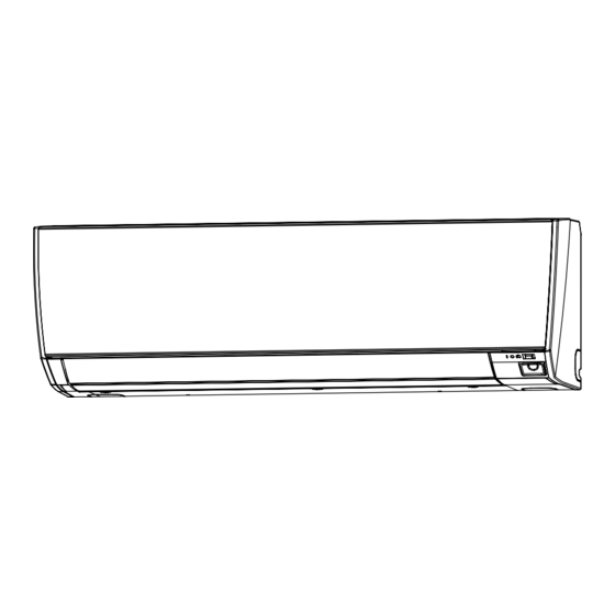
INDOOR UNIT (Wall Mounted Type)
For authorized service personnel only.
MANUEL D'INSTALLATION
UNITÉ INTÉRIEURE (Type montage mural)
Pour le personnel agréé uniquement.
MANUAL DE INSTALACIÓN
ASUA4TLAV2
UNIDAD INTERIOR (Tipo montado en pared)
ASUA7TLAV2
Únicamente para personal de servicio autorizado.
ASUA9TLAV2
ASUA12TLAV2
ASUA14TLAV2
PART No. 9373370499
Advertisement
Table of Contents

Related Manuals for Fujitsu Airstage ASUA4TLAV2


Summary of Contents for Fujitsu Airstage ASUA4TLAV2
- Page 1 INSTALLATION MANUAL INDOOR UNIT (Wall Mounted Type) For authorized service personnel only. MANUEL D’INSTALLATION UNITÉ INTÉRIEURE (Type montage mural) Pour le personnel agréé uniquement. MANUAL DE INSTALACIÓN ASUA4TLAV2 UNIDAD INTERIOR (Tipo montado en pared) ASUA7TLAV2 Únicamente para personal de servicio autorizado. ASUA9TLAV2 ASUA12TLAV2 ASUA14TLAV2...
-
Page 2: Table Of Contents
INSTALLATION MANUAL 1.2. SPECIAL PRECAUTIONS PART No. 9373370499 VRF system indoor unit (Wall mounted type) When Wiring ELECTRICAL SHOCK CAN CAUSE SEVERE PERSONAL INJURY OR DEATH. Contents ONLY A QUALIFIED, EXPERIENCED ELECTRICIAN SHOULD ATTEMPT TO WIRE SAFETY PRECAUTIONS ................... 1 THIS SYSTEM. -
Page 3: About This Product
Name and Shape Q’ty Application 2. ABOUT THIS PRODUCT Air cleaning filter For installation, refer to the “CLEANING AND CARE” in the operating manual. 2.1. Precautions for using R410A refrigerant Air cleaning filter frame WARNING Do not introduce any substance other than the prescribed refrigerant into the refrigera- tion cycle. -
Page 4: Installation Dimension
Detection range of the human sensor (1) Fasten the wall hook Wall hook bracket bracket to the wall with 5 or more screws and CAUTION anchor bolts through Do not hit or push the human sensor. This may lead to damage or malfunction. the holes near the outer edge of the bracket. -
Page 5: Pipe Installation
[For (D) Left bottom piping, (E) Left piping and (F) Left rear piping] 4.1. Selecting the pipe material CAUTION CAUTION Insert the drain hose and drain cap into the drain port, making sure that it comes in con- Do not use existing pipes from another refrigeration system or refrigerant. tact with the back of the drain port, and then mount it. -
Page 6: Electrical Wiring
When using conventional (R22) flare tools to flare R410A pipes, the dimension A should Install the remote controller cables so as not to be direct touched with your hand. be approximately 0.02 in (0.5 mm) more than indicated in the table (for flaring with R410A Perform wiring work in accordance with standards so that the air conditioner can be flare tools) to achieve the specified flaring. -
Page 7: Wiring Method
B. For strand wiring 5.2. Wiring method (1) Use ring terminals with insulating sleeves as shown in the figure below to connect to Example the terminal block. (2) Securely clamp the ring terminals to the cables using an appropriate tool so that the Outdoor unit or RB unit *1 Breaker 1: Ground Fault Equipment cables do not come loose. -
Page 8: Wiring
Name Application 5.4. Wiring CNA01 Apply voltage terminal For external input (1) Open the intake grille. Refer to “8. FRONT CNA03 PANEL REMOVAL AND INSTALLATION”. CNA02 Dry contact terminal (2) Remove the wire cover. CNA04 (3) Connect the end of the connection cable DIP switch SET 2 (SW2) Input signal type switching fully into the terminal block. -
Page 9: External Input And External Output (Optional Parts)
When connected to Dry contact terminals of multiple indoor units with a connected unit, 5.6. External input and external output (Optional parts) insulate each indoor unit with relay, etc. as shown on below example. 5.6.1 External input P.C.B • Indoor unit can be Operation/Stop, Emergency stop or Forced stop by using indoor unit PCB CNA01 or CNA02. -
Page 10: Field Setting
● Forced thermostat off function 6. FIELD SETTING [“Edge” input only] There are 3 methods for address setting by FIELD SETTING as follows. Connector Input signal Command Please set by either of the methods. OFF → ON Thermostat off Each setting method is described in below (1) to (3). Ch3 of CNA03 or CNA04 ON →... -
Page 11: Custom Code Setting
Table A Function details Address Rotary Switch Setting Address Rotary Switch Setting Function Function Setting number Default Details REF AD SW IU AD SW number Refrigerant circuit Indoor unit × 10 × 1 × 10 × 1 Adjust the filter cleaning interval 00 Standard notification. - Page 12 Function 00 Disable Function Setting number Default Details Emergency Enables or disable of emer- number heat gency heat input. 01 Enable Auxiliary heater con- 00 1 minutes trol 1 01 50 seconds Fan delay Sets the fan delay time when Auxiliary time the heater is turned off.
-
Page 13: Finishing
• Refrigerant address example • Bind the connection cable with Connection cable (Power supply cable) vinyl tape. (Example) ADDRESS : 30 • Bundle the piping and drain hose 1 cycle 12 sec together by wrapping them with cloth tape over the range within OPERATION indicator Pipe 1.0s... -
Page 14: Front Panel Installation
8.3. Front panel installation 11. ERROR CODES If you use a wired type remote controller, error codes will appear on the remote controller (1) First, fit the lower part of the front panel, and insert top and bottom hooks. (3 top display.