Planet POE-1200G User Manual
12-/24-port gigabit 802.3at poe+ managed injector hub
Hide thumbs
Also See for POE-1200G:
- User manual (57 pages) ,
- Quick installation manual (2 pages) ,
- User manual (61 pages)

Related Manuals for Planet POE-1200G


Summary of Contents for Planet POE-1200G
- Page 1 12-/24-Port Gigabit 802.3at PoE+ Managed Injector Hub POE-1200G/POE-2400G/ HPOE-1200G/HPOE-2400G...
- Page 2 Information in this User's Manual is subject to change without notice and does not represent a commitment on the part of PLANET. PLANET assumes no responsibility for any inaccuracies that may be contained in this User's Manual. PLANET makes no c ommitment to update or keep current the information in this User's Manual, and reserves the right to make improvements to this User's Manual and/or to the products described in this User's Manual, at any time without notice.
-
Page 3: Table Of Contents
2.2.4 Power over Ethernet Powered Device………………………………………..22 3. Preparation………………………………………………………………………….....23 3.1 System Requirements……………………………………………………………………..23 3.2 Management Method …………………………………………………………………………...23 3.2.1 Web Management………………………………………………………..…………..23 3.2.2 PLANET Smart Discovery Utility……………………………………………...25 3.3 Starting Setup in the Web UI…………………………………………………………..……….27 4.Web-based Management……………………………………………………………………..28 4.1 System…………………………………………………………………………………………..29 4.1.1 System Information .....................30 4.1.2 System Service ....................31 4.1.3 Connection Status………………………………………..………………….…...32... - Page 4 4.4.3 PoE Schedule ....................49 4.4.4 PoE Alive Check ....................51 4.5 Maintenance…………………………………………………………………………………….53 4.5.1 Administrator ....................54 4.5.2 Date and Time ....................54 4.5.3 Saving/Restoring Configuration ............... 55 4.5.4 Firmware Upgrading ..................56 4.5.5 Reboot/Reset ....................57 4.5.6 Auto Reboot ..................... 57 4.5.7 Diagnostics ......................
-
Page 5: Introduction
1. Introduction Thank you for purchasing PLANET 12-/24-Port Gigabit IEEE 802.3at PoE+ Managed Injector Hub, POE-1200G, POE-2400G, HPOE-1200G or HPOE-2400G. The descriptions of these models are as follows: 12-Port Gigabit IEEE 802.3at PoE+ Managed Injector Hub (220 watts) POE-1200G 24-Port Gigabit IEEE 802.3at PoE+ Managed Injector Hub (440 watts) POE-2400G 12-Port Gigabit IEEE 802.3at PoE+ Managed Injector Hub (360 watts) -
Page 6: Product Overview
Remote Management Solution PLANET's Universal Network Management System (UNI-NMS) and CloudViewer app support IT staff by remotely managing all network devices and monitoring PDs' operational statuses. Thus, they're designed for both the enterprises and industries where deployments of PDs can be as remote as possible, without having to go to the actual location once a bug or faulty condition is found. - Page 7 Perfect Managed PoE+ Injector Hub with Full Power Budget The PoE+ Managed Injector Hub series features PLANET intelligent functions where remote management can be done through web user interface. It provides 12/24 10/100/1000BASE-T Ethernet ports featuring 802.3at PoE+ injector function with a total PoE budget of 220 to 720 watts. Each PoE port can deliver up to 36-watt power over Cat.5/5e/6 Ethernet UTP cables which allow data and power to transmit simultaneously to...
- Page 8 IEEE 802.3at PoE+ Standard Compliance The PoE in-line power adopting the IEEE 802.3at Power over Ethernet Plus standard makes the PoE+ Managed Injector Hub series able to deliver per port up to 36 watts of power to each remote PoE compliant PD.
- Page 9 Intelligent Powered Device Alive Check PLANET’s Managed PoE products adopt not only Power over Ethernet technology, but also automated PD monitoring and real-time PoE status. The PoE+ Managed Injector Hub series can be configured to monitor connected PD’s status in real time via ping action through the uplinked Ethernet switch. Once the PD stops working and responding, the PoE+ Managed Injector Hub series will recycle the PoE port power and bring the PD back to work.
- Page 10 With 36-watt PoE output capability, the PoE+ Managed Injector Hub series can extend much longer distance by using PLANET PoE Extender for powering up the PoE PD which can be installed over more than 100 meters away. By daisy-chaining multiple PLANET PoE Extenders, it offers the great flexibility of doubling, tripling or quadrupling the distance of PoE network.
-
Page 11: Product Features
System CA certificate for HTTPS Management IPv4 and IPv6 dual stack management Web interface for remote management PLANET DDNS and Easy DDNS Network Time Protocol (NTP) System Maintenance Firmware upload via HTTP −... -
Page 12: Product Specifications
PLANET Smart Discovery utility automatically finds PLANET devices on the network PLANET NMS system and CloudViewer for deployment management SNMP v1, v2c and v3 for system status monitoring SNMP trap for alarm notification of events System event log/remote syslog ... - Page 13 Reset button for system reset to factory default Management Feature PLANET Smart Discovery utility PLANET NMS system and CloudViewer for deployment management SNMP v1, v2c and v3 for system status monitoring SNMP trap for alarm notification of events System event log/remote syslog...
- Page 14 Trace route − Standards Conformance FCC Part 15 Class A, CE Regulatory Compliance IEEE 802.3 10BASE-T Ethernet IEEE 802.3u 100BASE-TX Fast Ethernet IEEE 802.3ab 1000BASE-T Gigabit Ethernet IEEE 802.3at Power over Ethernet Plus IEEE 802.3af Power over Ethernet RFC 768: UDP Standards Compliance RFC 791: IP RFC 2068 HTTP...
-
Page 15: Physical Description
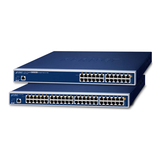
Figure 2-1-1, 2-1-2, 2-1-3 & 2-1-4 show the front panel of the PoE+ Managed Injector Hub. Front Panel of POE-1200G Figure 2-1-1: POE-1200G front panel Front Panel of POE-2400G Figure 2-1-2: POE-2400G front panel Front Panel of HPOE-1200G Figure 2-1-3: HPOE-1200G front panel ... - Page 16 Reset button At the left of the front panel, the reset button is designed for rebooting the PoE+ Managed Injector Hub without turning off and on the power. Figure 2-1-5: Reset Button of PoE+ Managed Injector Hub The following is the summary table of reset button functions: Reset Button Pressed and Released Function...
-
Page 17: Led Indicators
2.1.2 LED Indicators The front panel LEDs indicates instant status of system power, fan, management port Link/Active and PoE port links, thus helping administrator to monitor and troubleshoot when needed. POE-1200G/HPOE-1200G System Color Function Lights to indicate power on. -
Page 18: Injector Rear Panel
100 to 240V AC, 50/60Hz. Figures 2-1-6 & 2-1-7 & 2-1-8 & 2-1-9 show the rear panel of the PoE+ Managed Injector Hub. Figure 2-1-6: POE-1200G Rear Panel Figure 2-1-7: HPOE-1200G Rear Panel Figure 2-1-8: POE-2400G Rear Panel Figure 2-1-9: HPOE-2400G Rear Panel The PoE+ Managed Injector Hub is a power-required device, meaning PoE+ Managed Injector Hub will not work till it is powered. -
Page 19: Installing The Poe+ Managed Injector Hub
This section describes how to install your PoE+ Managed Injector Hub and make connections to the PoE+ Managed Injector Hub. Please read the following topics and perform the procedures in the order being presented. PLANET PoE+ Managed Injector Hub does not need software configuration. 2.2.1 Desktop Installation To install a PoE+ Managed Injector Hub on a desktop or shelf, simply complete the following steps: Step 1: Attach the rubber feet to the recessed areas on the bottom of the PoE+ Managed Injector Hub. -
Page 20: Rack Mounting
2.2.2 Rack Mounting To install the PoE+ Managed Injector Hub in a 19-inch standard rack, follow the instructions described below. Step 1: Place your PoE+ Managed Injector Hub on a hard flat surface, with the front panel positioned towards your front side. Step 2: Attach a rack-mount bracket to each side of the PoE+ Managed Injector Hub with supplied screws attached to the package. -
Page 21: Network Application Installation
2.2.3 Network Application Installation The PoE+ Managed Injector Hub is not an equipment with data switching function between data ports. To inject PoE power and transmit data packets to PDs, the PoE+ Managed Injector Hub is usually linked to an Ethernet switch. -
Page 22: Power Over Ethernet Powered Device
2.2.4 Power over Ethernet Powered Device Voice over IP phones Enterprise can install POE VoIP Phone, ATA and other Ethernet/non-Ethernet end-devices in the central area where UPS is installed for un-interruptible power system and power control 3~5 watts system. Wireless LAN Access Points Museums, sightseeing spots, airports, hotels, campuses, factories, and warehouses can install the Access Point anywhere. -
Page 23: Preparation
3. Preparation Before getting into the device’s web UI, user has to check the network setting and configure PC’s IP address. System Requirements Workstations running Windows XP/2003/2008/2012/Vista/7/8/10/11, MAC OS X or later, Linux, UNIX, or other platforms are compatible with TCP/IP protocols. Workstations are installed with Ethernet NIC (Network Interface Card) ... - Page 24 Figure 3-2-1: Web Management over Ethernet Connection When the following dialog box appears, please enter the default user name and password “admin” (or the password you have changed via console). The web login screen in Figure 3-2-2 appears. Default IP Address: 192.168.0.100 ...
-
Page 25: Planet Smart Discovery Utility
3.2.2 PLANET Smart Discovery Utility For easily listing the PoE+ Managed Injector Hub in your Ethernet environment, the search tool -- PLANET Smart Discovery Utility -- is an ideal solution. The following installation instructions are to guide you to running the PLANET Smart Discovery Utility. - Page 26 3. To click the “Control Packet Force Broadcast” function, it allows you to assign a new setting value to the device under a different IP subnet address. 4. Press the “Connect to Device” button and the Web login screen appears. Press the “Exit” button to shut down the PLANET Smart Discovery Utility.
-
Page 27: Starting Setup In The Web Ui
“admin”. Then click the LOGIN button to continue. Figure 3-3-1: Web Login Screen The following screen is based on the HPOE-2400G. For the POE-1200G/POE-2400G /HPOE-1200G, the web screen is the same as that of the HPOE-2400G. -
Page 28: Web-Based Management
4.Web-based Management This chapter delivers a detailed presentation of PoE+ Managed Injector Hub’s functionalities and allows you to manage the PoE+ Managed Injector Hub with ease. Main Menu Function Menu Figure 4-1: Main Web Page ■ Main Menu The main menu displays the product name, function menu, and main information in the center. Via the Web management, the administrator can set up the device by selecting the functions those listed in the function menu and button as shown in Figures 4-2 and... -
Page 29: System
Auto Logout Object Description Provide various Web Logout time options, the available options are shown as below: Auto Logout (Default mode) 3 min 5 min 10 min 15 min Click the "Refresh button" to refresh the current web page. Click the "Logout button" to log out the web UI of the PoE+ Managed Injector Hub. -
Page 30: System Information
4.1.1 System Information This page displays system information as shown in Figure 4-1-2. Figure 4-1-2: System Information Web Page Device Information Object Description Displays the PoE+ Managed Injector Hub model name. • Model Name Displays the PoE+ Managed Injector Hub hardware version. •... -
Page 31: System Service
4.1.2 System Service This page displays the system service status of the PoE+ Managed Injector Hub, the system service are shown in Figure 4-1-3. Figure 4-1-3: System Service Web Page Service Object Description • State Displays the PoE+ Managed Injector Hub service state information. Displays the PoE+ Managed Injector Hub service type information. -
Page 32: Connection Status
4.1.3 Connection Status The page will show the ARP Table, the connection status is shown in Figure 4-1-4. Figure 4-1-4: Connection Status Web Page ARP Table Object Description Displays the PoE+ Managed Injector Hub IP Address Information. • IP Address •... -
Page 33: Snmp
4.1.4 SNMP This page provides SNMP setting of the PoE+ Managed Injector Hub as shown in Figure 4-1-5. Figure 4-1-5: SNMP Web Page Screen... - Page 34 SNMP Object Description Disable or enable the SNMP function. The default configuration is SNMP enabled. Choose specific SNMP version. SNMP Versions The default configuration is SNMPv1, v2c. Allows entering characters for SNMP Read/Write Community of the Read/Write Community PoE+ Managed Injector Hub. This function with SNMP v1, v2c.v3.
-
Page 35: Nms
Figure 4-1-6: NMS Configuration Web Page Screen NMS Configuration Object Description Allow to choose NMS Controller or Cloudviewer Server, the default is PLANET NMS Controller- LAN. Display NMS Controller IP Address information. NMS Controller IP Address Indicates the status of connecting NMS Controller-LAN or Authorization Status CloudViewer Server. -
Page 36: Event Log
4.1.7 Event Log The Event log provides display system event log, the screen shown in Figure 4-1-8. Figure 4-1-8: Event Log Web Page Event Log Object Description Display Event Log information. Event Log Clean all current event log information. Table 4-1-11: Descriptions of the Event Log Objects Screen... -
Page 37: Network
Description Allows setting LAN interface. Allows setting IPv6 interface. IPv6 Allows setting DDNS and PLANET DDNS. DDNS 4.2.1 LAN This page is used to configure the parameters for local area network which connects to the LAN port of your PoE+ Managed Injector Hub as shown in Figure 4-2-2. -
Page 38: Ipv6
LAN Configuration Object Description Provide Static and DHCP for IP connection type, the default is Static. Connection Type The LAN IP address of the PoE+ Managed Injector Hub and default IP Address is 192.168.0.100. Default is 255.255.255.0. Netmask Default is 192.168.0.254. Gateway Default is 8.8.8.8. -
Page 39: Ddns
PLANET Easy DDNS PLANET Easy DDNS is an easy way to help user to get your Domain Name with just one click. You can just log in to the Web Management Interface of your devices, say, your PoE+ Managed Injector Hub, and check the DDNS menu and just enable it. - Page 40 Note that please first register with the DDNS service and set up the domain name of your choice to begin using it. When the PLANET DDNS service is activated, user is able to select to enable or disable Easy DDNS.
-
Page 41: Security
4.3 Security The Security menu provides Firewall, Access Filtering and other functions as shown in Figure 4-3-1. Please refer to the following sections for the details. Figure 4-3-1: Security Menu Security Object Description Allows setting DoS (Denial of Service) protection as enable. Firewall Allows setting MAC Filtering. - Page 42 Firewall Protection Object Description The SPI Firewall prevents attack and improper access to network resources. SPI Firewall The default configuration is enabled. SYN Flood is a popular attack way. DoS and DDoS are TCP protocols. Hackers like using this method to make a fake connection Block SYN Flood that involves the CPU, memory, and so on.
-
Page 43: Mac Filtering
4.3.2 MAC Filtering Entries in this table are used to restrict certain types of data packets from your local network or Internet through the PoE+ Managed Injector Hub. Use of such filters can be helpful in securing or restricting your local network as shown in Figure 4-3-3. -
Page 44: Poe
PoE Alive Check alive. PoE Power Budget list for PoE+ Managed Injector Hub Series. Model Name PoE Budget 220 watts POE-1200G 440 watts@0~40 degrees C 400 watts@41~50degrees C POE-2400G Auto power budget control by over temperature protection function 360 watts... -
Page 45: Poe Configuration
4.4.1 PoE Configuration This section provides PoE (Power over Ethernet) Configuration and PoE output status of PoE Injector Hub; screen in Figure 4-4-2 appears. Table 4-4-1 describes the PoE Configuration object of PoE+ Managed Injector Hub. Figure 4-4-2: PoE Configuration Web Page... - Page 46 Prevent system from being too hot that may cause damage. When PoE unit temperature rises over the temperature threshold value, PoE power budget will be reduced. Please refer to the table below for knowing the OTP level: POE-1200G POE-2400G HPOE-1200G HPOE-2400G PSE > 70゜C • Over Temperature PSE > 70゜C =>...
- Page 47 This function is worked under Priority power limit mode only. Displays PoE class level. • Device Class The IEEE 802.3af standard offers PoE class level from 1 to 3 and IEEE 802.3at standard offers the class from 1 to 4. Displays PoE device current.
-
Page 48: Poe Status
4.4.2 PoE Status This page displays to per port PoE usage status, the screen in Figure 4-4-3 appears. Figure 4-4-3: PoE Status Screenshot The page includes the following fields: PoE Status Object Description Displays per port status. Port Number Displays per port PoE usage. Watt Table 4-4-2: Descriptions of the PoE Status Objects Screen... -
Page 49: Poe Schedule
4.4.3 PoE Schedule This page allows the user to define PoE schedule and scheduled power recycling. PoE Schedule Besides being used as an IP Surveillance, the PoE+ Managed Injector Hub is certainly applicable to construct any PoE network including VoIP and Wireless LAN. Under the trend of energy saving worldwide and contributing to the environmental protection on the Earth, the PoE+ Managed Injector Hub can effectively control the power supply besides its capability of giving high watts power. - Page 50 The screen in Figure 4-4-4 appears. Figure 4-4-4: PoE Schedule Screenshot Please press Add button to start setting PoE Schedule function. You have to set PoE schedule to profile and then go back to PoE Port Configuration, and select “Schedule” mode from per port “PoE Mode” option to enable you to indicate which schedule profile could be applied to the PoE port.
-
Page 51: Poe Alive Check
4.4.4 PoE Alive Check The PoE+ Managed Injector Hub can be configured to monitor connected PD’s status in real-time via ping action. Once the PD stops working and without response, the PoE+ Managed Injector Hub is going to restart PoE port power, and bring the PD back to work. It will greatly enhance the reliability and reduces administrator management burden. - Page 52 The page includes the following fields: PD Alive Check Object Description Allows user to enable or disable per port PD Alive Check Mode function. By default, all ports are disabled. This column allows user to set PoE device IP address for Remote PD IP Address system making ping to the PoE device.
-
Page 53: Maintenance
4.5 Maintenance The Maintenance menu provides the following features for managing the system Figure 4-5-1: Maintenance Maintenance Object Description Allows changing the login username and password. Administrator Allows setting Date & Time function. Date & Time Export the PoE+ Managed Injector Hub’s configuration to local storage. -
Page 54: Administrator
4.5.1 Administrator To ensure the PoE+ Managed Injector Hub's security is secure, you will be asked for your password when you access the PoE+ Managed Injector Hub's Web-based utility. The default user name and password are "admin". This page will allow you to modify the user name and passwords as shown in Figure 4-5-2. -
Page 55: Saving/Restoring Configuration
Data and Time Object Description Show the current time. Current Time User is able to set time and date manually. Select the time zone of the country you are currently in. The PoE+ Time Zone Select Managed Injector Hub will set its time based on your selection. Once this function is enabled, PoE+ Managed Injector Hub will NTP Client Update automatically update current time from NTP server. -
Page 56: Firmware Upgrading
4.5.4 Firmware Upgrading This page provides the firmware upgrade of the PoE+ Managed Injector Hub as shown in Figure 4-5-5. Figure 4-5-5: Firmware Upgrade Web Page Firmware Upgrading Object Description Press the button to select the firmware. Choose File Press the button to upgrade firmware to system. Upgrade Table 4-5-4: Descriptions of the Firmware Upgrade Objects Screen... -
Page 57: Reboot/Reset
4.5.5 Reboot/Reset This page enables the device to be rebooted from a remote location. Once the Reboot button is pressed, users have to re-log in the Web interface as Figure 4-5-6 is shown below: Figure 4-5-6: Reboot/Reset Web Page Reboot/Reset Object Description Press the button to reboot system. -
Page 58: Diagnostics
4.5.7 Diagnostics The page allows you to issue ICMP PING packets to troubleshoot IP connectivity issues. After you press “Ping”, ICMP packets are transmitted, and the sequence number and roundtrip time are displayed upon reception of a reply. The Page refreshes automatically until responses to all packets are received, or until a timeout occurs. - Page 59 Figure 4-5-9: Trace Route Web Page Trace Route Object Description The destination IP Address or domain. Target Host The time of ping. Trace Table 4-5-8: Descriptions of the Trace Route Objects Screen Be sure the target IP address is within the same network subnet of the PoE+ Managed Injector Hub, or you have to set up the correct gateway IP address.
-
Page 60: Power Over Ethernet Overview
5. Power over Ethernet Overview What is PoE? Based on the global standard IEEE 802.3af, PoE is a technology for wired Ethernet, the most widely installed local area network technology adopted today. PoE allows the electrical power necessary for the operation of each end-device to be carried by data cables rather than by separate power cords. - Page 61 The data pairs are used. Since Ethernet pairs are transformer coupled at each end, it is possible to apply DC power to the center tap of the isolation transformer without upsetting the data transfer. In this mode of operation the pair on pins 3 and 6 and the pair on pins 1 and 2 can be of either polarity.
-
Page 62: The Poe Provision Process
6. The PoE Provision Process While adding PoE support to networked devices is relatively painless, it should be realized that power cannot simply be transferred over existing Cat5e cables. Without proper preparation, doing so may result in damage to devices that are not designed to support provision of power over their network interfaces. -
Page 63: Start-Up
Classifying a PD according to its power consumption may assist a PoE system in optimizing its power distribution. Such a system typically suffers from lack of power resources, so that efficient power management based on classification results may reduce total system costs. Start-up Once line detection and optional classification stages are completed, the PSE must switch from low voltage to its full voltage capacity (44-57 Volts) over a minimal amount of time (above 15 microseconds). - Page 64 AC Disconnect detection involves the induction of low AC signal in addition to the 52 VDC operating voltage. The returned AC signal amplitude is monitored by the PSE at the port terminals. During normal operation, the PD's relatively low impedance lowers the returned AC signal while a sudden disconnection of this PD will cause a surge to the full AC signal level and will indicate PD disconnection.
-
Page 65: Mdi Settings
User Manual of POE-1200G/POE-2400G/HPOE-1200G/HPOE-2400G APPENDIX A A.1 MDI Settings The Medium-Dependent Interface (MDI or RJ45) serves as the data/power interface between Ethernet elements. As such, it has two optional connection methods to carry the power. Named Alternative A & B, Table 1 details the two power feeding alternatives. -
Page 66: Data Out Poe Injector Rj45 Port Pin Assignments
User Manual of POE-1200G/POE-2400G/HPOE-1200G/HPOE-2400G A.3 DATA OUT PoE Injector RJ45 Port Pin Assignments PIN NO RJ45 SIGNAL ASSIGNMENT Output Transmit Data + Output Transmit Data - Receive Data + Power - Power - Receive Data - Power + Power + RJ45 pin assignment of non-802.3af / 802.3at standard PD with PD...