
Related Manuals for Emerson FieldQ QC4124 V DC


Summary of Contents for Emerson FieldQ QC4124 V DC
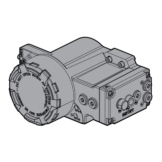
- Page 1 Installation Guide FieldQ DOC.IG.QC41.1 Rev. 4 April 2020 FieldQ Integrated Control Modules QC41 24 V DC QC42 115 V AC QC43 230 V AC (Product Discontinued) FieldQ...
-
Page 2: Before Starting
Installation Guide FieldQ April 2020 DOC.IG.QC41.1 Rev. 4 1 Applicable Control modules: 2 Before starting QC41 - 24 V DC - Weather Proof * Actuator must be isolated both pneumatically Explosion Proof / Flame proof and electrically before any (dis)assembly is QC42 - 115 V AC - Weather Proof begun. - Page 3 Installation Guide FieldQ DOC.IG.QC41.1 Rev. 4 April 2020 2.2 Mechanical alignment and mounting of the control module Alignment-edge The control module is equipped with an alignment- Alignment-edge edge on top of the module. This allows easy alignment and mounting of the control module on to the actuator housing.
-
Page 4: Pneumatic Connections
Installation Guide FieldQ April 2020 DOC.IG.QC41.1 Rev. 4 3 Pneumatic connections IMPORTANT Single acting 1 The actuator/valve combination can move after connecting the air supply. 2 Ensure that the QC4x control modules are mounted properly to the actuator to achieve good functioning and the required ingress Control protection, before connecting the air supply. -
Page 5: Electric Connections
Installation Guide FieldQ DOC.IG.QC41.1 Rev. 4 April 2020 4 Electric Connections Caution! : Risk of electric shock * Installation, adjustment, putting into service, The conventional Control Module contains a pilot use, assembly, disassembly and maintenance valve for controlling the actuator and switches for position feedback. - Page 6 Control Module Type Label = temperature as marked on the control module QC41·MP5MSA1·0040UQP000 (see Table 4.1). 14. Contact your local Emerson representative for information on the dimensions of the flame Pneumatic action proof joints. Switch cartridge 15.Precaution shall be taken to avoid danger of...
- Page 7 Installation Guide FieldQ DOC.IG.QC41.1 Rev. 4 April 2020 Table 4.1 Ambient and maximum surface temperature rating. Configuration Temperature (°C) Switch Pneumatic Max. Power Min. Max. Max. Module type Class cartridge action dissipation ambient ambient Surface -25°C / +60°C / +80°C / QC41 (24 V DC) S,D,F 3.6W...
- Page 8 Installation Guide FieldQ April 2020 DOC.IG.QC41.1 Rev. 4 4.2 Connecting Pilot valve(s) The Control Module can be equipped with one or two pilot valves: * One pilot valve is default and suitable for normal operation of double acting or spring return actuators.
- Page 9 Installation Guide FieldQ DOC.IG.QC41.1 Rev. 4 April 2020 Table 4.4 Maximum currents mechanical switches 4.3 Connecting Mechanical Feedback switches Switch voltage M type switch G type switch 1. Before connecting the switches, check the model code on the Control Module label. 125 V AC 10 A (3 A 0.1 A...
- Page 10 Installation Guide FieldQ April 2020 DOC.IG.QC41.1 Rev. 4 4.4 Connecting 2-Wire proximity switches Switch Switch Switch signal and adjustable operation switch range 1. Before connecting the switches, check the model code on the Control Module label. Close switch QCXX.xxxNxx = 2-Wire NAMUR proximity QCXX.xxxHxx = 2-Wire 230 V AC proximity...
- Page 11 Installation Guide FieldQ DOC.IG.QC41.1 Rev. 4 April 2020 Wiring diagram: 2-Wire NAMUR proximity switches 2-Wire 230 V AC proximity switches Open Close Cable range : 0.33 - 2.5mm or 22 - 12AWG 1 Wiring diagram shown, is applicable for actuators with assembly code “CW”.
- Page 12 Installation Guide FieldQ April 2020 DOC.IG.QC41.1 Rev. 4 4.5 “3-Wire” proximity switches Switch Switch Switch signal and adjustable operation switch range 1. Before connecting the switches, check the model code on the function module label. QCXX.xxxOxx = 3-Wire PNP proximity Close QCXX.xxxCxx = 3-Wire NPN proximity...
-
Page 13: Limit Switch Setting
Installation Guide FieldQ DOC.IG.QC41.1 Rev. 4 April 2020 5 Limit switch setting 5.2.2 Switch point setting and valve rotation direction. The QC41, QC42 and QC43 are equipped with non- 5.1 Factory settings intrusive switch adjustment. The adjustment screws Mechanical stroke : 90°±0.5° (Actuator setting) are accessible behind a small shield in the front of Switch points : ±... - Page 14 Installation Guide FieldQ April 2020 DOC.IG.QC41.1 Rev. 4 5.2.3 Working principles Switch Operating Switch point adjustment Mechanism (see Figure 5.2) The position of the lower pivot block (2) can be The Switch Operating Mechanism is intend to changed by adjustment screw (10) and the position operate the position feedback switches and allows of the upper pivot block (4) can be changed by adjustment of the switch points in the open and...
- Page 15 Installation Guide FieldQ DOC.IG.QC41.1 Rev. 4 April 2020 7. Turn bottom screw (9) clock wise (do not force 5.3 Re-adjustment of switch points the adjustment screw) until the switch trips to the “off state” (no signal). IMPORTANT 8. Turn bottom screw (9) counter clock wise (do not force the adjustment screw) until the switch trips to the “on state”.
-
Page 16: Troubleshooting
Installation Guide FieldQ April 2020 DOC.IG.QC41.1 Rev. 4 6 Trouble shooting 5.4 Check operation 5.4.1 Default (single) pilot valve 6.1 The “Open” and “Closed” position 1 Connect pressure according chapter 3 and a feedback signals are reversed from the control signal to terminals (7) 8 and 9 according actual valve positions. -
Page 17: Maintenance
Installation Guide FieldQ DOC.IG.QC41.1 Rev. 4 April 2020 7 Maintenance Procedure (see Figure 5.3): 1. Remove cover (15) and loosen the screw (11) of the shield (12) and turn the shield down. The FieldQ Control Modules are designed to Closed Position: operate without maintenance. -
Page 18: Related Information
These documents are available, in multiple the speed of the “Opening” and “Closing” stroke languages, for download from simultaneously. www.emerson.com/fieldq 8.2.1 Mounting Speed Control throttle(s): 1 Remove the plug(s) at the side of the module and turn in the throttle (1). -
Page 19: Eu Declaration Of Conformity
Types : QC42...WP... , QC43...WP... Applicable standards : EN 61010-1 : 2010 Note : The above listed ATEX certified products are excluded from the LowVoltage Directive Signed: __________________________ Name: S. Jones Position: Director, Rack and Pinion SBU Emerson Automation Solutions Actuation Technologies Date: 2020-03-09 Place: Houston TX, U.S.A. VCCAQ-15115-EN... - Page 20 VCIOM-15086-EN ©2020 Emerson. All rights reserved. No. 1 Lai Yuan Road EUROPE Wuqing Development Area The Emerson logo is a trademark and service mark of Emerson Holland Fasor 6 Tianjin 301700 Electric Co. FieldQ is a mark of one of the Emerson family of Székesfehérvár 8000...