Table of Contents
Advertisement
Instruction Manual
D101550X012
™
Fisher
8532 High-Performance Butterfly Valve
Contents
. . . . . . . . . . . . . . . . . . . . . . . . . . . . . . . . .
. . . . . . . . . . . . . . . . . . . . . . . . . . . . .
. . . . . . . . . . . . . . . . . . . . . . . . . . . . . . . . .
. . . . . . . . . . . . . . . . . . . . . . . . . . . . . . .
. . . . . . . . . . . . . . . . . . . . . . . . . . . . . . . . . .
. . . . . . . . . . . . . . . . . . . . . . . . . . . .
. . . . . . . . . . . . . . . . . . . . . . . . . . .
. . . . . . . . . . . . . . . . . . . . . . . . . . . . . . . .
. . . . . . . . . . . . . . . . . . . . . . . . .
. . . . . . . . . . . . . . . . . . . . . . . . . . .
. . . . . . . . . . . . . . . . . . . . . . . . . . . . .
. . . . . . . . . . . . . . . . . . . . . . . . . . . .
. . . . . . . . . . . . . . . . . . . . . . . . . . . . . . .
. . . . . . . . . . . . . . . . . . . . . . . . . . . . . . . . . . .
Introduction
Scope of Manual
This instruction manual provides installation, maintenance, and parts information for NPS 14 through 24 Fisher 8532
high-performance butterfly valves.
Do not install, operate, or maintain an 8532 valve without being fully trained and qualified in valve, actuator, and
accessory installation, operation, and maintenance. To avoid personal injury or property damage, it is important to
carefully read, understand, and follow all the contents of this manual, including all safety cautions and warnings. If you
have any questions about these instructions, contact your
proceeding.
Description
The valve is available in either a wafer (flangeless), lugged (single-flange), or double flange body design, with a variety
of seals and internal components. The pressure-assisted seal provides tight shutoff. The spline or keyed drive shaft
combines with a variety of actuators. Maximum inlet pressure/temperature ratings are consistent with CL150 and
CL300.
www.Fisher.com
. . . . . . . . . . . . . . . . . . . . . . . . .
. . . . . . . . . . . . . . . . . . . . .
. . . . . .
. . . . . . . . .
. . . . . . . . . . . . . . . . . . . . . . . .
. . . . . . . . . . . .
. . . . . . . . . . . . .
. . . . . . . . . . . . .
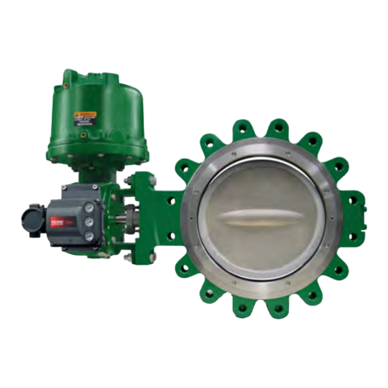
Figure 1. Fisher 8532 Valve with 1061 Actuator and
FIELDVUE™ DVC6200 Digital Valve Controller
1
1
1
2
2
4
5
5
. . . . .
7
7
9
11
12
12
13
14
15
16
17
19
21
22
24
Emerson sales office
or Local Business Partner before
8532 Valve
June 2017
Advertisement
Table of Contents

Related Manuals for Emerson Fisher 8532


Summary of Contents for Emerson Fisher 8532
-
Page 1: Table Of Contents
Introduction Scope of Manual This instruction manual provides installation, maintenance, and parts information for NPS 14 through 24 Fisher 8532 high-performance butterfly valves. Do not install, operate, or maintain an 8532 valve without being fully trained and qualified in valve, actuator, and accessory installation, operation, and maintenance. -
Page 2: Specifications
2. Ratio of maximum flow coefficient to minimum usable flow coefficient may also be called rangeability. Educational Services For information on available courses for Fisher 8532 valves, as well as a variety of other products, contact: Emerson Automation Solutions Educational Services - Registration Phone: 1-641-754-3771 or 1-800-338-8158 E-mail: education@emerson.com... - Page 3 Emerson Sales office or Local Business Partner 1. NACE trim constructions are available; consult your Emerson sales office. 2. Special gasket retainer bolts are required for over 482_C (900_F) 3. Special retaining ring screws for lugged valves over 538_C (1000_F) 4.
-
Page 4: Installation
Emerson sales office or Local Business Partner. 1. Isolate the control valve from the line pressure, release pressure from both sides of the valve body, and drain the process media from both sides of the valve. -
Page 5: Valve Orientation
Instruction Manual 8532 Valve June 2017 D101550X012 Valve Orientation The valve can be installed in any orientation, however it is recommended that the valve drive shaft be horizontal and the actuator vertical as shown in figure 4. Install the valve with the high‐pressure shutoff side in the direction noted by the flow arrow for proper installation, and see figure 4 for more information. - Page 6 Instruction Manual 8532 Valve June 2017 D101550X012 Table 4. Valve Body Data, CL300 FACE‐TO‐FACE DIMENSION SHAFT DIA. AT MINIMUM APPROXIMATE WEIGHT, KILOGRAMS Wafer and VALVE SIZE, .(2) YOKE BEARING Double-Flange Lugged Wafer Lugged Double-Flange 44.45 117.5 304.3 125.2 231.3 44.45 133.4 346.2 189.2...
-
Page 7: Adjusting The Actuator Travel Stops Or Travel
Instruction Manual 8532 Valve June 2017 D101550X012 Figure 2. Available Seal Configurations BACKUP VALVE BODY O-RING SEAL RING T-SLOT RETAINING RING NORMAL FLOW DIRECTION VALVE DISK PTFE OR UHMWPE SOFT SEAL WITH BACKUP O-RING GRAPHITE GRAPHITE VALVE BODY VALVE BODY GASKET GASKET BACKUP... - Page 8 Instruction Manual 8532 Valve June 2017 D101550X012 Figure 3. Stud Bolts for Installation (also see table 5) WAFER BODY OR LUGGED BODY LUGGED BODY AND TAPPED HOLES IN WAFER WITH DRILLED THROUGH HOLES BODY (NEAR SHAFT BORE) (1)(2) Table 5. Hex Head Screw, Stud Bolt and Cap Screw Data Wafer Bodies or Lugged Bodies with Drilled Through Holes Number of Number of...
-
Page 9: Packing Adjustment And Shaft Bonding
Instruction Manual 8532 Valve June 2017 D101550X012 Figure 4. Installation of Wafer‐Style Valves A5557 1. See figure 4 for recommended valve orientation. D For Wafer‐Style Valves: Install the lower flange bolts first to form a cradle for the valve (see figure 5). See table 5 for flange bolt specifications. - Page 10 Instruction Manual 8532 Valve June 2017 D101550X012 Figure 5. Proper Installation Steps VALVE IN CLOSED POSITION DURING INSTALLATION (OR REMOVAL) TO PREVENT DAMAGE TO DISK SEALING AREA. SHAFT HORIZONTAL FLANGE GASKETS: PIPE FLANGES: BE SURE THESE ARE OPENED ENOUGH TO ALLOW THE CENTERED ALONG WITH VALVE AND GASKETS TO SLIP EASILY INTO PLACE VALVE...
-
Page 11: Maintenance
Instruction Manual 8532 Valve June 2017 D101550X012 Figure 6. Optional Shaft‐to‐Valve Body Bonding Strap Assembly ACTUATOR VALVE BODY 37A6528‐A A3143‐2 VIEW A‐A Note Standard PTFE packing is composed of a partially conductive carbon‐filled PTFE female adaptor with PTFE V‐ring packing. Standard graphite packing is composed of all conductive graphite ribbon packing. -
Page 12: Removing And Replacing The Actuator
Instruction Manual 8532 Valve June 2017 D101550X012 D Vent the power actuator loading pressure. D Use lockout procedures to be sure that the above measures stay in effect while you work on the equipment. D The valve packing box may contain process fluids that are pressurized, even when the valve has been removed from the pipeline. -
Page 13: Removing The Valve
Instruction Manual 8532 Valve June 2017 D101550X012 The packing is now accessible. 3. Use a packing extractor to remove packing. Insert the corkscrew‐like end of the tool into the first piece of packing and pull firmly to remove the packing. Repeat this process until all packing parts have been removed. Figure 7. -
Page 14: Seal Maintenance
Instruction Manual 8532 Valve June 2017 D101550X012 3. Loosen the flange bolting that holds the valve. Make sure the valve cannot slip or twist while loosening and removing the bolting. 4. Before removing the valve from the pipeline, make sure the valve disk is closed. Removing the valve with the disk open could cause damage to the disk, piping, or pipe flanges. -
Page 15: Ptfe Seals
1000 Note: These values are based upon standard materials, S66286/N07718 screws and ASTM A193GRB6 bolts. For other special fastener materials, please contact your Emerson sales office Local Business Partner. PTFE Seals 1. Locate the replacement seal ring (key 5) and note the shape of the ring. The ring is wider across one edge diameter and narrower across the other edge diameter. -
Page 16: Novex, Phoenix Iii And/Or Phoenix Iii Fire-Tested Seals
Instruction Manual 8532 Valve June 2017 D101550X012 3. Carefully tuck the O‐ring downward into the body T‐slot until the seal ring is completely entrapped in the body T‐slot, and it completely covers the backup O‐ring. 4. Re‐install the retaining ring and the socket head cap screws. Tighten the cap screws just enough to eliminate any movement of the retaining ring. -
Page 17: Anti-Blowout Design, Packing, Valve Shaft, Disk, And Bearing Maintenance
Instruction Manual 8532 Valve June 2017 D101550X012 7. Manually rotate the upper shaft (key 3) to turn the disk clockwise to meet the seal. 8. Tap the disk with a rubber mallet to drive it against the internal travel stop. When the disk makes contact with the stop, manually rotate the disk counterclockwise back out of the seal to a 90‐degree open position. - Page 18 Instruction Manual 8532 Valve June 2017 D101550X012 CAUTION Never use a wrench, pliers, or similar tool to turn the upper shaft. A damaged shaft can cut the packing and allow leakage. Note It is not necessary to remove the retaining ring and valve seal when removing the shaft(s) and disk. WARNING Avoid personal injury or property damage caused by the impact of a falling or tipping of a large valve.
-
Page 19: Installing The Two-Piece Shaft
Instruction Manual 8532 Valve June 2017 D101550X012 8. Before removing the upper shaft (key 3), be sure the valve disk is properly supported. Pull out the upper shaft (key 3) by hand‐pulling or by using a shaft extractor screwed into the end of the shaft. CAUTION To avoid damage to the disk, seal, and T‐slot area, do not force the disk past the seal or T‐slot area. - Page 20 Instruction Manual 8532 Valve June 2017 D101550X012 2. Inspect all parts removed from the valve for wear or damage. Replace any worn or damaged parts. Clean the valve body and all parts to be installed with an appropriate solvent or degreaser. Note When installing the bearings, apply lubricant to the outside diameter of the bearing for ease of installation.
-
Page 21: Gasket Retainer
Instruction Manual 8532 Valve June 2017 D101550X012 CAUTION To avoid damage to the tangential pins, disk pins, valve disk, or shaft(s) resulting from the application of excessive force, use appropriate care when driving the pins into the disk hub and shaft(s). Use the right tool. Do not use excessive force. 12. -
Page 22: Parts Ordering
Local Business Partner about an 8532 valve, identify the valve as a Fisher 8532 and provide the valve serial number. For valve/actuator combinations assembled at the factory, the valve serial number may be stamped on the nameplate attached to the actuator. - Page 23 44.5 (1‐3/4) RRTYXRT0632 RRTYX000212 CL300 63.5 (2‐1/2) RRTYXRT0642 RRTYX000222 CL150 50.8 (2) RRTYXRT0652 RRTYX000182 CL150 63.5 (2‐1/2) RRTYXRT0662 RRTYX000222 1. Shaft diameter: Diameter through the packing box. 2. For larger shaft sizes, consult your Emerson sales office or Local Business Partner.
-
Page 24: Parts List
21* Gasket 22 Lockwasher (4 req'd) Note 23 Cap Screw (4 req'd) Contact your Emerson sales office or Local Business Partner for Part 24* Thrust Bearing Ordering information. 26* Retaining Ring Gasket 27 Cap Screw - Actuator (4 req'd) (not shown) 28... - Page 25 Instruction Manual 8532 Valve June 2017 D101550X012 Figure 9. Fisher 8532, NPS 14-24, CL150-300 PARTS NOT SHOWN: KEY 26, 29, 32, 33, 38, 111, 112, 113 USE ONLY WITH SOFT SEAL AND PHOENIX III SEAL. GE58725-A...
- Page 26 Instruction Manual 8532 Valve June 2017 D101550X012 Figure 10. Fisher 8532, NPS 14-24, CL150-300, Double Flange Valve Body PARTS NOT SHOWN: KEY 26, 29, 32, 33, 38, 111, 112, 113 USE ONLY WITH SOFT SEAL AND PHOENIX III SEAL. GE58760-A...
- Page 27 Instruction Manual 8532 Valve June 2017 D101550X012 Figure 11. ENVIRO‐SEAL Packing Systems 14B0095‐A 34B7524‐B STACKING ORDER OF PTFE PACKING SYSTEM PTFE PACKING RINGS 14B0086‐A STACKING ORDER OF GRAPHITE PACKING RINGS 34B7524‐B GRAPHITE PACKING SYSTEM NOTES: VALVES WITH SHAFTS LARGER THAN 38.1 mm (1-1/2 INCH) USE GRAPHITE RINGS...
- Page 28 Fisher and ENVIRO-SEAL are marks owned by one of the companies in the Emerson Automation Solutions business unit of Emerson Electric Co. Emerson Automation Solutions, Emerson, and the Emerson logo are trademarks and service marks of Emerson Electric Co. All other marks are the property of their respective owners.