Table of Contents
Advertisement
Quick Links
All manuals and user guides at all-guides.com
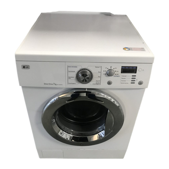
WASHING MACHINE
SERVICE MANUAL
CAUTION
READ THIS MANUAL CAREFULLY TO DIAGNOSE TROUBLE
CORRECTLY BEFORE OFFERING SERVICE.
MODEL : WD(M)-16350(5)FD / WD-16320(5)FD
WD(M)-16351(6)FD / WD-14320(5)FD
WD(M)-14350(5)FD / WD-12320(5)FD
WD(M)-14351(6)FD
WD(M)-12350(5)FD
WD(M)-12351(6)FD
website : http://www.LGEservice.com
e-mail : http://LGEservice.com/techsup.html
100
Advertisement
Table of Contents
Troubleshooting

Related Manuals for LG WDM-16350FD


Summary of Contents for LG WDM-16350FD
- Page 1 All manuals and user guides at all-guides.com website : http://www.LGEservice.com e-mail : http://LGEservice.com/techsup.html WASHING MACHINE SERVICE MANUAL CAUTION READ THIS MANUAL CAREFULLY TO DIAGNOSE TROUBLE CORRECTLY BEFORE OFFERING SERVICE. MODEL : WD(M)-16350(5)FD / WD-16320(5)FD WD(M)-16351(6)FD / WD-14320(5)FD WD(M)-14350(5)FD / WD-12320(5)FD WD(M)-14351(6)FD WD(M)-12350(5)FD WD(M)-12351(6)FD...
- Page 2 All manuals and user guides at all-guides.com APR. 2005 PRINTED IN KOREA P/No.:3828ER3035U...
-
Page 3: Table Of Contents
All manuals and user guides at all-guides.com CONTENTS 1. SPECIFICATION..........................3 2. FEATURES & TECHNICAL EXPLANATION .................4 3. PARTS IDENTIFICATION ......................6 4. INSTALLATION ..........................7 5. OPERATION ..........................10 6. WIRING DIAGRAM / PROGRAM CHART ...................12 7. TROUBLESHOOTING.........................13 7-1.BEFORE PERFORMING SERVICE ..................13 7-2.QC TEST MODE........................13 7-3.HOW TO KNOW THE WATER LEVEL FREQUENCY............13 7-4.ERROR DISPLAY ........................14... -
Page 4: Specification
All manuals and user guides at all-guides.com 1. SPECIFICATION WD(M)-16350(5)FD WD(M)-14350(5)FD WD(M)-12350(5)FD WD(M)-16351(6)FD WD(M)-14351(6)FD WD(M)-12351(6)FD ITEM WD-16320(5)FD WD-14320(5)FD WD-12320(5)FD POWER SUPPLY 220-240V~, 50Hz PRODUCT WEIGHT 65kg WASHING 230W ELECTRICITY SPIN 600W CONSUMPTION DRAIN MOTOR WASH HEATER 2000W WASH 45rpm 1600 rpm : 400/800/1000/1200/1600 rpm REVOLUTION SPEED SPIN... -
Page 5: Features & Technical Explanation
All manuals and user guides at all-guides.com 2. FEATURES & TECHNICAL EXPLANATION 2-1.FEATURES Jumbo drum ’s jumbo drum can wash about 40% more load than conventional washing machine. A bigger drum improves the wash performance. More economical by Intelligent Wash System Intelligent Wash System detects the amount of load and water temperature, and then determines the optimum water level and washing time to minimize energy and water consumption. - Page 6 All manuals and user guides at all-guides.com 2-2.DETERMINE WASHING TIME BY FUZZY LOGIC To get the best washing performance optimal time is determined by sensing of water temperature, selected washing temperature and laundry amount. water temperature washing time the best selected FUZZY washing...
-
Page 7: Parts Identification
All manuals and user guides at all-guides.com 3. PARTS IDENTIFICATION ACCESSORIES Inlet hose(1EA) Option : Hot/Cold(2EA) Spanner... -
Page 8: Installation
All manuals and user guides at all-guides.com 4. INSTALLATION Before servicing ask the customer what the trouble is. Check the adjustment (power supply is 220-240V~, remove the transit bolts..) Check the troubles referring to the troubleshooting. Decide service steps referring to disassembly instructions. Then, service and repair. - Page 9 All manuals and user guides at all-guides.com HOW TO CONNECT INLET HOSE Check that the rubber washer is inside of the valve connector. Connect the inlet hose firmly to prevent leak. CONNECT DRAIN HOSE Make sure that the hose is not twisted. Avoid submerging the end of the hose.
- Page 10 All manuals and user guides at all-guides.com TEST OPERATION Preparation Press the power button. Press the Start/Pause for washing. button. Connect the power plug to the outlet. In case of coloureds program. Connect the inlet hose. Check the water heating. Check automatic reverse Check the water supply.
-
Page 11: Operation
All manuals and user guides at all-guides.com 5. OPERATION Wash program selector LED display 8 program can be set depending on the type of the laundry. Display the estimated remaining time (Hour : Minute) to finish. If the power button is pressed, Cotton program is automatically In case of abnormal operation, error set. - Page 12 All manuals and user guides at all-guides.com Child - Lock Time Delay Child Lock system can be set and Press the button when delayed washing is canceled by pressing and holding needed. both [Rinse + ] and [Pre Wash] buttons When the button is pressed, is displayed, simultaneously more than 2 seconds.
-
Page 13: Wiring Diagram / Program Chart
All manuals and user guides at all-guides.com 6. WIRING DIAGRAM PROGRAM CHART (Hour:Minute) (With Intensive) Time 120 MIN 60 60 240 120 360 60 240 120 360 60 240 120 360 60 240 120 360 60 480 120 20 (SEC) Cotton About 1:45(40) (BIG) -
Page 14: Troubleshooting
All manuals and user guides at all-guides.com 7. TROUBLESHOOTING 7-1.BEFORE PERFORMING SERVICE Be careful of electric shock or disconnecting the parts while troubleshooting. Voltage of each terminal in 220-240V~ and DC while applying an electric current. 7-2.QC TEST MODE. Press Intensive and Rinse + button simultaneously. Power supply on with pressing upper two buttons.Then buzzer sound twice. -
Page 15: 7-4.Error Display
All manuals and user guides at all-guides.com 7-4.ERROR DISPLAY. If you press the Start/Pause button when an error in displayed, any error except will disappear and the machine will change into pause status. In case of if the error is not resolved within 15 sec. and in case of other errors, if the error is not resolved within 4 min., power will be turned off automatically and the error only will be blinked. - Page 16 All manuals and user guides at all-guides.com ERROR SYMPTOM CAUSE • MAIN PWB ASSEMBLY is out of order Replace the MAIN PWB ASSEMBLY CURRENT • Winding in the STATOR ASSEMBLY is short-circuited. ERROR Replace the STATOR ASSEMBLY • The connector (3-pin, male, white) in the LEAD WIRE ASSEMBLY is not connected to the connector (3-pin, female, white) of LOCK STATOR ASSEMBLY.
-
Page 17: Error Diagnosis And Check List
All manuals and user guides at all-guides.com 8. ERROR DIAGNOSIS AND CHECK LIST 8-1.DIAGNOSIS AND ANSWER FOR ABNORMAL OPERATION SYMPTOM GUIDE FOR SERVICE CALL NO POWER Is the power plug connected firmly to 220-240V~ outlet? Power failure? or Breaker opened? Is the outlet controlled by a switch Visit to check WATER INLET TROUBLE... - Page 18 All manuals and user guides at all-guides.com SYMPTOM GUIDE FOR SERVICE CALL DOOR OPEN ERROR Did you press the Start/Pause button when Close the door the door is open? Visit to check Check if the door switch is O.K displayed? DRAIN TROUBLE Is the debris filter clogged with foreign Clean up...
- Page 19 All manuals and user guides at all-guides.com SYMPTOM GUIDE FOR SERVICE CALL Suds overflow from the Is low-sudsing detergent for the drum appliance. washing machine used? (In this condition, wash and spin do not operate LOW-SUDSING normally) Is the proper amount of detergent used DETERGENT as recommended? Recommend to reduce the amount...
-
Page 20: Fault Diagnosis And Troubleshooting
All manuals and user guides at all-guides.com 8-2.FAULT DIAGNOSIS AND TROUBLESHOOTING CAUTION 1. Be careful of electric shock or disconnecting the parts while troubleshooting. 2. First of all, check the connection of each part terminal with wiring diagram. 3. If you replace the MAIN PWB ASSEMBLY, put in the connectors correctly. NO POWER When measuring the voltage of the outlet, Check the fuse... - Page 21 All manuals and user guides at all-guides.com NO WATER SUPPLY Is water supply shut-off? Is the tap opened? Open the tap. Check the AIR CHAMBER When you press both Time Delay button and Rinse + button simultaneously, is the water level and the tube clogged frequency below 240? with impurity.
- Page 22 All manuals and user guides at all-guides.com SOFTENER DOES NOT FLOW IN Refer to Option (Hot) Is water supplied? NO WATER SUPPLY Check the wiring on the Are receptacles correctly connected to the terminals dispenser. of the INLET VALVE ASSEMBLY? Wiring diagram Is softener put in the correct compartment of the Put it in the correct...
- Page 23 All manuals and user guides at all-guides.com HEATING WITHOUT WATER When pressing Time Delay and Rinse + at the same time after draining, is the water level frequency 255 Replace the or more? When pressing Time Delay, Rinse + S.PRESSURE SWITCH buttons at the same time while wash, is the water ASSEMBLY level frequency between 230 - 243 ?
- Page 24 All manuals and user guides at all-guides.com WASH HEATER TROUBLE MAIN PWB ASSEMBLY When checking the voltage between Replace the MAIN PWB connectors ( ) during ASSEMBLY whites washing, Is the voltage 220 - 240V 220-240V After power off,is the resistance of wire YELLOW (RED-YELLOW) connectors between Normal...
- Page 25 All manuals and user guides at all-guides.com SPIN TROUBLE Check the sensor Check on the spinning, is the frequency of the (Pressure) or hose water level 248 or more? The frequency can be (Sensor). If the problem checked by pressing the Time Delay and Rinse + is on the sensor or the buttons at the same time on the program.
-
Page 26: Disassembly Instructions
All manuals and user guides at all-guides.com 9. DISASSEMBLY INSTRUCTIONS Be sure to unplug the machine out of the outlet before disassembling and repairing the parts. CONTROL PANEL ASSEMBLY Unscrew 2 screws on the back of the top plate. Top Plate Assembly Pull the top plate backward and upward as shown. - Page 27 All manuals and user guides at all-guides.com DISPENSER ASSEMBLY Disassemble the TOP PLATE ASSEMBLY. Pull out the drawer slightly upward. Unscrew 2 screws. PUSH DRAWER Disassemble hose clamps and hoses. Option DISPENSER ASSEMBLY Disassemble the ventilation bellows and the water inlet bellows from the tub.
- Page 28 All manuals and user guides at all-guides.com INLET VALVE ASSEMBLY Disconnect the wiring connector. 3 Option Unscrew 2 screws from the back. When reconnecting the connector Cold only model VALVE#1 (MAIN) Whited/Black-Black VALVE#2 (PRE) Gray/ White - Black Cold and Hot model VALVE #1 (MAIN) Whited/Black-Black VALVE #2 (PRE)
- Page 29 All manuals and user guides at all-guides.com DOOR ASSEMBLY Open the door completely. Remove the two screws from the hinge. When removing the DOOR ASSEMBLY, it is necessary to hold the BRACKET that is inner of the CABINET COVER. GASKET Take apart the CLAMP ASSEMBLY (cabinet).
- Page 30 All manuals and user guides at all-guides.com ROTOR ASSEMBLY, STATOR ASSEMBLY, FRICTION DAMPER ASSEMBLY Remove the BACK COVER. Unscrew the bolt to pull out the ROTOR ASSEMBLY. Rotor Bolt (ROTOR ASSEMBLY) Disconnect the wiring connector. Unscrew 6 bolts from the STATOR. Remove the STATOR.
- Page 31 All manuals and user guides at all-guides.com DRAIN PUMP ASSEMBLY Remove PUMP HOSE. PUMP HOSE Remove BELLOWS.. Disconnect the wiring. Unscrew 2 screws Screw Remove the DRAIN PUMP ASSEMBLY. (Remaining Hose) BELLOWS HEATER ASSEMBLY Loosen the M6 heater nuts to pull out the HEATER ASSEMBLY.
- Page 32 All manuals and user guides at all-guides.com SWITCH ASSEMBLY, DOOR LOCK Take apart the CLAMP ASSEMBLY (cabinet) and release the GASKET. Unscrew 2 screws holding the DOOR SWITCH ASSEMBLY. Disconnect the door lock from the wiring connector. WHEN FOREIGN MATERIAL IS STUCK BETWEEN DRUM AND TUB Remove the HEATER ASSEMBLY.
-
Page 33: Exploded View And Parts List
All manuals and user guides at all-guides.com 10. EXPLODED VIEW AND PART LIST 10-1.THE PART LIST OF CABINET ASSEMBLY A140 A110 A154 A153 A102 A152 A150 A104 A151 A103 A101 A141 A131 A100 A430 A130 A440 A134 A485 A410 A133 A240 A303 A310... -
Page 34: The Exploded View Of Control Panel And Dispenser Assembly
All manuals and user guides at all-guides.com 10-2 THE EXPLODED VIEW OF CONTROL PANEL & DISPENSER ASSEMBLY F170 F322 F321 F462 F160 F300 F320 F465 F466 F432 F225 F436 F430 F220 F431 F435 F441 F120 F440 F463 F110 F310 F215 F464 A450 F216... -
Page 35: The Exploded View Of Drum And Tub Assembly
All manuals and user guides at all-guides.com 10-3 THE EXPLODED VIEW OF DRUM & TUB ASSEMBLY K350 K360 K143 K123 F140 K121 K122 K411 K125 K351 K420 K320 K110 K111 K141 K310 K140 K311 K105 K115 K410 K610 K510 K611 K130 K530 K131...