Advertisement
Quick Links
GPS Antenna
With built-in Heading
Sensor
Installation Guide
ENGLISH
www.lowrance.com | www.simrad-yachting.com | www.bandg.com
*988-10439-003*
Supplied parts
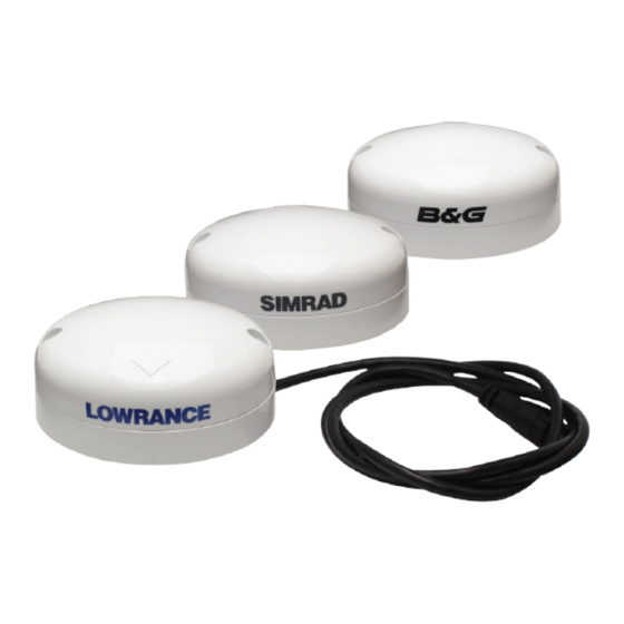
Lowrance® Point-1
Simrad® GS25
B&G® ZG100
X 2
X 2
X 2
X 2
X 2
Attached NMEA 2000®
NMEA 2000®
NMEA 2000® Drop
Drop cable 1.2 m (4 ft)
Drop cable 4.5 m
cable 1.8 m (6 ft)
+ NMEA 2000® Drop
(15 ft)
cable 4.5 m (15 ft)
Antenna mounting location
Magnetic Field
X
RADAR
X
2 m (6 ft) Min
0.5 m (20") Min
0.5 m (20") Min
Radio Transmitter
X
Electromagnetic Interference
Surface mount the antenna
1
2
19 mm
3 mm
X 2
3
5
4
Pole mount (external cable)
1
2
3
X
X
5
4
Surface mount: Surface cable run
2
60 mm
5
Pole mount (Internal cable)
1
2
5
6
Surface cable run
3
4
Advertisement

Summary of Contents for Lowrance Point-1
- Page 1 Drop cable 1.2 m (4 ft) Drop cable 4.5 m cable 1.8 m (6 ft) + NMEA 2000® Drop (15 ft) cable 4.5 m (15 ft) www.lowrance.com | www.simrad-yachting.com | www.bandg.com Pole mount (external cable) Pole mount (Internal cable) Antenna mounting location Magnetic Field RADAR 2 m (6 ft) Min 0.5 m (20”) Min...
- Page 2 Disconnect then reconnect the sensors NMEA 2000® cable. Cold start 50 sec as a GPS antenna. In this case, the Point-1 unit that is used as the Make two consecutive turns of 360 degrees. The completion Start-up time 3 sec heading sensor must be set to instance ‘1’...


