Table of Contents
Advertisement
Quick Links
Advertisement
Table of Contents
Troubleshooting

Related Manuals for Siemens 9410 Series


Summary of Contents for Siemens 9410 Series
- Page 1 9410 series User manual 7EN05-0336-03 11/2017 www.usa.siemens.com/pds...
- Page 2 Please note Electrical equipment should be installed, operated, serviced and maintained only by qualified personnel. No responsibility is assumed by Siemens Industry for any consequences arising out of the use of this material. A qualified person is one who has...
- Page 3 This digital apparatus complies with CAN ICES-3 (B) /NMB-3(B). About this manual This manual discusses features of the 9410 series power meter and provides installation and configuration instructions. Throughout the manual, the term “meter” refers to all models of the 9410. All differences between the models, such as a feature specific to one model, are indicated with the appropriate model number or description.
- Page 4 9410 series Related documents Document Number 9410DC / 9410D24VDC installation sheet NVE23944 9410TC and 9410T24VDC installation sheet NVE23945 ION Reference 70005-0290 — ION device template reference 7EN05-0336-03...
-
Page 5: Table Of Contents
9410 series Table of Contents Safety precautions ..................11 Meter overview ....................12 9410 overview ....................12 Your meter in an energy management system ..........12 Measured parameters ..................13 Localization ....................15 Data display and analysis tools ...............15 Supported protocols ..................16 ION Setup device configuration tool..............16 Meter types....................16... - Page 6 9410 series Security features on your device..............42 Network port control..................42 Enable/disable communication ports............42 Revenue and billing security features ............43 Event logging ...................43 Syslog .....................43 Advanced security through the meter’s display ...........43 NERC CIP .....................43 Security recommendations and best practices..........44 Password best practices ................44 Standard and advanced security features ............45...
- Page 7 9410 series Accessing the meter’s webpages for data viewing and meter configuration....................109 Viewing files using your meter’s webpages ............ 110 Creating custom webpages for your meter ............. 110 Sample data viewing webpage ..............111 Logging ......................119 Logging overview ..................119 Data logging overview ..................
- Page 8 9410 series Alerting......................159 Setpoint learning overview ................160 Learning installation mode and learning duration ..........160 Resets ......................164 Meter resets ....................164 Option module reset ..................164 Available resets ................... 164 Measurements ....................168 Power and power factor ................168 Power demand.....................
- Page 9 9410 series Revenue locking your meter................192 PT/CT correction ..................192 Time of use....................193 Specifications overview ................194 Mechanical characteristics ................194 Electrical characteristics ................194 Environmental characteristics ............... 196 LEDs......................197 EMC (electromagnetic compatibility).............. 197 Safety ......................198 Ethernet communications ................
-
Page 11: Safety Precautions
Safety precautions 9410 series Safety precautions Installation, wiring, testing and service must be performed in accordance with all local and national electrical codes. DANGER HAZARD OF ELECTRIC SHOCK, EXPLOSION, OR ARC FLASH Failure to follow these instructions will result in death or serious injury. -
Page 12: Meter Overview
Meter overview Meter overview 9410 overview The 9410 series power and energy meters help meet the needs of your energy monitoring and cost management applications. All 9410 meters comply with international metering accuracy standards. You can customize your meter by loading specialized frameworks, and adding option modules and incorporating mounting accessories into the physical installation. -
Page 13: Measured Parameters
Meter overview 9410 series Inputs / outputs Alarming and alerting Highly accurate metering Data and event logging Powerful customization Measure Tre nding a nd forecasting Simple configuration Power quality monitoring Understa Easy access Ene rgy ma na ge me nt... - Page 14 9410 series Meter overview Demand Your meter supports several demand calculation methods, including block, rolling block, synchronized and predicted demand. It can measure demand on any instantaneous value and record peak (maximum) and minimum demand with time and date information.
-
Page 15: Localization
Meter overview 9410 series • COMTRADE: this allows the meter to save waveform data in COMmon format for TRAnsient Data Exchange (COMTRADE) on its internal FTP server. Your meter includes the following power quality compliance: • EN50160: Your meter measures and presents statistics for determining EN50160 compliance. -
Page 16: Supported Protocols
You can download ION Setup from www.usa.siemens.com/pds. See the online ION Setup help, available from www.usa.siemens.com/pds, for instructions on connecting to your meter. Meter types The 9410 series is available in two physical form factors, and has several accessories. Model Commercial reference Description... -
Page 17: Mounting Adaptors
Meter overview 9410 series Model Commercial reference Description 9410RVDC US2:9410R24VDC Same as the 9410TC, except with low-voltage DC control power 948DISP96 US2:948DISP96 Remote display (for DIN meter only) 948M2DO6DI US2:948M2DO6DI Digital I/O option module (2 outputs, 6 inputs) 948M2AO4AI US2:948M2AO4AI... -
Page 18: Basic Setup
9410 series Basic setup Basic setup Default values for commissioning Use these default settings for the first time you connect to and configure your meter. Parameter Default value Display password (also for logging onto meter webpages) Username (for logging onto meter webpages) -
Page 19: Minimum Configuration Requirements For Basic Metering
Basic setup 9410 series Voltage polarity setup Parameter Values Description Va Polarity Normal, Inverted The polarity of the potential transformer on Va Vb Polarity Normal, Inverted The polarity of the potential transformer on Vb Vc Polarity Normal, Inverted The polarity of the potential transformer on Vc... -
Page 20: Hardware Reference
See your product’s catalog pages at www.usa.siemens.com/pds for information about your device, its options and accessories. You can download updated documentation from www.usa.siemens.com/pds or contact your local Siemens Industry representative for the latest information about your product. Meter base Your meter base has two form factors, panel mount and DIN mount. -
Page 21: Remote Meter Display (Rmd)
Remote display connector Mounting hardware and accessories not shown. See the 9410 catalog pages, available from www.usa.siemens.com/pds, or consult your local Siemens Industry representative for information about your device, its options and accessories. Remote meter display (RMD) The remote meter display can be used with DIN meters. -
Page 22: Mounting Adaptors
9410 series Hardware reference Mounting adaptors There are different mounting adaptor accessories that can help when installing your meter in existing panels and cutouts where the default mounting hardware is not appropriate. Mounting adaptor kits are ordered separately from the meter. -
Page 23: Energy Pulsing Led Behavior
Hardware reference 9410 series Status Energy pulsing Infrared energy pulsing Revenue lock status Remote display connection link Remote display connection activity Related Topics • Alarm and status LED indicators Energy pulsing LED behavior The visible and infrared LEDs are configured by default to pulse based on energy measured by the meter. -
Page 24: Panel-Mount Meter And Remote Display Mounting And Wiring Recommendations
9410 series Hardware reference Panel-mount meter and remote display mounting and wiring recommendations There are supplemental mounting and wiring recommendations that apply to panel- mount meters and remote displays. • The meter is intended to be mounted inside a ¼-DIN panel cutout. -
Page 25: Ethernet Communications Connections
Hardware reference 9410 series NOTE: If some devices in your RS-485 network do not have the C terminal, use the bare wire in the RS-485 cable to connect the C terminal from the meter to the shield terminal on the devices that do not have the C terminal. - Page 26 9410 series Hardware reference of option modules. Refer to Maximum operating temperature, page 197 for more information. For a panel mount meter, one limitation on the number of modules that can be attached is the physical strength of the meter mounting hardware. If your meter is mounted in an area subject to vibration or other physical stresses, your meter’s ability...
-
Page 27: Meter Display
Meter display 9410 series Meter display Display overview The display allows you to view meter data and perform basic configuration. Your meter can have either an integrated or an optional remote display. The integrated and remote display screens have the same meter data and setup screens. Only meters without an integrated display can use the remote display. - Page 28 9410 series Meter display Related Topics • Revenue locking Alarm icon The alarm icon indicates the highest level and state of alarms detected by your meter. For example, if the meter detects a low priority and a high priority active alarm, the alarm icon indicates a high priority active alarm.
- Page 29 Meter display 9410 series Related Topics • LED locations Navigation symbols Navigation symbols are displayed on the bottom of the screen above their corresponding navigation button. NOTE: If the symbol is gray, that navigation function is not available. Symbol Description More Pressing this button displays additional screens.
-
Page 30: Display Menu
9410 series Meter display Overrange indication If any value measured by the meter is too large to fit on the meter’s display, the meter initially reduces the size of the text to try and make the value fit. If the value is still too large to be displayed, the meter truncates the value starting with the least significant digit, and encloses the truncated value in a red box. - Page 31 Meter display 9410 series Menu Menu screens Content Summary Summary Power system summary Alarms Active alarms, historical Active and historical alarms can be viewed and alarms acknowledged. Basic readings Voltage, current, • Power system voltage (line-to-line or line-to- frequency neutral), current and frequency values.
- Page 32 9410 series Meter display 2. Press to highlight a specific alarm, in this case an unbalanced currents alarm. Press to display detailed information about the highlighted alarm, and press to return to the Active Alarms screen. Press both simultaneously to acknowledge all active alarms.
- Page 33 Meter display 9410 series 2. Press to view a graphical display of historic voltage values, then press return to the numeric display. Press to show a list of additional screens. 3. Press to highlight an additional screen, in this case, Volts II Average.
-
Page 34: Setup Menu
9410 series Meter display 5. Press to view Volts L-N, which also has additional screens and the ability to view the information in a graphical format. 6. Press again to view Volts Unbalanced. This is the last voltage screen, so is grayed out and unavailable. - Page 35 Meter display 9410 series Sample Volts Mode Meter Setup Sample T/CT S e tup Sample Volta ge P ola rity S e tup Curre nt P ola rity S e tup Sample Sample Nomina l Va lue s Sample Ethe rne t P ort Ena ble S e tup...
- Page 36 9410 series Meter display 1. Press to display the menu. Press until Setup Menu is highlighted. Press to display the Setup Menu. The Setup Menu lists the setup selections on your meter. 2. Press to highlight the different setup menu selections. Highlight Meter Setup and press to select the meter setup screens.
-
Page 37: Using The Onscreen Keyboard
Meter display 9410 series 6. Press to confirm, and the new setting is applied to your meter. Press cancel and maintain your meter’s original setting. 7. In the Volts Mode screen, press to go to the PT/CT Setup screen. 8. In the PT/CT Setup screen, press to highlight the potential transformer (PT) or current transformer (CT) value for editing. - Page 38 9410 series Meter display 1. Use the left, right and up buttons to move the highlighted key. Pressing up from the top row returns the highlighted key to the bottom row and pressing left or right at the end of one side causes the highlighted key to wrap around to the opposite side.
-
Page 39: Remote Display Troubleshooting Icons
Meter display 9410 series Numeric format setup Parameter Values Description Digit Grouping 1000.0, 1,000.0, 1 000,0 Specifies how digits are grouped for display Volts Resolution 1., 1.X, 1.XX, 1.XXX, 1.XXXX Specifies the number of decimal places displayed for voltages Current 1., 1.X, 1.XX,1.XXX, 1.XXXX... -
Page 40: Creating Custom Displays Using Ion Setup
9410 series Meter display Icon Description Your remote display cannot communicate to your meter. Check the connection between your meter and the display. Check the meter’s status LED to confirm that the meter is operating normally. Your remote display needs updated firmware for compatibility with your meter. - Page 41 Meter display 9410 series 8. Select your digit display properties. • Resolution: Specifies the number of decimal places displayed. • Last Digit: Enter the title to be shown at the top of your custom display. 9. Click Send to save the changes in the meter.
-
Page 42: Security
Security Security Security overview Your Siemens Industry product is equipped with security-enabling features. These features arrive in a default state and can be configured for your installation needs. Please note that disabling or modifying settings within the scope of these individual features can impact the overall security robustness of the device and ultimately the security posture of your network in either positive or negative ways. -
Page 43: Revenue And Billing Security Features
Security 9410 series Related Topics • Disable the COM port using the meter webpages • Disabling the COM port using the meter display • Disabling the COM port using ION Setup Revenue and billing security features Selected meter models support additional hardware and firmware locking to prevent unauthorized access to revenue-related parameters and settings. -
Page 44: Security Recommendations And Best Practices
9410 series Security This meter has incorporated security features that allow it to be part of NERC CIP compliant facility. For example, the security features of this meter include user accounts with configurable passwords and permissions; network port control configuration; security access and event log replication to an external server; and digitally signed firmware. -
Page 45: Standard And Advanced Security Features
Security 9410 series Standard and advanced security features Security settings allow you to configure security features on your meter. Parameter Standard/ Details advanced Meter password Standard/ The meter’s password is used to confirm user access when advanced configuring the meter through the display or over communications. -
Page 46: Communications Protocol Lockout Overview
9410 series Security • Set user passwords. Communications protocol lockout overview The communications protocol lockout security feature allows you to set the number of invalid login attempts that each user can make using a particular protocol and communications method before being locked out (a user is defined as a user login and password combination). -
Page 47: Password Setup
Security 9410 series Related Topics • Configuring standard security using ION Setup Password setup It is strongly recommended that you change your meter’s password from the default value of 0 (zero). Your meter’s username and password cannot be retrieved if lost. If you lose your meter’s user access information, you will not be able to change any settings or access... -
Page 48: Configuring Standard Security Using Ion Setup
9410 series Security Configuring standard security using ION Setup You can fully configure standard and advanced security on your meter using ION Setup. In order to change security settings, you must be logged into ION Setup with an appropriate ION Setup user level. You must also have the appropriate meter-level security access to configure meter security. -
Page 49: Configuring Users And Passwords Using Ion Setup (Advanced Security Only)
Security 9410 series 10. If you have selected standard security, click Finish. You are prompted to save your security configuration to a file which can be loaded onto other meters. NOTE: If you chose to save your security file, enter a descriptive name and click Save. -
Page 50: Loading An Existing Security Configuration File (.Scf) Using Ion Setup
9410 series Security 2. Select the appropriate values to configure the user’s access. Some access levels require that multiple access options be selected. For example, if you enable Security Config Access, Full Meter Config Access is also enabled. 3. Select the user and click Password. The password entry screen appears. -
Page 51: Communications
Communications 9410 series Communications Communications overview Your meter supports several different protocols over its Ethernet and serial connections. Your meter’s default protocol implementation meets the needs of most systems with only basic configuration. You can customize these implementations to meet your specific needs. - Page 52 9410 series Communications Protocol Port (default) Number of connections IEC 61850 These 8 simultaneous connections can be used by ION, Modbus TCP, Modbus RTU over Ethernet, or DNP. You can have a maximum of 3 DNP connections. This is used for the meter’s webpages.
- Page 53 Communications 9410 series NOTE: Some networks restrict device self-discovery over a wireless connection. If this is the case, make sure your computer is connected to the network using an Ethernet cable. 1. Connect the meter’s Ethernet port to the local area network (LAN).
- Page 54 9410 series Communications Protocol Format IPv4 0.0.0.0 to 255.255.255.255 IPv6 :: to FFFF:FFFF:FFFF:FFFF:FFFF:FFFF:FFFF: FFFF The double colon indicates that gaps are filled with zeroes to make the IPv6 address the correct length (32 hexadecimal numbers) All meters ship from the factory with the IPv6 global address and IPv6 gateway undefined (set to “::”).
- Page 55 Communications 9410 series Configuring Ethernet communications settings using the display You can configure basic Ethernet communications settings using the display. Obtain your meter’s IP address and other network information from your network administrator or IT department before you begin. You can use the display to select the IP address assignment mode for IPv4 and IPv6, configure stored IPv4 addresses, and view other settings.
- Page 56 9410 series Communications NOTICE LOSS OF ACCESS Failure to follow these instructions can result in loss of access to the device. Ensure you maintain sufficient access to communicate with and configure your device. Contact your network system administrator for your IP addresses and other Ethernet network configuration values.
- Page 57 Communications 9410 series IPv4 settings available using the webpages Parameter Value Description IPv4 Assignment mode Stored: The meter uses the IP Stored addresses that you manually DHCP enter for IPv4 (address, subnet mask and gateway). DHCP: The meter acquires its IP addresses from your network’s...
- Page 58 9410 series Communications NOTICE LOSS OF ACCESS Failure to follow these instructions can result in loss of access to the device. Ensure you maintain sufficient access to communicate with and configure your device. Contact your network system administrator for your IP addresses and other Ethernet network configuration values.
- Page 59 Communications 9410 series Stored IPv4 settings available using ION Setup Parameter Value Description IP address Contact your local network The IP address of your device. administrator for parameter values. Subnet Mask Contact your local network The subnet IP address of your administrator for parameter network.
- Page 60 9410 series Communications NOTICE LOSS OF ACCESS Failure to follow these instructions can result in loss of access to the device. Ensure you maintain sufficient access to communicate with and configure your device. 1. Start ION Setup. 2. Open the Setup Assistant for your device.
- Page 61 Communications 9410 series 8. Click Yes to confirm the change or No to cancel. An example of an instance where you might want to confirm the change is if you are programming the meter to replace another meter already in service.
- Page 62 9410 series Communications 4. Select a setting and then click Edit. NOTE: Contact your network system administrator for the appropriate values. General Ethernet settings available using ION Setup Parameter Value Description Ethernet device name configurable This name is associated with your meter when using DPWS.
- Page 63 Communications 9410 series ◦ When using IPv4, the meter will try to connect to the DHCP server for approximately one minute. If the meter cannot connect to the DHCP server, it will revert to the default IP address, but the Assignment Mode will remain DHCP.
- Page 64 9410 series Communications When configuring communications parameters, ensure you maintain at least one communication path that allows full access to your device; otherwise you may permanently lose the ability to change your device’s configuration and access to additional data. NOTICE LOSS OF ACCESS Failure to follow these instructions can result in loss of access to the device.
- Page 65 Communications 9410 series permanently lose the ability to change your device’s configuration and access to additional data. NOTICE LOSS OF ACCESS Failure to follow these instructions can result in loss of access to the device. Ensure you maintain sufficient access to communicate with and configure your device.
- Page 66 9410 series Communications 1. Open a web browser and enter your meter’s IP address in the address box. The webpage login is displayed. 2. Enter your login credentials. 3. Navigate to Setup > Ethernet. 4. Click Advanced Settings at the bottom of the screen.
- Page 67 Communications 9410 series • GPS: Arbiter (this protocol setting is for connecting to a GPS receiver communicating in serial ASCII format) • GPS: Arbiter-Vorne (this protocol setting is for connecting to a GPS receiver communicating in serial ASCII format) •...
- Page 68 9410 series Communications 3. Select Communications > Serial Settings . 4. Select a setting and then click Edit to configure the setting to match your communications system. Serial communications settings available using ION Setup Parameter Values Description Protocol ION, Modbus RTU, Modbus Sets the communications protocol for your Master, DNP v3.00,...
- Page 69 Communications 9410 series 4. Click Advanced Settings to configure additional settings, if needed (for example, RS485 biasing or Rx Timeout). Basic serial communications settings available using the webpages Parameter Values Description Protocol ION, Modbus RTU, Modbus Sets the communications protocol for your Master, DNP v3.00,...
-
Page 70: Ion
9410 series Communications 4. Press up or down button and select None to disable the port. 5. Press the select button when you are finished. Press the select button again at the prompt to accept the changes. Disabling the COM port using ION Setup You have the option of disabling the serial communications (COM) port through ION Setup when the port is not being used. -
Page 71: Modbus
See the ION Reference, available from www.usa.siemens.com/pds for further information about ION architecture and a detailed description of the different ION modules. See the ION Device Template Reference, available from www.usa.siemens.com/pds, for details on the modules and their configuration in your meter’s default template. Modbus Modbus is a master/slave communications protocol where the master initiates transactions and the slave(s) responds with the requested information or action. - Page 72 9410 series Communications Prerequisite Description Master: for your meter to be a serial Modbus master, the meter’s protocol must be set to Modbus Master. Baud rate The baud rate must be the same for all devices on the serial Modbus network.
-
Page 73: Your Meter As A Modbus Slave
Communications 9410 series Related Topics • Meter setup using your meter’s display Your meter as a Modbus slave Your meter as a Modbus slave on a serial network Your meter can function as a Modbus slave on a serial network. -
Page 74: Your Meter As A Modbus Master
9410 series Communications See your device’s Modbus map, available from www.usa.siemens.com/pds for Modbus register information. Your meter as a Modbus master Your meter as a Modbus master with serial Modbus slave devices Your meter can function as a Modbus master with serial Modbus slave devices. - Page 75 Communications 9410 series If the meter is a Modbus master over TCP/IP, the Modbus TCP/IP and Modbus RTU protocols must be enabled. NOTE: Devices supporting multiple simultaneous Modbus TCP connections can have communications delays. Adjust your network timeout settings to accommodate this.
- Page 76 9410 series Communications Modbus data formats Format Type # of Modbus registers used Unsigned 16-bit Integer Signed 16-bit Integer Unsigned 32-bit Integer Signed 32-bit Integer Unsigned 32B-M10K Integer Signed 32B-M10K Integer IEEE float Floating point Packed Boolean for inputs Integer...
- Page 77 Communications 9410 series Modbus implementation Your meter's Modbus implementation includes exception codes, invalid register responses, fixed and configurable register maps, and security. Modbus exception codes Code Name Description Illegal function The requested command is invalid. Illegal address This code indicates one of the following: •...
- Page 78 You can add extra Modbus information or duplicate information that is already in the fixed map to different Modbus registers using Modbus Slave modules. See the ION Reference available from www.usa.siemens.com/pds for detailed information about Data Mapping modules and Modbus Slave modules.
-
Page 79: Ethernet Gateway
Communications 9410 series 1. Start ION Setup. 2. Open the Setup Assistant for your meter. 3. Navigate to Communications > 3rd party protocols and click on the Modbus Slave tab. The name of the meter’s current Modbus map is displayed, along with the quantity of custom registers and their start and end addresses. - Page 80 9410 series Communications When a meter with gateway capabilities is installed on an Ethernet network, a master device (such as an energy management system) can communicate through the gateway meter to a serial network of devices connected to the gateway meter’s serial port(s).
- Page 81 Communications 9410 series 2. Set the serial port’s protocol to EtherGate. Configure the other serial port parameters as required. Configuring an EtherGate gateway using ION Setup You can configure EtherGate on your meter using ION Setup. Before you begin, make sure you have completed the following tasks: •...
- Page 82 9410 series Communications A Modbus request is sent through Ethernet using Modbus/TCP to the gateway meter. If this request is addressed with the slave ID of one of the downstream serial devices, the meter forwards the message to that device using Modbus RTU. When the downstream device responds, the gateway meter forwards the response back to the Modbus master.
-
Page 83: Ftp
Communications 9410 series 1. Start ION Setup. 2. Right-click on your workstation icon and select Insert Item. The New Network Item dialog appears. 3. Select Site and click OK. The New Site dialog appears. 4. Select the General tab and configure the site. - Page 84 Simple Network Management Protocol (SNMP) Your meter supports SNMP once you have enabled SNMP on your meter. You need to upload the meter’s MIB file (available from www.usa.siemens.com/pds) into the NMS managing your meter. Simple Network Management Protocol (SNMP) is part of the Transmission Control Protocol/Internet Protocol (TCP/IP) protocol suite.
- Page 85 Communications 9410 series Key terms Term Definition Agent Software resident on the managed device which interfaces between the device and the NMS. Managed device Your meter in the SNMP network. Community name/string A text string that helps authenticate requests between the managed device and the NMS.
- Page 86 Communications Configuring SNMP using ION Setup You can enable SNMP and configure SNMP trapping using ION Setup. You must download the ION MIB file from www.usa.siemens.com/pds 1. Start ION Setup. 2. Open the Setup Assistant for your meter. 3. Navigate to Communications > Advanced Ethernet and select the SNMP tab.
- Page 87 Your meter is compliant with MIB-II as defined by the standard MIB file RFC 1213. SNMP requires that you load your meter’s ION MIB file (available for download from www.usa.siemens.com/pds) into the NMS. You must install RFC 1213, which is required to read basic network information for the meter (for example, TCP/IP traffic or number of packets received), if it is not included with your SNMP manager software.
- Page 88 192–255 NOTE: The number of events or maximum time delay settings only apply to enterprise SNMP traps. See the ION Reference, available from www.usa.siemens.com/pds, for detailed information on the SNMP Mapping, SNMP Options and Alarm Options modules. Default SNMP mapping Enabling SNMP provides SNMP access to the meter values linked to the SNMP Mapping module.
- Page 89 Mapping module and is now connected to voltage line-toneutral phase C. Original OID entry Vln_a OBJECT-TYPE SYNTAX DisplayString (SIZE (0. . 255)) ACCESS read-only STATUS mandatory DESCRIPTION “Host Meter Voltage Line A to Neutral Units = V (Volts)” ::= { Siemens Industry 34 } 7EN05-0336-03...
-
Page 90: Iec 61850
Your meter comes configured with a default set of meter data available to IEC 61850. This default set of meter data is used in the default data sets and reports in the ICD file (s) available for download from www.usa.siemens.com/pds. NOTE: Select the ICD file that matches your meter’s option module configuration. - Page 91 The IEC 68150 configuration file stored in a location accessible by ION Setup. The configuration file is created by customizing the IEC 61850 device (ICD) file, which can be downloaded from www.usa.siemens.com/pds. • FTP access to your meter from the computer running ION Setup.
-
Page 92: Dnp
14. Click OK and Send to save your changes to the meter. See the ION Reference, available from www.usa.siemens.com/pds, for information about the IEC 61850 GGIO and Digital output modules. Your meter can be integrated into a DNP network as a DNP slave. - Page 93 See the online ION Setup help for instructions on connecting to your meter and accessing the Setup Assistant, which can be used to modify your meter’s DNP port settings and default DNP map. Go to www.usa.siemens.com/pds to download your meter’s DNP 3.0 device profile document for detailed information on your meter’s default DNP map and implementation and the Multiport DNP 3.0 and ION technology...
-
Page 94: Time And Timekeeping
You can configure your meter’s date and time format. Go to www.usa.siemens.com/pds and download the Time synchronization and timekeeping technical note for more information about time formats and settings and the ION Reference for a detailed description of the Clock module and its operation. -
Page 95: Supported Time Synchronization Sources
Time and timekeeping 9410 series synchronization message from your energy management system or configuration software. NOTE: To help maintain data integrity, some energy management systems impose a blackout rule where time synchronization messages near energy interval boundaries are ignored. Supported time synchronization sources Several time synchronization sources are available to your meter. -
Page 96: Configuring Time Information Using Your Meter's Display
9410 series Time and timekeeping • if the time difference between the GPS time sync source and meter clock UNLOCKED is greater than ±1 ms of each other Configuring time information using your meter’s display Use the meter’s display to configure a variety of time parameters. -
Page 97: Configuring Time And Time Synchronization Using Ion Setup
Time and timekeeping 9410 series Clock setup Parameter Values Description Clock Source Internal, Line Freq, COMM Specifies the time synchronization source COM1, Ethernet, Time Sync Source Specifies the port to receive time synchronization Ethernet - ION, Ethernet - signals DNP, IRIG-B... - Page 98 9410 series Time and timekeeping 6. Select the parameter that you want to configure and click Edit. Enter the password if prompted. Parameter Value Description – Timezone Sets the timezone based on the timezones available from the computer’s operating system.
-
Page 99: Maintenance
FTP server. You can download firmware files from www.usa.siemens.com/pds See the online ION Setup help, available from www.usa.siemens.com/pds, for more information on downloading, saving and loading your meter’s template. Typical workflows To update your meter to the latest available firmware and factory template: •... - Page 100 FTP site, the option module firmware is upgraded. Visit the company website at www.usa.siemens.com/pds and search for your meter type to see the available firmware and templates. See the online ION Setup help for instructions on how to load meter templates.
- Page 101 The results of your remote display firmware upgrade are stored in your meter’s event log. Detailed information about your remote display, such as serial number and firmware version is provided in the Factory module. See the ION Reference, available from www.usa.siemens.com/pds, for more information about the Factory module. Option module(s) upgrade behavior To upgrade option modules, you must load the upgrade file into the appropriate folder on the meter’s internal FTP site.
- Page 102 9410 series Maintenance WARNING UNINTENDED OPERATION Failure to follow these instructions can result in death, serious injury, or equipment damage. Do not use this device for critical control or protection applications where human or equipment safety relies on the operation of the control circuit.
- Page 103 You must have: • Your meter’s option module firmware upgrade (.SI9) file. You can download upgrade files from www.usa.siemens.com/pds. • The option module connected to your meter, and have access to your meter’s internal FTP site. •...
- Page 104 FTP site. You must have: • Your meter’s option module firmware upgrade (.SI9) file(s). You can download upgrade files from www.usa.siemens.com/pds. • The option module connected to your meter, and have access to your meter’s internal FTP site.
-
Page 105: Device-Specific Information
You can use the device’s Modbus map and Modbus commands to read the Modbus Product ID. The ION Reference describes the Factory module in detail. You can download the ION Reference and your device’s Modbus map from www.usa.siemens.com/pds. 7EN05-0336-03... -
Page 106: Troubleshooting
9410 series Maintenance Troubleshooting Technical assistance Visit www.usa.siemens.com/pds for support and assistance technical problems with the meter. Make sure you include your meter’s model, serial number and firmware version in your email or have it readily available if calling Technical Support. -
Page 107: Meter Webpages
Meter webpages 9410 series Meter webpages The meter’s Ethernet connection allows you to access the meter so you can view data and perform trending and forecasting and some basic configuration using a web browser. You can also view standard file types through the meter’s webpages and create custom webpages for your meter. -
Page 108: Default Meter Webpages
9410 series Meter webpages Default meter webpages Default webpages are available on your meter. Monitoring Webpage menu Webpage content Instantaneous Readings • Basic readings • Energy readings • Demand readings • Voltage readings • Power Quality Trending & Forecasting Select the target and interval for trending and forecasting and view the results. -
Page 109: Accessing The Meter's Webpages For Data Viewing And Meter Configuration
Meter webpages 9410 series Webpage menu Webpage content Preferences Enter your meter’s nameplate information. Metering Configure the parameters that impact metered data. Maintenance Webpage menu Webpage content — Custom. No default content. By default the Maintenance menu is empty, and the menu is not displayed until information is added to it. -
Page 110: Viewing Files Using Your Meter's Webpages
You can create custom webpages to view data or access configuration parameters from your meter. Download the your meter’s Modbus registers map from www.usa.siemens.com/pds. 1. Connect to your meter’s internal FTP site. 2. Go to web > examples. Select samplereadings.html to create a data value webpage, or select sampleconfiguration.html to create a configuration parameters... -
Page 111: Sample Data Viewing Webpage
The sample webpages are stored in the documents folder on your meter’s internal FTP site. Your meter’s Modbus register map is available from www.usa.siemens.com/pds. If required, your meter’s ION handles document is packaged with the meter firmware file which is available for download from www.usa.siemens.com/pds. - Page 112 9410 series Meter webpages Named register instantaneous value Second content pane A title Sample HTML code for data viewing webpage content Content and formatting of a data viewing webpage is controlled by its HTML code. Sample data viewing webpage content...
- Page 113 Meter webpages 9410 series Line # Sample HTML <td>$%localizedString(Active Energy)#$ <span unitsreg="kWh del-rec"></span></td> <td regname="kWh del-rec"></td> </tr> <tr> <td>$%localizedString(Reactive Energy)#$ <span unitsreg="kVARh del-rec"></span></td> <td regname="kVARh del-rec"></td> </tr> </table> </div> </div> <script type="text/javascript"> instantaneousReadings.initInstantaneousReadings('sample-readings'); </script> </div> Sample webpage data viewing content description...
- Page 114 Sample webpages are stored in the documents folder on your meter’s internal FTP site. Your meter’s Modbus register map is available from Siemens Industry. If required, your meter’s ION handles document is packaged with the meter firmware file which is available for download from www.usa.siemens.com/pds.
- Page 115 Meter webpages 9410 series HTML filename Content pane title Sub-heading Row heading Named register value Second content pane title Sample HTML code for setup webpage content Content and formatting of a setup webpage is controlled by its HTML code. Sample setup webpage content...
- Page 116 9410 series Meter webpages Line # Sample HTML <td>$%localizedString(Ethernet Device Name)#$</td> <td><input name="Ethernet Device Name" type="text" /></td> </tr> <tr class="minor"> <td>$%localizedString(IP Address)#$</td> <td><input name="IP Address" type="text" /></td> </tr> </table> </div> <h3 target="sample-advanced">$%localizedString(Advanced Settings)#$</h3> <div id="sample-advanced"> <table class="formtable" id="frameFormatDropdownContainer"> <tr> <th> </th>...
- Page 117 Meter webpages 9410 series Line # Sample HTML </script> </div> Sample setup webpage content description Line # Description SampleSetupPane.html The HTML filename, including the HTML extension (.html). This filename must comply with FTP filename conventions (no spaces or special characters). The filename (without the HTML extension) is the name shown on the webpage menu.
- Page 118 9410 series Meter webpages Line # Description Enable Web Server is the row heading. This heading is translated if possible. <td><select name="Enable Web Server"></select> </td> Enable Web Server is the named register that is displayed. Named registers are listed in the meter’s registers map.
-
Page 119: Logging
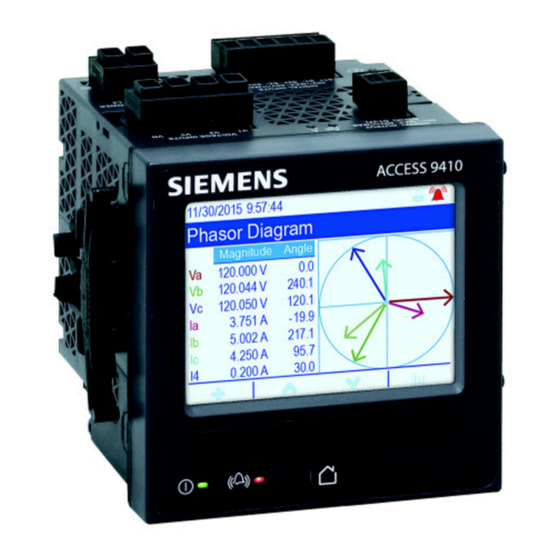
Assistant should only be undertaken by those with an advanced understanding of ION architecture and their meter’s template. See the Internal email client feature technical note, available from www.usa.siemens.com/pds, for instructions on how to configure your meter to email logged data. See the ION Reference, available from www.usa.siemens.com/pds, for more information about ION architecture and ION modules. -
Page 120: Event Log Overview
Event log data example: NOTE: This example is representative only, and your meter’s event log may appear different than shown. See the ION Reference, available from www.usa.siemens.com/pds, for more information about the Event Log Controller module and other ION modules. Related Topics •... -
Page 121: Syslog Overview
Logging 9410 series 1. Open advanced configuration mode for your meter. See the ION Setup Help for instructions. 2. Open the EventLogCtl Modules folder and double click EventLogCtl. 3. Enter login credentials as necessary. 4. Click the Setup Registers tab 5. -
Page 122: Waveform Recording Overview
9410 series Logging Syslog severity ION event priority name ION event priority range 2 - Critical condition High 192-255 4 - Warning condition Medium 128-191 5 - Normal but significant 64-127 condition 6 - Informational None 0-63 Waveform recording overview Your meter is able to record voltage and current waveform information. - Page 123 A power event where the voltage or current drops below the nominal value. Swell A power event where the voltage or current rises above the nominal value. See the ION Reference, available from www.usa.siemens.com/pds, for more information on the Waveform Recorder module and its settings. Related Topics •...
-
Page 124: Default Logging Framework
9410 series Logging 6. Configure the waveform recording settings on the Waveform Log Setup screen: a. Set the Waveform Depth to specify the maximum number of waveform records stored on the meter. b. Set the Waveform Format to specify the number of samples per cycle and the number of cycles that are stored in a waveform record. - Page 125 Logging 9410 series Data recorder Log name Depth Interval number Energy/Demand (EgyDmd 3360 (35 days) 900 seconds (15 minutes) Log) Sag/Swell Log Triggered on demand Event Log Triggered on demand 11, 12, 17, 19 - 26, EN50160 Logs varies EN50160 intervals...
- Page 126 9410 series Logging Hist High Log Vll ca high kW tot high Vll avg high kVAR tot high V unbal high kVA tot high Ia high PF lag high Ib high PF lead high Ic high Freq high Hist Low Log...
- Page 127 Logging 9410 series Harm Mean Log I2 THD mean I3 THD mean Harm High Log V1 THD high I1 K Fac high V2 THD high I2 K Fac high V3 THD high I3 K Fac high I1 THD high I2 THD high...
- Page 128 Voltage interruption duration (all voltages) See the 4-30 Compliance and ION Meters technical note, available from www.usa.siemens.com/pds, for more information about your meter’s 4-30 compliance. Default event log configuration Your meter logs all configuration changes, meter access events, and power system events.
-
Page 129: Advanced Log Setup And Memory Optimization
Info Only. To disable the alarm and the event, set the alarm priority to None. See the ION Reference, available from www.usa.siemens.com/pds, for more information about the Event Log Controller module and event priorities for specific ION modules. -
Page 130: Log Depth Configuration
9410 series Logging Log depth configuration You can change the number of records (depth) stored in the log. Use ION Setup to change the maximum number of records (depth) stored in the log in the meter’s long-term memory. Data logs and circular-format waveform recorders have a minimum depth of 2 records. -
Page 131: Log Buffer Configuration
In order to use this functionality, you must configure the data recorder to be fully buffered. See the Data Recorder module description in the ION Reference, available for download from www.usa.siemens.com/pds, for more information on Insert Outage Records functionality. 7EN05-0336-03... - Page 132 9410 series Logging Example: fully buffered log records replicated from short-term to long-term memory A. Log buffer B. Long-term memory C. Total available space in 8:45:30.000 8:45:30.000 the log buffer (for 8:46:30.000 8:46:30.000 example, 20 records) 8:47:30.000 8:47:30.000 9:02:30.000 9:02:30.000 9:03:30.000...
-
Page 133: Changing Log Interval And Depth Settings Using Ion Setup
Logging 9410 series 8:43:30.000 8:44:30.000 8:43:30.000 8:44:30.000 8:45:30.000 8:45:30.000 8:46:30.000 8:46:30.000 8:47:30.000 8:47:30.000 8:48:30.000 8:48:30.000 8:49:30.000 8:49:30.000 8:50:30.000 8:50:30.000 8:51:30.000 8:54:30.000 8:54:30.000 8:51:30.000 8:52:30.000 8:52:30.000 8:53:30.000 8:53:30.000 8:55:30.000 8:54:30.000 8:54:30.000 A. Log buffer B. Long-term memory C. Record that cannot be logged because log buffer is full (this record is lost) D. -
Page 134: Data Log Memory Calculations
9410 series Logging 4. Select the log you want to edit and click Edit. 5. Set the log depth and log interval as required for your logging needs. • Log Interval: you can change the interval units to seconds, minutes, hours or days. -
Page 135: Inputs / Outputs
Inputs / outputs 9410 series Inputs / outputs I/O Overview Your meter has onboard digital I/O which can be increased by adding optional digital and analog I/O modules to expand your meter’s I/O capabilities. Your meter base has: • 3 digital inputs •... -
Page 136: I/O Option Modules
9410 series Inputs / outputs Onboard input and output ports ION module type ION module Hardware port Port name (ION Description (device label) name label) Digital Output Port D1 Port D1 Form A output Calibration Pulser Wh Pulser -LED kWh Pulse LED... -
Page 137: Option I/O Modules Configuration
Inputs / outputs 9410 series for your energy system. For applications requiring high accuracy, such as energy pulsing to verify accuracy, the digital output on the meter base is recommended. Your meter’s digital and analog outputs may change state during a firmware upgrade. -
Page 138: Analog Inputs
9410 series Inputs / outputs Related Topics • Configuring option module analog inputs using ION Setup • Configuring option module analog outputs using ION Setup • Configuring option module digital inputs using ION Setup • Configuring option module digital outputs using ION Setup... - Page 139 If the sensor’s output range does not match your meter’s hardware limits, you must calculate the full scale and/or zero scale values by analyzing the system. See the ION Reference, available from www.usa.siemens.com/pds, for detailed information about the Analog Input module and full scale and zero scale calculations.
-
Page 140: Analog Outputs
9410 series Inputs / outputs Related Topics • Option I/O modules configuration Analog outputs Analog output applications You can use an analog output to send a signal to an analog-controlled valve to modify a water pipe’s valve position in order to change the flow rate. -
Page 141: Digital Inputs
See the ION Reference, available from www.usa.siemens.com/pds for detailed information about the Analog Output module and full scale and zero scale calculations. Configuring option module analog outputs using ION Setup You can configure option module analog outputs using ION Setup. - Page 142 9410 series Inputs / outputs You can connect an IRIG-B time source to one of meter’s digital inputs for IRIG-B time synchronization; for improved accuracy use the digital inputs on the meter base. For IRIG-B time synchronization, you must configure both the meter’s digital input and the meter’s clock.
-
Page 143: Wages Monitoring
Inputs / outputs 9410 series 3. Navigate to Expansion Module > Option I/O Modules and select the module tab that corresponds to the option module with the digital input you want to configure. 4. Select the digital input channel and click Edit. -
Page 144: Input Metering
9410 series Inputs / outputs Water flow meter (15 kL/pulse) Energy meter with digital input 1 assigned to input metering channel 1 and configured with unit kL (kiloliters) Energy management system with WAGES analysis capabilities Input metering Your meter’s digital inputs can be used to count pulses from transducers and convert the pulses to energy measurements. - Page 145 Inputs / outputs 9410 series 4. Select the input metering channel you want to configure and click Edit. The Input Metering Channel Setup screen is displayed. 5. Select Enabled to enable the input metering feature. 6. Click Select to define which digital input is the pulse source for the input metering channel.
-
Page 146: Digital Outputs
9410 series Inputs / outputs 10. Configure your meter to log the input metering data if required. Parameter Description Pulse Weight Enter the value per pulse. Units Select the measurement units associated with the pulse. NOTE: Include source identification information by entering “@” followed by the source identifier. - Page 147 Inputs / outputs 9410 series 4. Configure the digital output by selecting the parameter and clicking Edit. Parameter Value/range Description Source Digital/Boolean Link this input to the value that drives the state of the digital output. If Source is not linked, the digital output state is driven by the Force ON, Force OFF values.
-
Page 148: Energy Pulsing
9410 series Inputs / outputs 5. Configure the digital output by selecting the parameter and clicking Edit. Parameter Value/Range Description Source Digital/Boolean Link this input to the value that drives the state of the digital output. If Source is not linked, the digital output state is driven by the Force ON, Force OFF values. - Page 149 Inputs / outputs 9410 series 2. Calculate the kWh required per pulse: (0.444 kWh/sec)/(2 pulses per second) = 0.222 kWh/pulse 3. Adjust for the KY giving one pulse per 2 transitions if necessary. (0.222 kWh/pulse)/(2) = 0.111 kWh/pulse 7EN05-0336-03...
-
Page 150: Alarms And Alerts
• Historical: the alarm condition previously existed but the condition has since returned to a non-alarm state. See the ION reference, available from www.usa.siemens.com/pds, for more information about Setpoint, Digital Input and Sag/Swell modules. Standard alarms Standard alarms are setpoint-driven alarms monitor certain behaviors, events or unwanted conditions in your electrical system. - Page 151 Alarms and alerts 9410 series Example of over and under setpoint (standard) alarm operation The meter supports over and under setpoint conditions on standard alarms. A setpoint condition occurs when the magnitude of the signal being monitored crosses the limit specified by the pickup setpoint setting and stays within that limit for a minimum time period specified by the pickup time delay setting.
-
Page 152: Relative Setpoint
Only. Disabling (force off) the digital alarm off will disable all functions of the associated digital input. See the ION Reference, available from www.usa.siemens.com/pds, for more information about the Setpoint and Relative Setpoint module, Digital Input module, Sag/Swell module and Disturbance Analyzer modules. -
Page 153: Alarm Indicators
Alarms and alerts 9410 series Alarm priority Event priority Low (blue) 64 - 127 Info Only (no alarm) 1 - 63 None (no alarm or event) Alarms with priority of Info Only or None are not indicated or displayed. Info Only and None event priority Alarms with a priority of Info Only or None are not shown on the meter’s display, and... -
Page 154: Default Alarms
9410 series Alarms and alerts Alarm Alarm icon Alarm icon flash Alarm LED Meter display Historic low Blue outline bell Flash if not acknowledged • Flash if not No flash acknowledged • Steady if acknowledged No active or Gray solid bell... -
Page 155: Viewing And Acknowledging Alarms Using The Meter's Display
Alarms and alerts 9410 series Parameter Description The date and time when the alarm was acknowledged (only applies to acknowledged alarms). Value Active alarm: The maximum value detected when the alarm was triggered. Historic alarm: The maximum value detected during the duration of the alarm. - Page 156 9410 series Alarms and alerts 4. Enable the alarms you disabled in step 1. Related Topics • Meter setup using your meter’s display Alarm setup You can disable alarms through the display in order to prevent nuisance alarms. Alarm setup...
- Page 157 Alarms and alerts 9410 series You can only enable or disable alarms using the display. Alarm configuration is done using ION Setup. Alarms with a priority less than Low (Info Only or None) are not displayed. You must configure all the parameters related to the alarm for alarm functions to operate.
- Page 158 9410 series Alarms and alerts 4. Select the parameter you want to configure and click Edit. The setup dialog box for that parameter appears. 5. Configure the parameters as required. The values you need to set vary depending on the type of sag/swell alarm you are configuring.
-
Page 159: Alerting
SMTP settings and connecting it via Ethernet to an SMTP mail server in order to send an alert by email. Go to www.usa.siemens.com/pds to see the ION meter alerts technical note for detailed information on creating and configuring alerts, and the ION Reference for detailed information about the Alert module and its operation. -
Page 160: Setpoint Learning Overview
9410 series Alarms and alerts Setpoint learning overview Your meter can learn acceptable ranges or thresholds by monitoring normal operating values to determine what constitutes a voltage sag or swell in order to help identify high and low setpoints. NOTE: To help your meter learn the most accurate values possible, it is important that learning occur during a period of normal operation. - Page 161 Lea rne d s a g limit = 87% Maximum d ura tion remainin g Stab le lear ning time See the ION Reference, available from www.usa.siemens.com/pds, for more information on Sag/Swell, Setpoint and Relative Setpoint modules. Implementing standard alarm setpoint learning using ION Setup You can use ION Setup to implement setpoint learning, which analyzes your power system and recommends settings.
- Page 162 9410 series Alarms and alerts 6. Click Setup. The Alarm Learning Setup screen is displayed. 7. Configure the learning parameters for each setpoint and click Save. 8. Click Start All to begin setpoint learning for all setpoints. – When setpoint learning is in progress, an asterisk is displayed next to the setpoint.
- Page 163 Alarms and alerts 9410 series 7. Click Start to begin sag/swell limit learning. • When setpoint learning is in progress, an asterisk is displayed next to the setpoint. • Click Abort to stop sag/swell limit learning. 8. Apply the learned sag/swell limits.
-
Page 164: Resets
9410 series Resets Resets Meter resets Resets allow you to clear various accumulated parameters stored on your meter or reinitialize the meter or meter accessories. Meter resets clear your meter’s onboard data logs and other related information. Resets are typically performed after you make changes to the meter’s basic setup parameters (such as frequency, VT/PT or CT settings) to clear invalid or obsolete data in preparation for putting the meter into active service. - Page 165 Resets 9410 series Reset Description Harmonics Min/Max Reset Clears all accumulated maximum and minimum harmonics values stored in the meter. Disturbance Count Reset Clears the sag/swell event counter. The sag/swell event counter counts the number of sag/swells that have occurred since power-up or the last reset, to provide power quality information to energy management systems.
- Page 166 9410 series Resets Related Topics • Revenue locking Resets You can perform meter resets using the display. Parameter Description Master Reset • Clears all the cumulative and derived quantities from the meter (including demand, peak demand, energy, revenue and test mode parameters) •...
- Page 167 Resets 9410 series 4. Select the desired tab in the Normal Mode dialog box. Depending on the tab selected, different resets are available. Reset available Energy Master Reset Rolling Demand Peak Reset Master Reset Volts, Amps and Power Master Reset...
-
Page 168: Measurements
9410 series Measurements Measurements Power and power factor The sampled measurements taken at the meter’s voltage and current inputs provide data for calculating power and power factor. In a balanced 3-phase alternating current (AC) power system source, the AC voltage waveforms on the current-carrying conductors are equal but offset by one-third of a period (a phase angle shift of 120 degrees between the three voltage waveforms). - Page 169 Measurements 9410 series (+kVAR, +kVARh) Qu a d ra n t 2 Qu a d ra n t 1 90° PF leading PF lagging Power factor sign convention: Power factor sign convention: IEEE = + IEEE = − IEC = −...
-
Page 170: Power Demand
See the ION Setup online help for instructions on how to configure demand peak and the demand reset lockout period on your meter. See the ION Reference, available from www.usa.siemens.com/pds, for detailed information on how Sliding Window Demand modules measure and calculate demand values. -
Page 171: Wages Monitoring
Measurements 9410 series Examples of sliding window demand This example shows two different ways of configuring a 15-minute demand interval: • Single interval (also called block or timed block): the 15-minute demand interval is defined as a single subinterval with a duration of 15 minutes. -
Page 172: Incremental Energy
9410 series Measurements pulses. An energy management system can then use the information from the meter to perform WAGES analysis. Water flow meter (15 kL/pulse) Energy meter with digital input 1 assigned to input metering channel 1 and configured with unit kL... -
Page 173: Conditional Energy
Measurements 9410 series A. First interval (08:00 to 15:00) B. Second interval (15:00 to 22:00) C. Third interval (22:00 to 24:00) The first incremental energy interval is from 8 am (start time) to 3 pm, and is seven hours long. The second incremental energy interval is from 3 pm to 10 pm, and is also seven hours long. -
Page 174: Trending And Forecasting Overview
9410 series Measurements Conditional energy is accumulated until it is reset. The conditional energy reset date and time information is stored in the meter’s event log. Related Topics • Apparent, active and reactive power (PQS) Configuring conditional energy using ION Setup You can enable and configure conditional energy settings using ION Setup. - Page 175 Measurements 9410 series kW sd del-rec (demand) Freq (frequency) Vll ab I a mean Vll bc I b mean Vll ca I c mean Vll avg I avg mean You can configure the start day of the week for trending and forecasting using ION Setup.
-
Page 176: Power Quality
9410 series Power quality Power quality Power quality overview Your meter measures voltage and current harmonics, and calculates several harmonic distortion values as well as K-factor and crest factor values. You must configure your meter with nominal values for voltage, current and frequency for the power system being monitored in order for the meter to perform power quality calculations. -
Page 177: Voltage Crest Factor
Power quality 9410 series 1. Navigate to Power Quality > Harmonics. The total harmonic distortion (THD) screens are displayed. 2. Press the more button, and select the desired harmonics. The per-phase harmonics are graphically displayed. 3. Press the left and right buttons to move to individual harmonics. The harmonic number, magnitude and angle are displayed. -
Page 178: Harmonic Content Calculations
This is an advanced procedure that should only be performed by users with an advanced knowledge of power quality, ION architecture, and the power system being monitored. See the ION Reference, available from www.usa.siemens.com/pds, for details about the Harmonics Measurement module. Phasors Phasors are used to represent the voltage and current relative magnitude and angles. -
Page 179: Disturbance Direction Detection Overview
Power quality 9410 series Disturbance direction detection overview Your meter has disturbance direction detection capabilities to help you determine the location of a power system disturbance. When a disturbance occurs, the meter analyzes the disturbance information to determine the direction of the disturbance relative to the meter. This analysis includes a confidence level indicating the level of certainty that the disturbance is in the determined direction, and is stored in your meter’s event log. -
Page 180: Comtrade
9410 series Power quality See the ION Reference, available from www.usa.siemens.com/pds, for more detailed information about the Disturbance Direction Detection module. Related Topics • Event log overview COMTRADE Your meter can generate COMTRADE files and store them on the meter’s internal FTP site. -
Page 181: Waveforms On Your Meter's Webpages
Power quality 9410 series Related Topics • Configuring sag/swell logging and waveform recording using ION Setup Waveforms on your meter’s webpages You can use the waveform viewer on the meter’s webpages to view waveforms generated as a result of power quality events. - Page 182 9410 series Power quality A. Select the COMTRADE module to view (COMTRADE_1 is set up by default; you can also set up COMTRADE_2 or COMTRADE_3) B. Select the particular COMTRADE waveform to view C. Show / hide parameters D. View details E.
- Page 183 Power quality 9410 series 5. Click or tap an individual voltage or current channel in the legend to show or hide it in the waveform viewer. – Visible – Hidden 6. Use the bar at the bottom to zoom in / zoom out on a particular section of the waveform, or to scan through the waveform with the selected zoom level.
-
Page 184: Verifying Accuracy
9410 series Verifying accuracy Verifying accuracy Overview of meter accuracy All meters are tested and verified at the factory in accordance with International Electrotechnical Commission (IEC) and American National Standards Institute (ANSI) standards. Your digital power meter typically does not require re-calibration. However, in some installations a final accuracy verification of the meters is required, especially if the meters will be used for revenue or billing applications. -
Page 185: Energy Pulsing
Your meter complies with and meets the requirements of these energy metering standards. For a list of accuracy standards that your meter complies to, contact your local Siemens Industry representative or download the meter brochure from www.usa.siemens.com/pds. Reference device or energy standard... -
Page 186: Verifying Accuracy Test
9410 series Verifying accuracy Meter parameter Value Volts mode 4W-Wye (4 wire Wye) PT/CT correction Disabled Verifying accuracy test The following tests are guidelines for accuracy testing your meter; your meter shop may have specific testing methods. DANGER HAZARD OF ELECTRIC SHOCK, EXPLOSION, OR ARC FLASH Failure to follow these instructions will result in death or serious injury. -
Page 187: Calculate The Number Of Required Pulses
Verifying accuracy 9410 series 4. Connect the control equipment used for counting the standard output pulses using one of these methods: Option Description Energy pulsing LED Align the red light sensor on the standard test bench armature over the energy pulsing LED. -
Page 188: Percentage Error Calculation For Accuracy Verification Testing
NOTE: If accuracy verification reveals inaccuracies in your meter, they may be caused by typical sources of test errors. If there are no sources of test errors present, please contact your local Siemens Industry representative. Typical sources of test errors If you see excessive errors during accuracy testing, examine your test setup and test procedures to eliminate typical sources of measurement errors. - Page 189 Verifying accuracy 9410 series Watt-hour test point Sample accuracy verification test point Full load 100% to 200% of the nominal current, 100% of the nominal voltage and nominal frequency at unity power factor or one (1). Light load 10% of the nominal current, 100% of the nominal voltage and nominal frequency at unity power factor or one (1).
-
Page 190: Revenue Metering
9410 series Revenue metering Revenue metering Revenue metering overview Revenue metering is one of your device’s primary features. The main purpose of a revenue meter is to provide measurements that are within industry-accepted limits for accuracy over a defined range of operating conditions. It also provides adequate protection against unauthorized alteration of these measured quantities. -
Page 191: Revenue Locking
Download the ION Device Template Reference, available from www.usa.siemens.com/pds to view a complete listing of revenue-locked parameters and data. See the meter’s catalog pages, available from www.usa.siemens.com/pds, or consult your local Siemens Industry representative for information about your device, its options and accessories. Related Topics •... -
Page 192: Revenue Locking Your Meter
Power Meter module’s data. See the ION Setup online help, available from www.usa.siemens.com/pds, for instructions on how to configure PT/CT correction on your device. See the ION Reference, available from www.usa.siemens.com/pds, for detailed information about the Instr Xformer Correction (ITC) module and how it applies PT/ CT correction to your device. -
Page 193: Time Of Use
See the ION Setup online help, available from www.usa.siemens.com/pds, for instructions on how to configure time of use on your meter. See the ION Reference, available from www.usa.siemens.com/pds, for a description of the Time of use module and its settings. -
Page 194: Specifications Overview
The information contained in this section is subject to change without notice. You can download updated documentation from www.usa.siemens.com/pds or contact your local Siemens Industry Industry representative for the latest updates. See your device’s installation sheet for specifications related to installation, such as measured current and voltage ranges, inputs/outputs and control power information. - Page 195 Specifications overview 9410 series Measurement accuracy IEC 62053-22 - active energy Class 0.2S IEC 62053-24 - reactive energy Class 0.5S IEC 61557-12 PMD/SD/K70/0.2 and PMD/SS/K70/0.2 Active power (P) IEC 61557-12 Class 0.2 (± 0.2%) Reactive power (Q IEC 61557-12 Class 1 (± 1%) Apparent power (S IEC 61557-12 Class 0.2 (±...
-
Page 196: Environmental Characteristics
9410 series Specifications overview DC control power Operating range 110 to 415 V DC ± 15% Burden (meter only) max. 6 W at 300 V DC Burden (fully optioned meter) 17 W at 300 V DC Ride-through time 100 ms (6 cycles at 60 Hz) min., any condition... -
Page 197: Leds
Specifications overview 9410 series Pollution degree Altitude < 3000 m (9843 ft) Location/mounting Not suitable for wet locations For indoor use only Must be permanently connected and fixed Maximum operating temperature Max temp 948M2DO6DI 948M2AO4AI Digital (2 out, 6 in) Analog (2 out, 4 in) 70 ºC (158 ºF) -
Page 198: Safety
9410 series Specifications overview Safety Safety construction IEC/EN 61010-1 ed.3, CAT III, 400 VLN / 690 V LL UL 61010-1 ed.3 and CSA-C22.2 No. 61010-1 ed.3, CATIII, 347 V LN / 600 V LL IEC/EN 62052-11, Protective Class II Ethernet communications... -
Page 199: Remote Display
Specifications overview 9410 series System types (for MID-compliant • 3-phase 4-wire Wye grounded applications) • 3-phase 3-wire Delta ungrounded Current rating 0.05 – 5(10)A Nominal frequency 50 Hz Energy pulsing LED Pulse weight – 5000 imp/kWh To comply with MID, the meter must be installed in MID certified cabinets rated for IP51 or better. - Page 200 9410 series Specifications overview Data update rate Regular data: 1 second High-speed: 50 – 60 Hz half-cycle Advanced security users Up to 50 users 7EN05-0336-03...
- Page 202 5400 Triangle Parkway Norcross, GA 30092 Siemens Industry, Inc. 5400 Triangle Parkway Norcross, GA 30092 For more information visit www.usa.siemens.com/pds Search for the nearest sales office at www.usa.siemens.com/pds or call 1.800.241.3138 Contact the Power Distribution Solutions (PDS) Service and Support at: Operating hours: 8:00 am —...