Advertisement
Quick Links
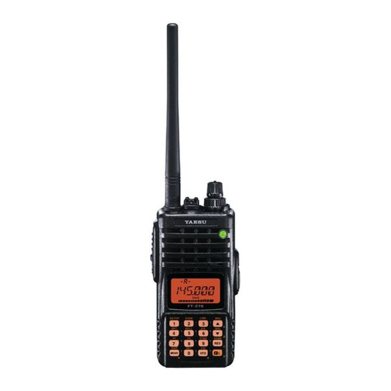
FT-277R
Technical Supplement
©
2010 VERTEX STANDARD CO., LTD.
Specifications ....................................................................................................................................................................2
Exploded View & Miscellaneous Parts .......................................................................................................................3
Block Diagram .................................................................................................................................................................. 5
Circuit Description .......................................................................................................................................................... 7
Alignment ..........................................................................................................................................................................9
Board Units (Schematics, Layouts & Parts)
Main Unit ................................................................................................................................................................... 13
FTD-7 DTMF Paging Unit (Option) ........................................................................................................................ 31
FT-277R Technical Supplement
EH022U91A
Introduction
This manual provides the technical information necessary for servicing the FT-
277R UHF FM Transceiver.
Servicing this equipment requires expertise in handing surface-mount chip compo-
nents. Attempts by non-qualified persons to service this equipment may result in
permanent damage not covered by the warranty, and may be illegal in some coun-
tries.
Two PCB layout diagrams are provided for each double-sided board in this trans-
ceiver. Each side of the board is referred to by the type of the majority of compo-
nents installed on that side ("Side A" or "Side B"). In most cases one side has only
chip components (surface-mount devices), and the other has either a mixture of
both chip and leaded components (trimmers, coils, electrolytic capacitors, ICs, etc.),
or leaded components only.
While we believe the information in this manual to be correct, VERTEX STANDARD
assumes no liability for damage that may occur as a result of typographical or other
errors that may be present. Your cooperation in pointing out any inconsistencies in
the technical information would be appreciated.
The transceiver was assembled using Pb (lead) free solder, based on the RoHS
specification.
Only lead-free solder (Alloy Composition: Sn-3.0Ag-0.5Cu) should be used
for repairs performed on this apparatus. The solder stated above utilizes the
alloy composition required for compliance with the lead-free specification,
and any solder with the above alloy composition may be used.
Contents
VERTEX STANDARD CO., LTD.
4-8-8 Nakameguro, Meguro-Ku, Tokyo 153-8644, Japan
VERTEX STANDARD
US Headquarters
10900 Walker Street, Cypress, CA 90630, U.S.A.
YAESU UK LTD.
Unit 12, Sun Valley Business Park, Winnall Close
Winchester, Hampshire, SO23 0LB, U.K.
VERTEX STANDARD HK LTD.
Unit 5, 20/F., Seaview Centre, 139-141 Hoi Bun Road,
Kwun Tong, Kowloon, Hong Kong
VERTEX STANDARD AUSTRALIA PTY., LTD.
Normanby Business Park, Unit 14/45 Normanby Road
Notting Hill 3168, Victoria, Australia
Important Note
1
Advertisement

Related Manuals for Yaesu FT-277R


Summary of Contents for Yaesu FT-277R
-
Page 1: Table Of Contents
Contents Specifications ..................................2 Exploded View & Miscellaneous Parts ........................3 Block Diagram .................................. 5 Circuit Description ................................7 Alignment ..................................9 Board Units (Schematics, Layouts & Parts) Main Unit ................................... 13 FTD-7 DTMF Paging Unit (Option) ........................31 FT-277R Technical Supplement... -
Page 2: Specifications
450 mW @ 8 Ω for 10 % THD (EXT SP Jack) (@ 7.5 V) Specifications are subject to change without notice, and are guaranteed within the 430 MHz amateur band only. Frequency ranges will vary according to transceiver version; check with your dealer. FT-277R Technical Supplement... -
Page 3: Exploded View & Miscellaneous Parts
Exploded View & Miscellaneous Parts RA1127500 RA1203900 NAME PLATE (YAESU) WINDOW (FT-277R) RA0304300 WASHER RA111430A DOUBLE FACE RA0577600 EXT CAP CP8517003 PANEL ASSY (FT-277R) RA057840A RING NUT RA1113200 RA008920C PANEL (FT-277R) O RING RA0087900 RA057710A HOLDER SPECIAL NUT RA046760A RA057700A... - Page 4 Exploded View & Miscellaneous Parts Note FT-277R Technical Supplement...
-
Page 5: Block Diagram
Block Diagram FT-277R Technical Supplement... - Page 6 Block Diagram FT-277R Technical Supplement...
-
Page 7: Circuit Description
SQL knob. made up of X1002 is divided by the reference frequency While no carrier is received, pin 71 of Q1001 divider section of Q1003 (MB15A01PFV1) into 2340 or FT-277R Technical Supplement... - Page 8 This pulse is integrated by the charge pump and loop filter of D1012 (DA221) into a control volt- age (VCV) to control the oscillation frequency of the VCO. FT-277R Technical Supplement...
-
Page 9: Alignment
Alignment Introduction Required Test Equipment The FT-277R is carefully aligned at the factory for the The following test equipment (and familiarity with its specified performance across the amateur band. Realign- use) is necessary for complete realignment. Correction of ment should therefore not be necessary except in the event problems caused by misalignment resulting from use of of a component failure. - Page 10 Test Setup Entering the Alignment Mode Set up the test equipment as shown below for transceiver Alignment of the FT-277R is performed using a front panel alignment. software-based procedure. To perform alignment of the transceiver, it must first be placed in the “Alignment Mode,”...
- Page 11 DIAL knob so that the DC volt- 4. Increase the Transmit power level to “MID.” 5. Press the [ F/W ] key to recall the alignment parameter meter reaches maximum deflection. The FT-277R RF Front-end has a broad bandwidth. Therefore, prior to “A2 PWR.xxx.”...
- Page 12 [ ( MHz )] key. 2. The next time the transceiver is turned on, press and hold in the [ VFO ( PRI )] key turning the radio on. Once the radio is on, release the key. normal operation may resume. FT-277R Technical Supplement...
-
Page 13: Main Unit
1.95 V 2.73 V 1.95 V 13.8 V 3.30 V 1.97 V EAION (0V) 5.08 V TX: 2.62 V 2.62 V 1.53 V @CHG 1.48 V @CHG (PWR "OFF") EXT DC IN 13.8V 0.91 V @CHG (PWR "OFF") FT-277R Technical Supplement... - Page 14 MAIN Unit Note FT-277R Technical Supplement...
- Page 15 2SD1664 (DA) KRA304E-RTK/P KRC404E-RTK/P BD4845FVE DA221 (K) DAN222 (N) (Q1030,1031,1032, (Q1063, 1078) (Q1035, 1038, 1039, 1042, (Q1067) (Q1033,1043,1058,1071) (Q1020, 1021,1029,1044,1045, (Q1006) (D1025) (D1024) 1034,1040,1059) 1061, 1062, 1064, 1065, 1057,1068) 1069, 1076, 1077, 1079) 2SC4915 (QY) (Q1024) FMMTL718TA (Q1041) FT-277R Technical Supplement...
- Page 16 (Q1018, 1036) (Q1028,1052,1055,1060,1066, (Q1056) (Q1022, 1023) (Q1027,1054,1084) (Q1015,1025,1026,1047, (Q1007) (Q1080) (D1012, 1030) 1072,1073,1081,1082) 1048,1049,1051, NJM2591V KTA2014E-GR-RTK/P 1070,1075) (Q1004) (Lot.6-) 2SC4915 (QY) (Q1018, 1036) (Q1016) 2SC5006 (73) (Q1011, 1012, 1013, 1014,1017) LM2902PWR BU2090FS DAN222 (N) (Q1046, 1074) (Q1005) (D1029) FT-277R Technical Supplement...
- Page 17 0.047uF GRM155B11A473KA01D K22108801 C 1071 CHIP CAP. 47pF GRM1552C1H470JZ01D K22178228 C 1072 CHIP TA.CAP. 10uF TEESVA1A106M8R K78100028 C 1073 CHIP CAP. 0.001uF GRM188B11H102KA01D K22174821 C 1074 CHIP CAP. 0.001uF GRM155B11H102KA01D K22178809 C 1075 CHIP CAP. GRM188F11A105ZA01D K22105001 FT-277R Technical Supplement...
- Page 18 C 1148 CHIP CAP. 680pF GRM155B11H681KA01D K22178807 C 1149 CHIP CAP. 0.001uF GRM155B11H102KA01D K22178809 C 1150 CHIP CAP. 0.01uF GRM36B103K16PT K22128804 C 1150 CHIP CAP. 0.01uF GRM155B11E103KA01D K22148834 11- B C 1151 CHIP CAP. 0.01uF GRM36B103K16PT K22128804 FT-277R Technical Supplement...
- Page 19 CHIP CAP. 0.22uF GRM188B11A224KA01D K22104801 C 1205 CHIP TA.CAP. 22uF 6.3V TEESVA0J226M8R K78080047 C 1205 CHIP TA.CAP. 22uF 6.3V TEESVA20J226M8R K78080088 11- A C 1206 CHIP CAP. 0.001uF GRM155B11H102KA01D K22178809 C 1207 CHIP CAP. 0.022uF GRM155B11C223KA01D K22128806 FT-277R Technical Supplement...
- Page 20 GRM155B11A104KA01D K22108802 C 1264 CHIP CAP. 0.1uF GRM155B11A104KA01D K22108802 C 1265 CHIP CAP. 0.1uF GRM155B11A104KA01D K22108802 C 1266 CHIP CAP. 0.1uF GRM155B11A104KA01D K22108802 C 1267 CHIP TA.CAP. 47uF SK7-0G476M-RA K78060048 C 1268 CHIP CAP. 0.001uF GRM155B11H102KA01D K22178809 FT-277R Technical Supplement...
- Page 21 D 1046 19-213/S2C-AN1P2B/3T G2071096 D 1047 19-213/S2C-AN1P2B/3T G2071096 D 1048 19-213/S2C-AN1P2B/3T G2071096 D 1049 19-213/S2C-AN1P2B/3T G2071096 D 1050 19-213/S2C-AN1P2B/3T G2071096 D 1051 19-213/S2C-AN1P2B/3T G2071096 D 1052 DIODE RB751S-40TE61 G2070850 DS1001 LCD 20667TF-F G6090166 FB1001 FERRITE BEADS BLM15AG121SN1D L1690843 FT-277R Technical Supplement...
- Page 22 G3070075 Q 1015 TRANSISTOR KRC404E-RTK/P G3070355 Q 1016 TRANSISTOR 2SC4915-O(TE85L.F) G3349158O Q 1017 TRANSISTOR 2SC5006-T1 G3350068 Q 1018 TRANSISTOR 2SA1774 TL R G3117748R Q 1018 TRANSISTOR KTA2014E-GR-RTK/P G3070353 Q 1019 LM2904PWR G1094010 : Please contact Vertex Standard FT-277R Technical Supplement...
- Page 23 G3070354 Q 1059 TRANSISTOR 2SA1774 TL R G3117748R Q 1059 TRANSISTOR KTA2014E-GR-RTK/P G3070353 Q 1060 TRANSISTOR 2SC4617 TL R G3346178R Q 1060 TRANSISTOR KTC4075E-GR-RTK/P G3070356 Q 1061 TRANSISTOR 2SC4617 TL R G3346178R Q 1061 TRANSISTOR KTC4075E-GR-RTK/P G3070356 FT-277R Technical Supplement...
- Page 24 100k 1/16W RMC1/16S 104JTH J24189049 R 1030 CHIP RES. 1/16W RMC1/16S 471JTH J24189021 R 1031 CHIP RES. 1/16W RMC1/16S 471JTH J24189021 R 1032 CHIP RES. 1/16W RMC1/16S 153JTH J24189039 R 1032 CHIP RES. 1/16W 0.5% RR0510R-153-D J24189147 FT-277R Technical Supplement...
- Page 25 1/16W RMC1/16S 153JTH J24189039 R 1112 CHIP RES. 1/16W RMC1/16S 102JTH J24189025 R 1113 CHIP RES. 1/16W RMC1/16S 103JTH J24189037 R 1114 CHIP RES. 5.6k 1/16W RMC1/16S 562JTH J24189034 R 1115 CHIP RES. 1/16W RMC1/16S 103JTH J24189037 FT-277R Technical Supplement...
- Page 26 RMC1/16S 474JTH J24189057 R 1182 CHIP RES. 470k 1/16W RMC1/16S 474JTH J24189057 R 1183 CHIP RES. 1/16W RMC1/16S 223JTH J24189041 R 1184 CHIP RES. 1/16W RMC1/16S 333JTH J24189043 R 1185 CHIP RES. 4.7k 1/16W RMC1/16S 472JTH J24189033 FT-277R Technical Supplement...
- Page 27 RMC1/16S 154JTH J24189051 R 1253 CHIP RES. 470k 1/16W RMC1/16S 474JTH J24189057 R 1254 CHIP RES. 150k 1/16W RMC1/16S 154JTH J24189051 R 1255 CHIP RES. 1/16W RMC1/16S 683JTH J24189047 R 1256 CHIP RES. 390k 1/16W RMC1/16S 394JTH J24189056 FT-277R Technical Supplement...
- Page 28 CHIP RES. 1/16W RMC1/16S 473JTH J24189045 R 1330 CHIP RES. 1/16W RMC1/16S 102JTH J24189025 R 1331 CHIP RES. 1/16W RMC1/16S 102JTH J24189025 R 1332 CHIP RES. 1/16W RMC1/16S 102JTH J24189025 R 1333 CHIP RES. 1/16W RMC1/16S 471JTH J24189021 FT-277R Technical Supplement...
- Page 29 XTAL XVNBAI 11.7MHz 11.7MHz H0103311 XF1001 XTAL FILTER MF47R2 47.25MHZ H1102347 MIC HOLDER RUBBER RA0578200 LIGHT GUIDE (LCD) RA058040A LIGHT GUIDE (LCD) RA1136800 LIGHT GUIDE (LCD) RA113680A REFLECTOR SHEET RA0580500 INTER CONNECTOR (LCD) RA0580700 TERMINAL PLATE RA0698700 FT-277R Technical Supplement...
- Page 30 MAIN Unit Parts List Note DESCRIPTION VALUE TOL. MFR'S DESIG VXSTD P/N VERS. LOT SIDE LAY ADR FT-277R Technical Supplement...
-
Page 31: Dtmf Paging Unit (Option)
FTD-7 DTMF Paging Unit (Option) Circuit Diagram Parts Layout (Side A) (Side B) BU8872FS 2SC4617 (BR) (Q6001) (6003) DTA144EE (16) DTC144EE (26) (Q6002, 6005) (Q6004) FT-277R Technical Supplement... - Page 32 CHIP RES. 4.7k 1/16W RMC1/16S 472JTH J24189033 R 6008 CHIP RES. 1/16W RMC1/16S 103JTH J24189037 R 6009 CHIP RES. 1/16W RMC1/16S 473JTH J24189045 R 6010 CHIP RES. 1/16W RMC1/16S 473JTH J24189045 X 6001 XTAL CSA-309 4.194304MHz 4.194304MHZ H0102987 FT-277R Technical Supplement...
- Page 34 Copyright 2010 VERTEX STANDARD CO., LTD. All rights reserved No portion of this manual may be reproduced without the permission of VERTEX STANDARD CO., LTD. FT-277R Technical Supplement...