Table of Contents
Advertisement
weslo.com
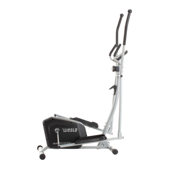
Model No. WLEL19921.0
Serial No.
Write the serial number in the space
above for reference.
Serial
Number
Decal
REGISTER YOUR
PRODUCT
To register your product and
activate your warranty today,
go to my.weslo.com.
CUSTOMER CARE
For service at any time, go to
support.weslo.com.
Or call 1-866-699-3756
Mon.–Fri. 6 a.m.–6 p.m. MT
Sat. 8 a.m.–12 p.m. MT
Please do not contact the store.
CAUTION
Read all precautions and
instructions in this manual before
using this equipment. Keep this
manual for future reference.
USER'S MANUAL
Advertisement
Table of Contents

Related Manuals for Weslo MOMENTUM G4.1


Summary of Contents for Weslo MOMENTUM G4.1
- Page 1 Number Decal REGISTER YOUR PRODUCT To register your product and activate your warranty today, go to my.weslo.com. CUSTOMER CARE For service at any time, go to support.weslo.com. Or call 1-866-699-3756 Mon.–Fri. 6 a.m.–6 p.m. MT Sat. 8 a.m.–12 p.m. MT Please do not contact the store.
-
Page 2: Table Of Contents
If a decal is missing or illegible, see the front cover of this manual and request a free replacement decal. Apply the decal in the location shown. Note: The decal(s) may not be shown at actual size. WESLO is a registered trademark of ICON Health & Fitness, Inc. -
Page 3: Important Precautions
IMPORTANT PRECAUTIONS WARNING: To reduce the risk of serious injury, read all important precautions and instructions in this manual and all warnings on your elliptical before using your elliptical. ICON assumes no responsibility for personal injury or property damage sustained by or through the use of this product. - Page 4 STANDARD SERVICE PLANS...
-
Page 5: Before You Begin
BEFORE YOU BEGIN Thank you for selecting the revolutionary WESLO ® reading this manual, please see the front cover of this MOMENTUM G 4.1 elliptical. The MOMENTUM G 4.1 manual. To help us assist you, note the product model elliptical provides an impressive selection of features number and serial number before contacting us. -
Page 6: Part Identification Chart
PART IDENTIFICATION CHART Use the drawings below to identify the small parts needed for assembly. The number in parentheses below each drawing is the key number of the part, from the PART LIST near the end of this manual. The number following the key number is the quantity needed for assembly. -
Page 7: Assembly
Assembly may be easier if you have a set of wrenches. To avoid damaging parts, do not use • To identify small parts, see page 6. power tools. 1. Go to my.weslo.com on your computer and register your product. • documents your ownership • activates your warranty •... - Page 8 3. Attach the Front Stabilizer (3) to the Frame (1) with two M8 x 65mm Carriage Bolts (73), two M8 Curved Washers (65), and two M8 Acorn Nuts (82); insert both Carriage Bolts, and then tighten the Acorn Nuts. 4. While a second person holds the Upright (2) near the Frame (1), connect the Upright Wire (49) to the Reed Switch Wire (7).
- Page 9 5. Insert the excess wire and cable into the Frame (1). Tip: Avoid pinching the wires and the cables. Slide the Upright (2) onto the Frame (1). Attach the Upright (2) with two M8 x 65mm Bolts (75), four M8 Curved Washers (65), two M8 Split Washers (89), and two M8 Locknuts (84);...
- Page 10 7. Attach the Water Bottle Holder (41) to the Upright (2) with two M4 x 16mm Flange Screws (55); start both Flange Screws, and then tighten them. 8. Identify the Right Lower Arm (11) with the attached Right Pedal Arm (15). Using a plastic bag to keep your fingers clean, apply a generous amount of the included grease to the right axle on the Upright (2).
- Page 11 9. Identify the Right 1/2" x 110mm Bolt (70) and the Right 1/2 " Nut (85). Apply grease to the Right Bolt. Attach the Right Pedal Arm (15) to the right side of the Crank (18) with the Right 1/2 " x 110mm Bolt (70), an M16 Wave Washer (9), an M13 Washer (69), and the Right 1/2 "...
- Page 12 11. Orient the Right Pedal (33) as shown, and attach it to the Right Pedal Arm (15) with two M10 x 45mm Bolts (76), two M10 Washers (72), and two M10 Locknuts (83); insert both Bolts, and then tighten the Locknuts. Attach the Left Pedal (not shown) to the Left Pedal Arm (not shown) in the same way.
- Page 13 13. The Console (5) can use two AAA batteries (not included); alkaline batteries are recommended. Do not use old and new batteries together or alkaline, standard, and rechargeable batter- ies together. IMPORTANT: If the Console has been exposed to cold temperatures, allow it to warm to room temperature before insert- ing batteries.
-
Page 14: How To Use The Elliptical
HOW TO USE THE ELLIPTICAL HOW TO MOVE THE ELLIPTICAL HOW TO USE THE ELLIPTICAL Stand in front of the elliptical, hold the upright (A), and To mount the elliptical, hold the upper arms (D) or the place one foot against one of the wheels (B). Next, pull handlebars (E) and step onto the pedal (F) that is in on the upright and have a second person lift the rear the lower position. - Page 15 HOW TO ADJUST THE PEDALING RESISTANCE HOW TO LEVEL THE ELLIPTICAL To increase the resistance of the pedals, turn If the elliptical the resistance knob (G) clockwise; to decrease the rocks slightly on resistance, turn the knob counterclockwise. your floor during use, turn one or both of the leveling caps (H)
-
Page 16: How To Use The Console
HOW TO USE THE CONSOLE CONSOLE DIAGRAM HOW TO USE THE CONSOLE Make sure that batteries (not included) are installed in the console (see assembly step 13 on page 13). If there is a sheet of plastic on the console, remove the plastic. -
Page 17: Fcc Information
FCC INFORMATION This equipment has been tested and found to comply with the limits for a Class B digital device, pursuant to part 15 of the FCC Rules. These limits are designed to provide reasonable protection against harmful interference in a residential installation. This equipment generates, uses, and can radiate radio frequency energy and, if not installed and used in accordance with the instructions, may cause harmful interference to radio communications. -
Page 18: Maintenance And Troubleshooting
MAINTENANCE AND TROUBLESHOOTING MAINTENANCE HOW TO ADJUST THE REED SWITCH Regular maintenance is important for optimal If the console does not display correct feedback, the performance and to reduce wear. Inspect and reed switch should be adjusted. properly tighten all parts each time the elliptical is used. - Page 19 HOW TO ADJUST THE DRIVE BELT If you can feel the pedals slip while you are pedaling, even when the resistance is at the highest level, the drive belt may need to be adjusted. See assembly step 9 on page 11. Remove the Right Pedal Arm (15) from the right arm of the Crank (18).
-
Page 20: Exercise Guidelines
EXERCISE GUIDELINES Aerobic Exercise—If your goal is to strengthen your WARNING: cardiovascular system, you must perform aerobic Before beginning this exercise, which is activity that requires large amounts or any exercise program, consult your physi- of oxygen for prolonged periods of time. For aerobic cian. -
Page 21: Part List
PART LIST Model No. WLEL19921.0 R0521A Key No. Qty. Description Key No. Qty. Description Frame Upright Wire Upright M6 Locknut Front Stabilizer M4.2 x 20mm Self-tapping Screw Rear Stabilizer M4.2 x 20mm Screw Console M8 x 16mm Screw Handlebar M8 x 60mm Bolt Reed Switch/Wire M4 x 16mm Flange Screw Clamp... -
Page 22: Exploded Drawing
EXPLODED DRAWING A Model No. WLEL19921.0 R0521A... - Page 23 EXPLODED DRAWING B Model No. WLEL19921.0 R0521A...
-
Page 24: Ordering Replacement Parts
ORDERING REPLACEMENT PARTS To order replacement parts, please see the front cover of this manual. To help us assist you, be prepared to provide the following information when contacting us: • the model number and serial number of the product (see the front cover of this manual) •...