Table of Contents
Advertisement
Quick Links
FOR YOUR SAFETY
If you smell gas:
1. Open windows.
2. DO NOT try to light any appliance.
3. DO NOT use electrical switches.
4. DO NOT use any telephone in
your building.
5. Leave the building.
6. Immediately call your local gas
supplier after leaving the building.
Follow the gas supplier’s
instructions.
7. If you cannot reach your gas
supplier, call the Fire Department.
WARNING
Fire Hazard
Do not store or use petrol or other
flammable vapours and liquids in the
vicinity of this or any other appliance.
Some objects will catch fire or explode
when placed close to heater.
Failure to follow these instructions can
result in death, injury or property
damage.
WARNING
Improper installation, adjustment, alteration, service
or maintenance can result in death, injury or property
damage. Read the installation, operation and service
manual thoroughly before installing or servicing
this equipment.
Installation must be done by a registered installer/
contractor qualified in the installation and service of
gas/oil-fired heating equipment or your fuel supplier.
Quality in Any Language™
© Copyright 2008 Roberts-Gordon LLC
Installation, Commissioning,
Operation & Service Manual
Please take the time to read and understand
these instructions prior to any installation.
Installer must give a copy of this manual to the owner.
Keep this manual in a safe place in order to provide
your serviceman with necessary information.
Roberts-Gordon Europe Limited
Unit A, Kings Hill Business Park
Darlaston Road, Wednesbury
West Midlands,WS10 7SH UK
Telephone: +44 (0)121 506 7700
Fax: +44 (0)121 506 7701
Service Telephone: +44 (0)121 506 7709
Service Fax: +44 (0)121 506 7702
E-mail: uksales@rg-inc.com
E-mail: export@rg-inc.com
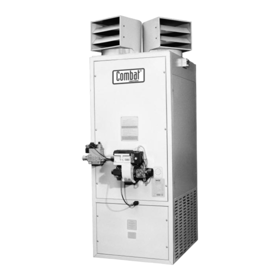
Combat
Cabinet Heaters
OIL-FIRED:
Model POP-ECA
015 to 0100
GAS-FIRED:
Model PGP-ECA
015 to 0100
Installer
Owner
P/N X523 Rev G 10/08
®
Advertisement
Table of Contents
Troubleshooting

Related Manuals for Roberts Gorden Combat POP-ECA 015


![Heater Roberts Gorden Combat UHA[X][S] 100 Installation & Operation Manual](https://static-data2.manualslib.com/product-images/bdb/141375/60x60/roberts-gorden-combat-uha-x-s-100-heater.jpg)


Summary of Contents for Roberts Gorden Combat POP-ECA 015
- Page 1 FOR YOUR SAFETY Combat If you smell gas: ® 1. Open windows. 2. DO NOT try to light any appliance. 3. DO NOT use electrical switches. 4. DO NOT use any telephone in your building. 5. Leave the building. 6. Immediately call your local gas Cabinet Heaters supplier after leaving the building.
-
Page 3: Table Of Contents
TABLE OF CONTENTS SECTION 1: Heater Safety............2 9.11 CCH Wiring Diagram Gas Models 60-100 SECTION 2: Installer Responsibility ........2 (floor standing) ............28 2.1 Clearances to Combustibles ........2 9.12 CCH Wiring Diagram Oil Models 60-100 2.2 Corrosive Chemicals............ 2 (floor standing) ............29 2.3 National Standards and Applicable Codes .... - Page 5 TABLE OF FIGURES Figure 1: Installation Clearances and Clearances to Combustibles ............. 4 Figure 2: Typical Installation of a Gas Fired Cabinet Heater ... 11 Figure 3: Typical Installation of a Oil-Fired Cabinet Heater ..12 Figure 4: Flue Termination ............13 Figure 5: Offset Flues with 135°...
- Page 7 Product Approval ROBERTS GORDON ® appliances have been tested and CE certified as complying with the essential requirements of the Gas Appliance Directive, the Low Voltage Directive, the Electromagnetic Compatibility Directive and the Machinery Directive for use with natural gas and LPG when installed, commissioned and maintained in accordance with these instructions.
-
Page 8: Section 1: Heater Safety
COMBAT ® ABINET EATERS NSTALLATION OMMISSIONING PERATION AND ERVICE ANUAL SECTION 1: HEATER SAFETY Your Safety Is Important to Us! clearances to combustibles. Affix the tag on a wall This symbol is used throughout the near the heater. manual to notify you of possible fire, electrical or burn hazards. -
Page 9: Section 3: Critical Considerations
SECTION 3: C RITICAL ONSIDERATIONS SECTION 3: CRITICAL CONSIDERATIONS 3.1 Basic Information 3.7 Electrical Supply Cabinet heaters are supplied with burners suitable A permanent 230 V, 50 Hz, 1 Ø is required on for on/off operation as standard. As an option, oil- models 15 to 30 and 400 V, 50 Hz, 3 Ø... -
Page 10: Figure 1: Installation Clearances And Clearances To Combustibles
COMBAT ® ABINET EATERS NSTALLATION OMMISSIONING PERATION AND ERVICE ANUAL WARNING Fire Hazard Some objects will catch fire or explode when placed close to heater. Keep all flammable objects, liquids and vapours the required distance away from the heater. Failure to follow these instructions can result in death, injury or property damage. -
Page 11: Section 4: Specifications
SECTION 4: S PECIFICATIONS SECTION 4: SPECIFICATIONS 4.1 PGP & POP Internal Heaters Front View Rear View Side View Side View (all models) (all models) (Models 015 - 050) (Models 060 - 0100) Dimension Data - PGP & POP Internal Heaters Model 015/020 060/070/080... -
Page 12: Pgp & Pop External Heaters
COMBAT ® ABINET EATERS NSTALLATION OMMISSIONING PERATION AND ERVICE ANUAL 4.2 PGP & POP External Heaters Front View Side View Rear View Dimension Data - PGP & POP External Heaters Model 015/020/030 060/070/080 0100 1016 1016 Width (in) 1016 1676 1994 Depth, Cabinet Only (in) -
Page 13: Air Outlet And Flue Arrangements
SECTION 4: S PECIFICATIONS 4.3 Air Outlet and Flue Arrangements 4.3.1 Vertical and Horizontal Heaters - Free Blowing (top view) 0100 060/070/080 015/020 NOTE: Models 015-020 are fitted with 229 mm (9") diameter discharge heads as standard. Models 030-0100 are fitted with 356 mm (14") diameter discharge heads as standard. 4.3.2 Vertical and Horizontal Heaters - Air Outlet Spigots (top view) 015/020/030 060/070/080... -
Page 14: General Technical Data Table (All Models) Appliance Category
COMBAT ® ABINET EATERS NSTALLATION OMMISSIONING PERATION AND ERVICE ANUAL 4.4 General Technical Data Table (all models) Appliance Category II 2H/L 3B/P Model 0100 Electrical Supply* 230 V / 50 Hz / 1 Ø 400 V / 50 Hz / 3 Ø Main Fan Motor Type Direct Drive Belt Drive... -
Page 15: Technical Data - Ecoflam Modulating Burners (All Models - Burner Reference "H")
SECTION 4: S PECIFICATIONS 4.6 Technical Data - Ecoflam Modulating Burners (all models - burner reference "H") Model 0100 (kW) 55.5 73.3 93.2 129.9 162.0 208.0 242.0 275.2 348.5 Maximum Gross Heat Input (Btu/h) x (1000) 189.4 250.1 318.0 443.2 552.7 709.7 825.7... -
Page 16: Technical Data - Ecoflam Oil-Fired Burners (Burner Reference "G")
COMBAT ® ABINET EATERS NSTALLATION OMMISSIONING PERATION AND ERVICE ANUAL 4.7 Technical Data - Ecoflam Oil-Fired Burners (burner reference "G") Model 0100 (kW) 55.5 73.3 93.2 129.9 162.0 208.0 242.0 275.2 348.5 Gross Heat Input (Btu/h) x (1000) 189.4 250.1 318.0 443.2 552.7... -
Page 17: Section 5: Heater Installation
SECTION 5: H EATER NSTALLATION SECTION 5: HEATER INSTALLATION should be placed on a firm, level, non-combustible surface that can support its weight. See Page 5, 5.1 General Section 4.1 for weight details. Heaters are designed for floor standing vertical installation. -
Page 18: Figure 3: Typical Installation Of A Oil-Fired Cabinet Heater
COMBAT ® ABINET EATERS NSTALLATION OMMISSIONING PERATION AND ERVICE ANUAL Figure 3: Typical Installation of a Oil-Fired Cabinet Heater Flues up to 200 mm dia. are fitted with Bird Screens, over 200 mm with a Rain Cap. Minimum Lead Roof Plate Flue Distribution Roof... -
Page 19: Section 6: Flue Installation
SECTION 6: F NSTALLATION SECTION 6: FLUE INSTALLATION 6.1 Flue Installation Figure 6 through Page 14, Figure 9. The joints WARNING between the flue and the roof or wall must be properly sealed. If the flue passes through a wall or ceiling of combustible material it must be enclosed by a sleeve of non-combustible material and be separated from the sleeve by at least a 25 mm air... -
Page 20: Figure 6: Guy Wire
COMBAT ® ABINET EATERS NSTALLATION OMMISSIONING PERATION AND ERVICE ANUAL Figure 6: Guy Wire Figure 8: Flue and Roof Detail Screws, four typical. Over 2 m use Guy Wires Roof Clamp ring Roof Rain Collar Seal Rain Collar joint with high Roof Plate temperature silicon... -
Page 21: Section 7: Air Supply
SECTION 7: A UPPLY SECTION 7: AIR SUPPLY 7.1 Air Supply The main fan requires a minimum free air return path of 1 m per 197 kW of heater output or 0.33 m It is important to ensure adequate air supply at all whichever is greater. -
Page 22: Section 8: Fuel Piping
COMBAT ® ABINET EATERS NSTALLATION OMMISSIONING PERATION AND ERVICE ANUAL SECTION 8: FUEL PIPING 8.1 Connections WARNING Connect the heater to the gas supply, ensuring that the final connections are as follows: • Gas supply pipe is run in medium or heavy gauge tubing in compliance with local and national codes. -
Page 23: Fuel Oil Supply
SECTION 8: F IPING 8.2 Fuel Oil Supply 8.2.4 B. M. Oil Lifter 8.2.1 Fuel Storage Tank Where a gravity feed system cannot be used, a B. M. oil lifter may be used for small installations up to The fuel storage tank should be located outside the the equivalent of a single model 050 on minimum lift building as close as possible to the heater. -
Page 24: Figure 12: Pressurised System Installation - Duplex System
COMBAT ® ABINET EATERS NSTALLATION OMMISSIONING PERATION AND ERVICE ANUAL Figure 12: Pressurised System Installation - Duplex System Pressure Gauge Relief Valve Check Check Valve Valve Stop Stop Pressure Valve Valve Reducing Valve No. 1 No. 2 Pump Pump Fuel Tanks above Stop Stop... -
Page 25: Section 9: Wiring And Electrical Information
SECTION 9: W IRING AND LECTRICAL NFORMATION SECTION 9: WIRING AND ELECTRICAL INFORMATION 9.1 Electrical Supply 9.2.2 Positioning Room Thermostats or Roberts-Gordon Control A 230 V 50 Hz 1 Ø supply is required for all heater Models 015 to 030 connected to the heater terminals A room thermostat or Roberts-Gordon control L1, N and Earth. -
Page 26: Cch Wiring Diagram Gas Models 15-30 (Floor Standing)
COMBAT ® ABINET EATERS NSTALLATION OMMISSIONING PERATION AND ERVICE ANUAL 2. The control will then adjust the burner input If a switch is required to turn on the main fan for continuously to attempt to maintain the ventilation, this must be voltage free, from external temperature set on the control. -
Page 27: Cch Wiring Diagram Oil Models 15-30 (Floor Standing)
SECTION 9: W IRING AND LECTRICAL NFORMATION 9.4 CCH Wiring Diagram Oil Models 15-30 (floor standing) OIL BURNER 6 WAY PLUG PACKAGED BURNER Blue FAN / LIMIT STAT Red / White LIMIT Note: Remote fan control carries full load of fan motor 7 amp inductive TIME/TEMPERATURE CONTROLS... -
Page 28: Cch Wiring Diagram Gas Models 15-30 (Horizontal Mounting)
COMBAT ® ABINET EATERS NSTALLATION OMMISSIONING PERATION AND ERVICE ANUAL 9.5 CCH Wiring Diagram Gas Models 15-30 (horizontal mounting) GAS BURNER 7-WAY PLUG FOR GAS BURNER T1 IS NOT USED B4 = BURNER RUN TO R1 COIL PACKAGED ALL OTHER WIRES SAME AS OIL BURNER BURNER Blue... -
Page 29: Cch Wiring Diagram Oil Models 15-30 (Horizontal Mounting)
SECTION 9: W IRING AND LECTRICAL NFORMATION 9.6 CCH Wiring Diagram Oil Models 15-30 (horizontal mounting) OIL BURNER 6-WAY PLUG PACKAGED BURNER Red / White Blue BURNER RUN SIGNAL R1 COIL 240v LOCKOUT RESET SIGNAL OUTPUTS FROM LOCKOUT SIGNAL BURNER REMOTE LOCKOUT RESET REMOTE LOCKOUT... -
Page 30: Cch Wiring Diagram Gas Models 40-50 (Floor Standing)
COMBAT ® ABINET EATERS NSTALLATION OMMISSIONING PERATION AND ERVICE ANUAL 9.7 CCH Wiring Diagram Gas Models 40-50 (floor standing) GAS BURNER 7-WAY PLUG FAN / LIMIT STAT PACKAGED BURNER LIMIT TIME/TEMPERATURE CONTROLS Red / White Red / White 10 A Red / White FAN CONTROL CONTACTOR... -
Page 31: Cch Wiring Diagram Oil Models 40-50 (Floor Standing)
SECTION 9: W IRING AND LECTRICAL NFORMATION 9.8 CCH Wiring Diagram Oil Models 40-50 (floor standing) OIL BURNER 6-WAY PLUG FAN / LIMIT STAT PACKAGED BURNER LIMIT TIME/TEMPERATURE CONTROLS Red / White Red / White 10 A Red / White FAN CONTROL CONTACTOR Red / White... -
Page 32: Cch Wiring Diagram Gas Models 40-50 (Horizontal Mounting)
COMBAT ® ABINET EATERS NSTALLATION OMMISSIONING PERATION AND ERVICE ANUAL 9.9 CCH Wiring Diagram Gas Models 40-50 (horizontal mounting) FOR GAS BURNER T1 IS NOT USED B4 = BURNER RUN TO R1 COIL ALL OTHER WIRES SAME AS OIL GAS BURNER 7-WAY PLUG BURNER PACKAGED BURNER... -
Page 33: Cch Wiring Diagram Oil Models 40-50 (Horizontal Mounting)
SECTION 9: W IRING AND LECTRICAL NFORMATION 9.10 CCH Wiring Diagram Oil Models 40-50 (horizontal mounting) OIL BURNER 6-WAY PLUG PACKAGED Red / White BURNER BURNER RUN SIGNAL LOCKOUT RESET SIGNAL OUTPUTS FROM LOCKOUT SIGNAL BURNER R1 COIL 240v REMOTE LOCKOUT FOR BURNERS WITH RESET SATRONIC CONTROL BOX... -
Page 34: Cch Wiring Diagram Gas Models 60-100 (Floor Standing)
COMBAT ® ABINET EATERS NSTALLATION OMMISSIONING PERATION AND ERVICE ANUAL 9.11 CCH Wiring Diagram Gas Models 60-100 (floor standing) GAS BURNER 7-WAY PLUG FAN / LIMIT STAT PACKAGED BURNER LIMIT TIME/TEMPERATURE Red / White CONTROLS Red / White 10 A Red / White FAN CONTROL CONTACTOR... -
Page 35: Cch Wiring Diagram Oil Models 60-100 (Floor Standing)
SECTION 9: W IRING AND LECTRICAL NFORMATION 9.12 CCH Wiring Diagram Oil Models 60-100 (floor standing) OIL BURNER 6-WAY PLUG FAN / LIMIT STAT PACKAGED BURNER LIMIT TIME/TEMPERATURE Red / White CONTROLS Red / White 10 A Red / White FAN CONTROL CONTACTOR Red / White... -
Page 36: Cch Wiring Diagram Gas Models 60-100 (Horizontal Mounting)
COMBAT ® ABINET EATERS NSTALLATION OMMISSIONING PERATION AND ERVICE ANUAL 9.13 CCH Wiring Diagram Gas Models 60-100 (horizontal mounting) FOR GAS BURNER T1 IS NOT USED B4 = BURNER RUN TO R1 COIL ALL OTHER WIRES SAME AS OIL GAS BURNER 7-WAY PLUG BURNER Red / White PACKAGED... -
Page 37: Cch Wiring Diagram Oil Models 60-100 (Horizontal Mounting)
SECTION 9: W IRING AND LECTRICAL NFORMATION 9.14 CCH Wiring Diagram Oil Models 60-100 (horizontal mounting) OIL BURNER 6-WAY PLUG Red / White PACKAGED BURNER Blue BURNER RUN SIGNAL Red / White LOCKOUT RESET SIGNAL OUTPUTS R1 COIL 240v Red / White FROM LOCKOUT SIGNAL BURNER... -
Page 38: Final Connections To Ecoflam High/Low Or Modulating Burners (All Models)
COMBAT ® ABINET EATERS NSTALLATION OMMISSIONING PERATION AND ERVICE ANUAL 9.15 Final Connections to Ecoflam HIGH/LOW or Modulating Burners (all models) -
Page 39: Section 10: Commissioning
SECTION 10: C OMMISSIONING SECTION 10: COMMISSIONING Installation, service, commissioning and annual 2. Check the correct fuse size is fitted in the local inspection of the heater must be done by a supply isolator. See Page 8, Section 4.4. contractor qualified in the installation and service of gas or oil-fired heating equipment. -
Page 40: Commissioning The Burner (Gas Heaters)
COMBAT ® ABINET EATERS NSTALLATION OMMISSIONING PERATION AND ERVICE ANUAL Figure 13: Combination Thermostat (all models) See Page 34, Section 10.2.5 and repeat until the burner fires. Set Point 3 10.2.4 Initial Setting Limit Set to 110°C NOTE: Skip this step for models 015 to 030. Once firing, the start gas pressure should be set to the value given in the Data Tables for the burner type and the model concerned (see the burner... -
Page 41: Control - Gas-Fired Heaters
SECTION 10: C OMMISSIONING 3. Check gas flow rate at gas meter. NOTE: If the pressure switch contacts (normally closed) are open, the heater will not start. 10.3 Control - Gas-Fired Heaters For High/Low and modulating burners, follow the 2. The combustion air fan turns on and the pres- general sequence as described below and also sure switch contacts close within the next 5 have extra functional stages related to air damper... -
Page 42: Figure 15: Motor Starter (Models 040 -100 And Thermal Overload (Models 060 - 100)
COMBAT ® ABINET EATERS NSTALLATION OMMISSIONING PERATION AND ERVICE ANUAL Figure 15: Motor Starter (models 040 -100 and Thermal Overload (models 060 - 100) Wire Connecting Line Connections Overload Switch to Coil Contactor Load Connections Thermal Overload Overload Overload Overload Scale Overload Reset Button Connection... -
Page 43: Gas Valves
SECTION 10: C OMMISSIONING Figure 17: Dungs Gas Valve 10.4 Gas Valves appliances and need no further adjustment. When replacing a gas valve, ensure that this device is set Dungs Combination Gas Valve in the fully open position by releasing the locking All model 015 - 030 gas-fired burners operate as screw and turning the "V MAX"... -
Page 44: Commissioning The Burner (Oil Heaters)
COMBAT ® ABINET EATERS NSTALLATION OMMISSIONING PERATION AND ERVICE ANUAL 10.5.1 Pressure Switch 10.6 Commissioning the Burner (Oil Heaters) Check all valves between the fuel tank and the WARNING heater are open, including the fire valve. Ensure that oil is available at the heater inlet and that the air has been vented from the fuel pipe installation. -
Page 45: Turning Off The Heater (All Models)
SECTION 10: C OMMISSIONING 10.7.2 Sequence of Operation pump at the same time by loosening the pump vent port (pump must be running). If the burner goes into The operating sequence is as follows: "lockout" before the pump has vented, wait one With the external controls on and calling for heat, minute, then reset the control box and repeat 10.7 .5 the burner fan and electric ignition will switch on. -
Page 46: Section 11: User Instructions
COMBAT ® ABINET EATERS NSTALLATION OMMISSIONING PERATION AND ERVICE ANUAL SECTION 11: USER INSTRUCTIONS 11.1 User Instructions to low fire. If the temperature rises to the second set point, the burner will turn off. The burner will come ® The COMBAT Cabinet heaters are fully automatic on again at either High or Low fire, depending on the and operate from the external controls fitted on site. -
Page 47: Lighting Instructions (All Models)
SECTION 11: U NSTRUCTIONS 11.4 Simple Fault Finding (all models) Some possible reasons for the heater not operating are: 1. Gas supply not turned ON. 2. Electricity supply not turned ON. 3. The time and/or temperature controls are not 4. The Limit Thermostat may have operated. This Explosion Hazard may be caused by an interruption of the electri- If control locks out, do not make more than 3... - Page 48 COMBAT ® ABINET EATERS NSTALLATION OMMISSIONING PERATION AND ERVICE ANUAL FOR YOUR SAFETY If you smell gas: 1. Open windows. 2. DO NOT try to light any appliance. 3. DO NOT use electrical switches. 4. DO NOT use any telephone in your building.
-
Page 49: Section 12: Servicing
SECTION 12: S ERVICING SECTION 12: SERVICING 12.3 Fan/Motor Assembly Maintenance (all models) 12.1 Servicing Instructions The main fan bearings are permanently sealed and After commissioning, the heater will require do not need lubrication. Before cleaning, turn off fuel maintenance to be carried out annually. If the heater and electrical supply. -
Page 50: Section 13: Conversion Between Fuels
COMBAT ® ABINET EATERS NSTALLATION OMMISSIONING PERATION AND ERVICE ANUAL SECTION 13: CONVERSION BETWEEN FUELS 13.1 General ® All COMBAT Cabinet heaters may be operated on fuel oil, natural gas or propane gas, depending on which burner type has been fitted. Any conversion between fuels must be done by a contractor qualified in the installation and service of gas or oil- fired heating equipment. -
Page 51: Section 14: Troubleshooting
SECTION 14: T ROUBLESHOOTING SECTION 14: TROUBLESHOOTING 14.1 General WARNING Explosion Hazard Installation must be done by a registered installer/ contractor qualified in the installation and service of gas-fired heating equipment or your gas supplier. Failure to follow these instructions can result in death, injury or property damage. -
Page 52: Troubleshooting For Oil Burners (See Manufacture's Instructions)
COMBAT ® ABINET EATERS NSTALLATION OMMISSIONING PERATION AND ERVICE ANUAL 14.2 Troubleshooting for Oil Burners (see manufacture’s instructions) WARNING Electrical Shock Hazard Do not touch ignition components. Voltage from ignition components is high. Failure to follow these instructions can result in death or electrical shock. START Assuming fuel &... -
Page 53: Troubleshooting For Gas Burners (See Manufacturer's Instructions)
SECTION 14: T ROUBLESHOOTING 14.3 Troubleshooting for Gas Burners (see manufacturer’s instructions) WARNING Electrical Shock Hazard Do not touch ignition components. Voltage from ignition components is high. Failure to follow these instructions can START result in death or electrical shock. Assuming fuel &... -
Page 54: Troubleshooting For Flame Supervision System
COMBAT ® ABINET EATERS NSTALLATION OMMISSIONING PERATION AND ERVICE ANUAL 14.4 Troubleshooting for Flame Supervision System The flame supervision system is different for gas-fired and oil-fired heaters but may be tested in a similar way. Gas-fired heaters use a rectification flame probe to monitor the flame. Oil-fired heaters use a photo sensitive cell to monitor the flame. -
Page 55: Troubleshooting For Solenoid Valves Circuit
14.5 Troubleshooting for Solenoid Valves Circuit START Is there pressure on the Is there an electrical supply Fault lies elsewhere. outlet of the valve when the to the valve terminals? Investigate and correct. valve should be closed? Valve faulty. Replace with correct type. Is there an electrical supply Fault lies elsewhere. -
Page 56: Troubleshooting For Main Fan (3 Ø)
14.7 Troubleshooting for Main Fan (3 Ø) START Main fan will not operate following warm up period of heat exchanger. Check for 400 V three phase Fault lies elsewhere. supply at main terminals. Press in white button Check for 230 V at terminals Fault lies elsewhere. -
Page 57: Section 15: Removal And Replacement Parts
SECTION 15: R EMOVAL AND EPLACEMENT ARTS SECTION 15: REMOVAL AND REPLACEMENT a new fuse into the spring clips. To replace the holder, remove the fuse, pull off the two tag PARTS connectors from either end, and then unscrew the See warnings and notes on Page 43, Section 12 central screw. -
Page 58: Figure 22: Combination Fan/Limit Thermostat
COMBAT ® ABINET EATERS NSTALLATION OMMISSIONING PERATION AND ERVICE ANUAL 5. Check the correct rotation of the fan as on Page 33, Section 10.1.5. NOTE: The direct drive fan unit motor can only be replaced as a complete fan/motor assembly. Figure 22: Combination Fan/Limit Thermostat WARNING Fire Hazard... -
Page 59: Section 16: Parts List
SECTION 16: P ARTS SECTION 16: PARTS LIST The following items are recommended as spares which may be required during routine service and replacement of the air heater. There is also a list of parts in the burner manufacturer’s manual which relates to the parts required for the packaged burner fitted to the heater. - Page 62 Attach this information to the wall near the ROBERTS GORDON ® heater ® Read the Installation, Commissioning, Operation and Service Manual thoroughly before installation, operation or service. WARNING OPERATING INSTRUCTIONS 1. STOP! Read all safety instructions on this information sheet. 2.