Sign In
Upload
Manuals
Brands
Roberts Gorden Manuals
Heater
Combat PGP-ECA 040
Roberts Gorden Combat PGP-ECA 040 Manuals
Manuals and User Guides for Roberts Gorden Combat PGP-ECA 040. We have
1
Roberts Gorden Combat PGP-ECA 040 manual available for free PDF download: Installation, Commissioning, Operation & Service Manual
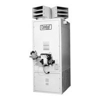
Roberts Gorden Combat PGP-ECA 040 Installation, Commissioning, Operation & Service Manual (62 pages)
Cabinet Heaters, OIL/GAS-FIRED
Brand:
Roberts Gorden
| Category:
Heater
| Size: 4.7 MB
Table of Contents
Table of Contents
3
SECTION 1: Heater Safety
8
SECTION 2: Installer Responsibility
8
Clearances to Combustibles
8
Corrosive Chemicals
8
National Standards and Applicable Codes
8
SECTION 3: Critical Considerations
9
Basic Information
9
Location and Suspension
9
Minimum Required Installation Clearances
9
Clearances to Combustibles
9
Ventilation
9
Fuel Supply
9
Electrical Supply
9
Flue
9
Figure 1: Installation Clearances and Clearances to Combustibles
10
SECTION 4: Specifications
11
PGP & POP Internal Heaters
11
PGP & POP External Heaters
12
Air Outlet and Flue Arrangements
13
General Technical Data Table (All Models) Appliance Category
14
Technical Data - Ecoflam ON/OFF Burners
14
L 3B/P
14
(All Models - Burner Reference "C")
14
Technical Data - Ecoflam Modulating Burners (All Models - Burner Reference "H")
15
Technical Data - Ecoflam Oil-Fired Burners (Burner Reference "G")
16
SECTION 5: Heater Installation
17
General
17
Handling
17
Figure 2: Typical Installation of a Gas Fired Cabinet Heater
17
Figure 3: Typical Installation of a Oil-Fired Cabinet Heater
18
SECTION 6: Flue Installation
19
Flue Installation
19
Figure 4: Flue Termination
19
Figure 5: Offset Flues with 135° Bends
19
Figure 6: Guy Wire
20
Figure 7: Socket Direction
20
Figure 8: Flue and Roof Detail
20
Figure 9: Flue and Heater Spigot Joint Detail
20
SECTION 7: Air Supply
21
Air Supply
21
Isolated Equipment Rooms
21
Building Ventilation
21
Distribution Ducting
21
Return Air Ducting
21
SECTION 8: Fuel Piping
22
Connections
22
Figure 10: Gas Connection
22
Fuel Oil Supply
23
Figure 11: B. M. Oil Lifter
23
Figure 12: Pressurised System Installation - Duplex System
24
SECTION 9: Wiring and Electrical Information
25
Electrical Supply
25
Remote Controls
25
CCH Wiring Diagram Gas Models 15-30 (Floor Standing)
26
CCH Wiring Diagram Oil Models 15-30 (Floor Standing)
27
CCH Wiring Diagram Gas Models 15-30 (Horizontal Mounting)
28
CCH Wiring Diagram Oil Models 15-30 (Horizontal Mounting)
29
CCH Wiring Diagram Gas Models 40-50 (Floor Standing)
30
CCH Wiring Diagram Oil Models 40-50 (Floor Standing)
31
CCH Wiring Diagram Gas Models 40-50 (Horizontal Mounting)
32
CCH Wiring Diagram Oil Models 40-50 (Horizontal Mounting)
33
CCH Wiring Diagram Gas Models 60-100 (Floor Standing)
34
CCH Wiring Diagram Oil Models 60-100 (Floor Standing)
35
CCH Wiring Diagram Gas Models 60-100 (Horizontal Mounting)
36
CCH Wiring Diagram Oil Models 60-100 (Horizontal Mounting)
37
Final Connections to Ecoflam HIGH/LOW or Modulating Burners (All Models)
38
SECTION 10: Commissioning
39
Pre-Commission Checks
39
Commissioning the Burner (Gas Heaters)
40
Figure 13: Combination Thermostat (All Models)
40
Control - Gas-Fired Heaters
41
Figure 14: Gas-Fired Heater Control Box Sequence
41
Figure 15: Motor Starter (Models 040 -100 and Thermal Overload (Models 060 - 100)
42
Figure 16: Gas Train Circuit for Dungs Gas Valves
42
Gas Valves
43
Combustion Testing (All Models)
43
Figure 17: Dungs Gas Valve
43
Commissioning the Burner (Oil Heaters)
44
Control - Oil-Fired Heaters
44
Figure 18: Oil-Fired Heaters Control Box Sequence
44
Turning off the Heater (All Models)
45
External Controls
45
Instruction to the User
45
SECTION 11: User Instructions
46
User Instructions
46
Common User Controls (All Models)
46
Figure 19: Heater Operating Sequence
46
Figure 20: Fan/Limit Thermostat
46
Lighting Instructions (All Models)
47
Simple Fault Finding (All Models)
47
SECTION 12: Servicing
49
Servicing Instructions
49
Burner Maintenance
49
Fan/Motor Assembly Maintenance (All Models)
49
Heat Exchanger Maintenance
49
Thermal Insulation
49
Figure 21: Belt Tension
49
SECTION 13: Conversion between FUELS
50
General
50
Burner Conversion
50
SECTION 14: Troubleshooting
51
General
51
Troubleshooting for Oil Burners (See Manufacture's Instructions)
52
Troubleshooting for Gas Burners (See Manufacturer's Instructions)
53
Troubleshooting for Flame Supervision System
54
Troubleshooting for Solenoid Valves Circuit
55
Troubleshooting for Main Fan Circuit (1 Ø)
55
Troubleshooting for Main Fan (3 Ø)
56
SECTION 15: Removal and Replacement Parts
57
Burner Components
57
Direct On-Line Main Fan Starter and Thermal Overload Unit (3 Ø)
57
Control Circuit Fuse (10 or 5 A, 1-1/4" Long Sand Filled)
57
Combination Fan/Limit Thermostat
57
Main Fan Motor (3 Ø Belt Drive)
57
Main Fan Units
57
Figure 22: Combination Fan/Limit Thermostat
58
SECTION 16: Parts List
59
Spare Parts List
59
Advertisement
Advertisement
Related Products
Roberts Gorden Combat PGP-ECA 015
Roberts Gorden Combat PGP-ECA 020
Roberts Gorden Combat PGP-ECA 030
Roberts Gorden Combat PGP-ECA 050
Roberts Gorden Combat PGP-ECA 060
Roberts Gorden Combat PGP-ECA 070
Roberts Gorden Combat PGP-ECA 080
Roberts Gorden Combat PGP-ECA 0100
Roberts Gorden Combat UHA[X][S] 100
Roberts Gorden Combat UHA[X][S] 75
Roberts Gorden Categories
Heater
Heating System
Electric Heater
Gas Heater
Water Pump
More Roberts Gorden Manuals
Login
Sign In
OR
Sign in with Facebook
Sign in with Google
Upload manual
Upload from disk
Upload from URL