Table of Contents
Advertisement
Quick Links
[1]
Safety Precaution For Service Manual ........1-1
[2]
[3]
Specifications...............................................1-2
[4]
Names Of Parts ...........................................1-3
[1]
Disassembly ................................................2-1
[1]
Block Diagram .............................................3-1
[1]
Waveforms Of Servo Circuit ........................4-1
[2]
Voltage.........................................................4-3
Parts marked with "
" are important for maintaining the safety of the set. Be sure to replace these parts with
specified ones for maintaining the safety and performance of the set.
SERVICE MANUAL
MICRO COMPONENT SYSTEM
MODEL
XL-UH4H Micro Component System consisting of
XL-UH4H (main unit) and CP-UH4H (speaker system).
• In the interests of user-safety (Required by safety regula-
tions in some countries) the set should be restored to its
original condition and only parts identical to those specified
be used.
• Note for users in U.K.
Recording and playback of any material may require
consent which SHARP is unable to give. Please refer
particularly to the provisions of Copyright Act 1956, the
Dramatic and Musical Performers Protection Act 1956, the
Performers Protection Acts 1963 and 1972 and to any
subsequent statutory enactments and orders.
CONTENTS
LAYOUT
[1]
Notes On Schematic Diagram .................. 5-1
[2]
Types Of Transistor And LED ................... 5-1
[3]
[1]
Troubleshooting ........................................ 6-1
[1]
Function Table Of IC................................. 7-1
[2]
LCD Display............................................ 7-12
[3]
Wiring Of Primary Supply Leads
(For U.K. Only)........................................ 7-13
This document has been published to be used for after
sales service only.
- 1
The contents are subject to change without notice.
XL-UH4H
No. S7626XLUH4H//
XL-UH4H
Advertisement
Table of Contents

Related Manuals for Sharp XL-UH4H


Summary of Contents for Sharp XL-UH4H
-
Page 1: Table Of Contents
• Note for users in U.K. Recording and playback of any material may require consent which SHARP is unable to give. Please refer particularly to the provisions of Copyright Act 1956, the Dramatic and Musical Performers Protection Act 1956, the Performers Protection Acts 1963 and 1972 and to any subsequent statutory enactments and orders. -
Page 2: Precautions For Using Lead-Free Solder
XL-UH4H PRECAUTIONS FOR USING LEAD-FREE SOLDER 1. Employing lead-free solder "AUDIO, CONTROL, RECTIFIER, CD, MCU, USB PWB" of this model employs lead-free solder. The LF symbol indicates lead-free solder, and is attached on the PWB and service manuals. The alphabetical character following LF shows the type of lead-free solder. -
Page 3: Chapter 1. General Description
[1] Safety Precaution For Service Manual Precaution to be taken when replacing and servicing the Laser Pickup. This product is classified as a CLASS 1 LASER PRODUCT. XL-UH4H XL-UH4H for U.K. Laser Diode Properties Material: AIGaAs Wavelength: 790 nm Emission Duration: continuous Laser Output: max. -
Page 4: Important Service Notes (For U.k. Only)
XL-UH4H [2] Important Service Notes (For U.K. Only) Before returning the unit to the customer after completion of a repair or adjustment it is necessary for the following withstand voltage test to be applied to ensure the unit is safe for the customer to use. -
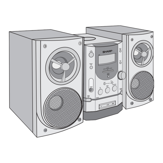
Page 5: Names Of Parts
XL-UH4H [4] Names Of Parts Front panel 1. CD Door 2. On/Stand-by Button 3. Timer Indicator 4. Memory/Disp Button 5. Disc or USB or SD Stop Button 6. Remote Sensor 7. Disc Track Down or Fast Reverse, Tuner Preset Down, Time Down Button 8. - Page 6 XL-UH4H Rear panel 1. AM Loop Aerial Terminal 2. FM 75 Ohms Aerial Socket 3. Speaker Terminals 4. AC Power Lead Speaker system 1. Tweeter 2. Woofer 3. Bass Reflex Duct 4. Speaker Wire Remote control 1. Remote Control Transmitter 2.
-
Page 7: Chapter 2. Mechanism Blocks
XL-UH4H CHAPTER 2. MECHANISM BLOCKS CHAPTER 3. CD-ES700/CD-ES77 CD-ES700/CD-ES77 Service Manual CD-ES700/CD-ES77 Market [1] Caution on disassembly Caution on Disassembly Follow the below-mentioned notes when disassembling the unit and reassembling it, to keep it safe and ensure excel- lent performance: 1. -
Page 8: Chapter 3. Diagrams
XL-UH4H CHAPTER 3. DIAGRAM [1] Block Diagram Figure 1: BLOCK DIAGRAM (1/2) 3 – 1... - Page 9 XL-UH4H Figure 2: BLOCK DIAGRAM (2/2) 3 – 2...
-
Page 10: Chapter 4. Circuit Description
XL-UH4H CHAPTER 4. CIRCUIT DESCRIPTION [1] Waveform Of Servo Circuit MEASURE CH 4 20µs/div Mode < Z1 : 2.5M > 500ms/div Display < Z1 :1 00K > Position Item Setup -0.20div Coupling Delay Setup IC902 19 IC901 24 DC1M 1Cycle Mode... - Page 11 XL-UH4H < Z1 : 2.5M > 500ms/div IC901 31 IC901 33 Freq (C1) IC901 32 31.25000kHz P1sN (C4) 1133 FR-A (C4) 5.891783kHz IC901 43 CH1 10:1 CH2 10:1 CH3 10:1 CH4 10:1 Edge CH4 5.00 V/div 2.00 V/div 2.00 V/div 2.00 V/div...
-
Page 12: Voltage
XL-UH4H [2] IC Voltage U711 U712 U713 IC901 IC902 SST39VF800A 16161A CE2711 SC9641 SA9259 VOLTAGE VOLTAGE VOLTAGE VOLTAGE VOLTAGE VOLTAGE 3.10 3.26 0.00 0.00 3.63 3.42 0.11 2.72 0.00 5.13 4.93 3.42 0.15 2.72 0.00 2.58 4.93 2.53 0.15 0.00 0.12... - Page 13 XL-UH4H Q313 Q314 Q315 Q1101 Q203 Q910 9014 9014 S8050 2061 9014 VOLTAGE VOLTAGE VOLTAGE VOLTAGE VOLTAGE VOLTAGE 0.00 0.00 5.10 7.66 0.00 7.81 0.64 0.64 5.70 8.33 0.00 5.06 0.00 0.00 7.37 11.10 0.00 7.14 Q802 Q801 Q912 Q913...
- Page 14 XL-UH4H -MEMO- 4 – 5...
-
Page 15: Chapter 5. Circuit Schematics And Parts
XL-UH4H CHAPTER 5. CIRCUIT SCHEMATICS AND PARTS LAYOUT [1] Notes On Schematic Diagram • Resistor: • Schematic diagram and Wiring Side of P.W.Board for this model are To differentiate the units of resistors, such symbol as K and M are subject to change for improvement without prior notice. -
Page 16: Wiring Side Of Pwb/Schematic Diagram
XL-UH4H [3] Wiring Side Of PWB/Schematic Diagram Figure 6-1: MAIN SCHEMATIC DIAGRAM AUDIO (1/2) 5 – 2... - Page 17 XL-UH4H Figure 6-2: MAIN SCHEMATIC DIAGRAM AUDIO (2/2) 5 – 3...
- Page 18 XL-UH4H Figure 5-3: MAIN SCHEMATIC DIAGRAM CONTROL & USB 5 – 4...
- Page 19 XL-UH4H Figure 5-4: MAIN SCHEMATIC DIAGRAM RECTIFIER 5 – 5...
- Page 20 XL-UH4H Figure 6-5: CD SCHEMATIC DIAGRAM (1/2) 5 – 6...
- Page 21 XL-UH4H Figure 6-6: CD SCHEMATIC DIAGRAM (2/2) 5 – 7...
- Page 22 XL-UH4H Figure 6-7: MCU SCHEMATIC DIAGRAM (1/2) 5 – 8...
- Page 23 XL-UH4H Figure 6-8: MCU SCHEMATIC DIAGRAM (2/2) 5 – 9...
- Page 24 XL-UH4H Figure 6-9: MCU FLASH SCHEMATIC DIAGRAM (1/2) 5 – 10...
- Page 25 XL-UH4H Figure 6-10: MCU FLASH SCHEMATIC DIAGRAM (2/2) 5 – 11...
- Page 26 XL-UH4H [4] Wiring Side Of PWB Figure 6-11: WIRING SIDE OF AUDIO PWB (1/2) 5 – 12...
- Page 27 XL-UH4H Figure 6-12: WIRING SIDE OF AUDIO PWB (2/2) 5 – 13...
- Page 28 XL-UH4H Figure 6-13: WIRING SIDE OF CONTROL PWB (1/2) 5 – 14...
- Page 29 XL-UH4H Figure 6-14: WIRING SIDE OF CONTROL PWB (2/2) 5 – 15...
- Page 30 XL-UH4H Figure 5-15: WIRING SIDE OF RECTIFIER PWB (TOP) 5 – 16...
- Page 31 XL-UH4H Figure 5-16: WIRING SIDE OF RECTIFIER PWB (TOP) 5 – 17...
- Page 32 XL-UH4H Figure 6-16: WIRING SIDE OF CD PWB (TOP) 5 – 18...
- Page 33 XL-UH4H Figure 6-16: WIRING SIDE OF CD PWB (BOTTOM) 5 – 19...
- Page 34 XL-UH4H Figure 6-17: WIRING SIDE OF MCU PWB (TOP) 5 – 20...
- Page 35 XL-UH4H Figure 6-18: WIRING SIDE OF MCU PWB (BOTTOM) 5 – 21...
- Page 36 XL-UH4H Figure 6-19: WIRING SIDE OF USB PWB (TOP) 5 – 22...
- Page 37 XL-UH4H Figure 6-20: WIRING SIDE OF USB PWB (BOTTOM) 5 – 23...
-
Page 38: Chapter 6. Flowchart
XL-UH4H CHAPTER 6. FLOWCHART [1] Troubleshooting 1. When the CD does not function The CD section may not operate when the objective lens of the optical pickup is dirty. Clean the objective lens, and check the playback operation. When this section does not operate even after the above step is taken, check the follow- ing items. - Page 39 XL-UH4H SC9641 reposit to 600MS Confirm SLDGE CH 4 Check SLED output and < Z1 : 2.5M > 500ms/div Display reposit or not? drive circuit, see Figure 1 Position -0.20div Coupling IC902 19 DC1M Probe 10:1 Offset 0:32 V Start playback without Disc...
- Page 40 XL-UH4H Whether RF wave- Check circuit of SA9618 of form is ok (ftgure4) IC901 12 ˜ 0.2v A>0.2µs Check whether disc is good Whether 56pin output raise any high voltage impulse or Confirm output whether have noise or wrong song...
-
Page 41: Chapter 7. Others
XL-UH4H CHAPTER 7. OTHERS [1] Function Table Of IC U4 92L31012161601 : SDRAM (M12L161A) DQ15 DQ14 DQ13 DQ12 DQ11 DQ10 LDQM N.C/RPU UDQM A10/AP Bank Select Data Input Register LDQM 512 x 16 512 x 16 Column Decoder Latency & Burst Length... - Page 42 XL-UH4H U5 92L31000250100 : CPU ( TS2501 ) ( 1/4 ) VSSIO VDD-USB MODE1 LRCK/GPIO_B22 BCLK/GPIO_B21 UT_RX/IDE_nCS/GPIO_59 UT_TX/GPIO_88 nTRST SDO0/GPIO_A0 ND_nWE/GPIO_B7 SCK0/GPIO_A1 SD_CKE/GPIO_B0 SFRM0/GPIO_A2 VSSI SDI0/GPIO_A3 USBH_CN/GPIO_B29 SDO1/GPIO_A4 USBH_DP/GPIO_B28 VDDI USB_DN/GPIO_B27 VSSI USB_DP/GPIO_B26 SCK1/GPIO_A5 nCS3/nOE3/GPIO_B5 Ts2501 VDDIO nCS/nOE2/GPIO_B4 SFRM1/GPIO_A5 nCS1/nOE1/GPIO_B3...
- Page 43 XL-UH4H U5 92L31000250100 : CPU ( TS2501 ) ( 2/4 ) USB_DP/GPIO_B[28], USB_DN/GPIO_B[27] USBH_DP/GPIO_B[28], USBH_DN/GPIO_B[29] XIN, XOUT Pll & USB1.1 XTIN, XTOUT Boot ROM CLK Generator Host/Device XFILT (4KB) TCO2/GPIO_A[11] TCO5/GPIO_A[8] Timers/ TCO1/GPIO_A[7] Counters TCO4/GPIO_A[4] Generation SRAM TCO0/GPIO_A[3] (64KB) DQM[0:1] / XA[21:20]...
- Page 44 XL-UH4H U5 92L31000250100 : CPU ( TS2501 ) ( 3/4 ) PIN DESCRIPTION Signal Name Shared Signal Pin # Type Description-TS2501 External Memory Interface Pins SD_CKE GPIO_B[0] Input/Output SDRAM Clock Enable signal. Active high. / GPIO_B[0] SD_CLK Input/Output SDRAM Clock / GPO. SD_CLK can be used as a general purpose output.
- Page 45 XL-UH4H U5 92L31000250100 : CPU ( TS2501 ) ( 4/4 ) Signal Name Shared Signal Pin # Type Description-TS2501 Power Pins VDDIO POWER Digital Power for I/O (1.8V ~ 3.3V) VDD_USB POWER Power for USB I/O (3.3V) VDD_OSC POWER Digital Power for Oscillators (1.8V)
- Page 46 XL-UH4H IC901 92L31000964100 : CD SERVO ( SC9641 ) DATA CL16 MCLK_IN SLED DATA_IN VSSP SCLK_IN WCLK_IN SC9641 BCLK MOTO DATA_OUT VDDP SCLK_OUT WCLK_OUT MUTE MODE TRAY_SW SLED_SW CROUT LDON CRIN Servo signal Analog Processor DATA Digital Microcomputer Conversion Connector...
- Page 47 XL-UH4H IC902 92L31000925900 : MOTOR DRIVER ( SC9259 ) FIN (GND) 28 27 26 25 24 23 22 21 20 19 18 17 16 15 SA9259 9 10 11 12 13 14 FIN (GND) LEVER CONVERSION LEVER CONVERSION LEVER CONVERSION...
- Page 48 XL-UH4H IC903 92L31000961800 : CD RF ( SA9618 ) LDON RFRC VREF VREF VREF VREF VREF VREF VREF RFRC VREF Mode 1.24V LDON 3.4K VREF Figure 7-6 BLOCK DIAGRAM OF IC 7 – 8...
- Page 49 XL-UH4H U2 92L31003980031 : FLASH MEMORY ( SST39VF800A ) V SS DQ15 DQ14 DQ13 DQ12 V DD SST39LF / VF800A DQ11 DQ10 V SS SuperFlash X-Decoder Memory Memory Address Address Buffer & Latches Y-Decoder I/O Buffers and Data Latches Control Logic...
- Page 50 XL-UH4H IC501 92L31000731400 : VOLUME CONTROLLER ( SC7314 ) SC7314 LOUDNESS B-OUT B-IN TREBLE Input selector Gain control Audio Bass Treble OUTPUT Vol Control Control Control 24 Lout Mute 27 SCL C BUS Decode + Data Storage Lock 26 SDA...
- Page 51 XL-UH4H U6 92L31000240202 : EEPROM ( AM24LC02 ) ( 1/2 ) PIN DESCRIPTION 24LC02 Name Description A0, A1, A2 Address Inputs Ground Data I/O Clock Input White Protect Power Input U6 92L31000240202 : EEPROM ( AM24LC02 ) ( 2/2 ) start cycle H.V.
-
Page 52: Lcd Display
XL-UH4H [2] LCD Display LCD701 92L22006966425 GRID ASSIGNMENT OUTER DIMENSIONS PATTERN AREA 7 – 12... - Page 53 XL-UH4H -MEMO- 7 – 13...
-
Page 54: Parts Guide
XL-UH4H PARTS GUIDE MICRO COMPONENT SYSTEM XL-UH4H MODEL XL-UH4H Micro Component System consisting of XL-UH4H (main unit) and CP-UH4H (speaker system). CONTENTS [8] RESISTORS [1] INTEGRATED CIRCUITS [9] OTHER CIRCUITRY PARTS [2] TRANSISTORS [10] CABINET PARTS [3] DIODES [11] ACCESSORIES/PACKING PARTS [4] TRANSFORMER [12] P.W.B. - Page 55 XL-UH4H PRICE PART PARTS CODE DESCRIPTION RANK MARK RANK [1] INTEGRATED CIRCUITS IC301 92L21000462800 LA-4628 IC401 92L21000780901 KA7809A IC501 92L31000731400 SC7314 IC701 92L31000409400 CD74HC4094 IC703 92L31000271100 CE2711 IC704 92L21000295000 ME2950 IC705 92L31000162202 HT1622BD IC901 92L31000964100 SC9641 IC902 92L31000925900 SA9259 IC903...
- Page 56 XL-UH4H PRICE PART PARTS CODE DESCRIPTION RANK MARK RANK [5] COILS L701 92L22600100000 CHOKE COIL 10uH L702 92L22600100000 CHOKE COIL 10uH L707 92L22600100000 CHOKE COIL 10uH L901 92L22600260000 CHOKE COIL 26uH L902 92L32612010312 Inductor 10uH L1101 92L22605400000 CHOKE COIL 540uH...
- Page 57 XL-UH4H PRICE PART PARTS CODE DESCRIPTION RANK MARK RANK [7] CAPACITORS C307 92L00406336216 33 UF/16V +-20% C308 92L00407107216 100 UF/16V +-20% C309 92L00405475250 4.7 UF/50V +-20% C310 92L00504154199 0.15 UF/100V +-10% C311 92L00504154199 0.15 UF/100V +-10% C312 92L00504154199 0.15 UF/100V +-10%...
- Page 58 XL-UH4H PRICE PART PARTS CODE DESCRIPTION RANK MARK RANK [7] CAPACITORS C925 92L30230220550 22 PF/50V 0603 +-5% C926 92L00416476216 47 UF/16V +-20% C927 92L30234104250 0.1UF/50V +-20% 0603 C928 92L30232102850 0.001 UF/50V C929 92L00416476216 47 UF/16V +-20% C930 92L00417107216 100 UF/16V +-20%...
- Page 59 XL-UH4H PRICE PART PARTS CODE DESCRIPTION RANK MARK RANK [8] RESISTORS 92L30134104516 100 KOHM 1/16W 92L30133473516 47 KOHM 1/16W 92L30130000516 0 OHM 1/16W 92L30130000516 0 OHM 1/16W 92L30133103516 10 KOHM 1/16W 92L30130000516 0 OHM 1/16W 92L30133103516 10 KOHM 1/16W 92L30130000516...
- Page 60 XL-UH4H PRICE PART PARTS CODE DESCRIPTION RANK MARK RANK [8] RESISTORS R705 92L00100100518 10 OHM 1/8 (AUDIO) R705 92L00103103518 10 KOHM 1/8W (AUDIO) R705 92L00103153518 15 KOHM 1/8W (AUDIO) R706 92L00102102518 1 KOHM 1/8W R715 92L00101101514 100 OHM 1/4W R717...
- Page 61 XL-UH4H PRICE PART PARTS CODE DESCRIPTION RANK MARK RANK [8] RESISTORS R935 92L30133103516 10 KOHM 1/16W R936 92L30133133516 13 KOHM 1/16W R937 92L30133103516 10 KOHM 1/16W R938 92L30133683516 68 KOHM 1/16W R939 92L30133133516 13 KOHM 1/16W R943 92L30132472516 4.7 KOHM 1/16W...
- Page 62 XL-UH4H -MEMO-...
- Page 63 XL-UH4H [10] CABINET PARTS 603x2 PWB-A3 608x2 616x2 608x2 603x2 LEAF PWB-A1 SWITCH 610x2 603x2 PWB-C TUNER PACK PWB-B 605x3 603x8 LED702 LCD701 VR701 PWB-A2 603x2 PWB-D 603x2...
- Page 64 XL-UH4H PRICE PART PARTS CODE DESCRIPTION RANK MARK RANK [10] CABINET PARTS 92L53000100000 FRONT CABINET 92L520X020XX00 BACK CABINET 92L5208470XX00 CD TRAY 92L5208490XX00 CD DOOR 92L5208490XX00 CD DOOR COVER 92L53008040000 DISPLAY LEN 92L53008050000 DECORATION PIECE 92L53001610000 DECORATION 92L50010000000 CD CHUCK A...
- Page 65 XL-UH4H [11] ACCESSORIES/PACKING PARTS PACKING METHOD (FOR U.K. ONLY) 1 FM ANTENNA 92L42000004075 7 SPEAKER BOX 92L669UA30XX00 2 AM ANTENNA 92L65190800000 8 PULP TOP COVER 92L874UA300100 3 REMOTE CONTROL 92L31X000XX010 9 PULP BOTTOM COVER 92L874UA300200 4 OPERATION MANUAL 92L01LUH400040 10 PACKING CASE...
- Page 66 XL-UH4H PRICE PART PARTS CODE DESCRIPTION RANK MARK RANK [11] ACCESSORIES/PACKING PARTS 92L42000004075 FM ANTENNA 92L65190800000 AM ANTENNA 92L31X000XX010 REMOTE CONTROL 92L01LUH400010 OPERATION MANUAL (FOR EUROPE ONLY) 92L01LUH400040 OPERATION MANUAL (FOR U.K.ONLY) 92L02700552000 QUICK GUIDE (FOR U.K. ONLY) 92L669UA30XX00 SPEAKER BOX...
- Page 67 XL-UH4H...
- Page 68 XL-UH4H A0607 SG EX...