Table of Contents
Troubleshooting

Related Manuals for ABB CPS6000-Systems-48V DC Power


Summary of Contents for ABB CPS6000-Systems-48V DC Power
- Page 1 INSTALLATION GUIDE CPS6000-Systems (-48V DC Power) Installation Manual 19 and 23-Inch Systems Product Manual: CC848879683 Issue 2 March 2010 Page 1 © 2021 ABB. All rights reserved. CP:S6000_External Distribution_IG Rev. 1.3...
- Page 2 This page is intentionally left blank. Page 2 © 2021 ABB. All rights reserved. CP:S6000_External Distribution_IG Rev. 1.3...
-
Page 3: Table Of Contents
Appendix A: Pulsar Controller ··········································································································· 39 User Interface Overview ························································································································ 39 Menu Navigation Buttons ······················································································································ 40 System Status Display ··························································································································· 40 Appendix B: Pulsar Wiring Connector Definitions ·········································································· 49 7. Revision ·········································································································································· 53 Page 3 © 2021 ABB. All rights reserved. CP:S6000_External Distribution_IG Rev. 1.3... -
Page 4: Customer Service Contacts
Customer Training ABB Power offers customer training on many Power Systems products. For information call 1-972-244-9288. This number is answered from 8:00 a.m. until 4:30 p.m., Central Time Zone (Zone 6), Monday through Friday. -
Page 5: Safety Statements
The power module provides common-mode protection via a 320V MOV in series with a 2500V gas-discharge device and differential-mode protection via a 320V MOV in series with a 3.5A fuse. Page 5 © 2021 ABB. All rights reserved. CP:S6000_External Distribution_IG Rev. 1.3... - Page 6 Use only fuses provided with safety caps for this type of circuit. Installing telecom-type fuses not equipped with safety caps may result in injury to service personnel. Page 6 © 2021 ABB. All rights reserved. CP:S6000_External Distribution_IG Rev. 1.3...
- Page 7 Batteries are connected in parallel with the output of the rectifiers. Turning off the rectifiers will not necessarily remove power from the bus. Make sure the battery power is also disconnected and/or follow safety procedures while working on any equipment that contains hazardous energy/voltage. Page 7 © 2021 ABB. All rights reserved. CP:S6000_External Distribution_IG Rev. 1.3...
- Page 8 This page intentionally left blank. Page 8 © 2021 ABB. All rights reserved. CP:S6000_External Distribution_IG Rev. 1.3...
-
Page 9: Product Specification
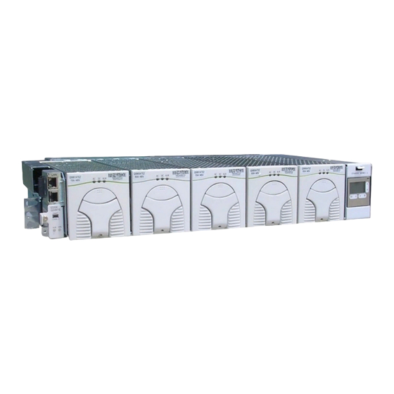
Distribution panels are 7” (4U) high, rectifier shelves and the AC box are 3.5” (2U) high. The system depth is 14”. The rear terminal block option adds an additional 3 inches of depth. Figure 1: System shown with doors open Page 9 © 2021 ABB. All rights reserved. CP:S6000_External Distribution_IG Rev. 1.3... - Page 10 150-275 QS853A 42-58 150-275 42-58 85-150 12.0 QS862A 25/30A 42-58 150-275 QS864A 42-58 150-275 11.8 QS865A 42-58 150-275 14.5 Table 1: Rectifier Specifications Figure 2: Typical Rectifier Numbering Page 10 © 2021 ABB. All rights reserved. CP:S6000_External Distribution_IG Rev. 1.3...
- Page 11 ¼-20 studs on 5/8” centers. The maximum tongue width for breaker connections is 0.68”. Figure 3: DC Distribution Circuit with LVLD Figure 4: DC Distribution Circuit with LVBD or No LVD Page 11 © 2021 ABB. All rights reserved. CP:S6000_External Distribution_IG Rev. 1.3...
- Page 12 This page intentionally left blank. Page 12 © 2021 ABB. All rights reserved. CP:S6000_External Distribution_IG Rev. 1.3...
-
Page 13: Installation
12 (six on each side) 12-24 screws included with the shelf. Weights of the systems is shown in the following table. Page 13 © 2021 ABB. All rights reserved. CP:S6000_External Distribution_IG Rev. 1.3... -
Page 14: Dc Reference (Co) Ground And Chassis Ground
Torque connection to 65 in-lbs. The DC reference ground is connected to the return bus as shown below. Use a 3/8” diameter double-hole lug on 1” centers (Not provided). Figure 5: DC Reference Ground and Chassis Ground Connections Page 14 © 2021 ABB. All rights reserved. CP:S6000_External Distribution_IG Rev. 1.3... - Page 15 Torque screw to 10 in-lbs If feeding 3 positions, At- Install strap to connect adjacent tach wire to center block. Snap loose plastic divider. blocks. Page 15 © 2021 ABB. All rights reserved. CP:S6000_External Distribution_IG Rev. 1.3...
- Page 16 AC per two rectifiers AC per three rectifiers (no jumpers) (1 jumper per 2 blocks) (2 jumpers between 3 blocks) If feeding 3 positions, At- tach wire to center block. Page 16 © 2021 ABB. All rights reserved. CP:S6000_External Distribution_IG Rev. 1.3...
-
Page 17: Battery String And Dc Load Connections
Yellow handle circuit breakers Send alarm in manual off or trip position; mid-trip breakers Black handle circuit breakers Send alarm only in tripped position Figure 6: Selectable DC Distribution Page 17 © 2021 ABB. All rights reserved. CP:S6000_External Distribution_IG Rev. 1.3... - Page 18 Figure 8: Distribution ID Label Figure 7: Circuit Breaker Orientation Page 18 © 2021 ABB. All rights reserved. CP:S6000_External Distribution_IG Rev. 1.3...
- Page 19 901352617 1/4-20 nuts are provided. Torque to 65 in-lbs using 7/16” socket. Secure the Return Load Cable, then the Load Cable. Cable size is 2/0 AWG or less. Page 19 © 2021 ABB. All rights reserved. CP:S6000_External Distribution_IG Rev. 1.3...
- Page 20 Verify wiring polarity at the input of the load equipment. Do not install load fuses until the load equipment is ready to be energized. Note: GMT Module has Current Capacity of 58A. Maximum fuse size is 12A Page 20 © 2021 ABB. All rights reserved. CP:S6000_External Distribution_IG Rev. 1.3...
- Page 21 Jumper 11 next to the relay configuration jumpers. Following are the appropriate settings for negative and positive power plants. For +24V systems with Negative Grounded batteries Pin 1 For -48V systems with Positive Grounded batteries Pin 1 Page 21 © 2021 ABB. All rights reserved. CP:S6000_External Distribution_IG Rev. 1.3...
- Page 22 Dress the field wiring using the tie points next to the upper hinge and out the side of the cabinet. Check to make sure the door can open and close without straining the connectors. Page 22 © 2021 ABB. All rights reserved. CP:S6000_External Distribution_IG Rev. 1.3...
-
Page 23: Battery Monitoring Connections
Figure 9: VT-Probe Connections for Monitoring Battery Temperature Figure 10: VT-Probe Connections for Monitoring Battery Temperature and Voltage Page 23 © 2021 ABB. All rights reserved. CP:S6000_External Distribution_IG Rev. 1.3... - Page 24 TEMPERATURE COMP and verify that the feature Temperature Comp is Enabled. If not, configure and save it appropriately. Additional parameters associated with slope thermal compensation may be set on the controller to customize this feature. Page 24 © 2021 ABB. All rights reserved. CP:S6000_External Distribution_IG Rev. 1.3...
- Page 25 MANAGEMNT and select TEMPERATURE COMP and verify that the feature Temperature Comp is Enabled. If not, configure and save it appropriately. Additional parameters associated with slope thermal compensation may be set on the controller to customize this feature. Page 25 © 2021 ABB. All rights reserved. CP:S6000_External Distribution_IG Rev. 1.3...
-
Page 26: Local Port (Rs-232 / Usb) Connection
Reapply power by reinserting the PWR connection until latched. Verify Server Mode by pressing Menu>Status>Network Settings>Port 1> to find 192.168.2.1 as the network address. Launch the PC’s internet browser and enter 192.168.2.1 in the address bar. Page 26 © 2021 ABB. All rights reserved. CP:S6000_External Distribution_IG Rev. 1.3... - Page 27 Activate changes by removing the latching PWR connection, located on the lower right of the controller, until the LEDs extinguish. Reapply power by reinserting the PWR connection until latched. Verify Client Mode by pressing Menu>Configuration>Communications Ports>Network Settings> to show Client mode. Page 27 © 2021 ABB. All rights reserved. CP:S6000_External Distribution_IG Rev. 1.3...
-
Page 28: Rectifier Installation
CPS shelf. The latch will pop most of the way up when the rectifier is properly seated. Push the latch up into the latched position. Repeat until all rectifiers are installed. Figure 11: Rectifier Installation Page 28 © 2021 ABB. All rights reserved. CP:S6000_External Distribution_IG Rev. 1.3... -
Page 29: Initial Start-Up
55V in 0.1V increments. The factory default setting is 51.0V. Very Low Voltage Alarm indicates an imminent system shutdown due to discharging batteries or low output voltage. The factory default setting is -46.0V. Major Page 29 © 2021 ABB. All rights reserved. CP:S6000_External Distribution_IG Rev. 1.3... - Page 30 <+> or <-> key to adjust the threshold value. Press <ENTER> to save the change. Note that the controller will ask to confirm the corresponding float voltage settings. Page 30 © 2021 ABB. All rights reserved. CP:S6000_External Distribution_IG Rev. 1.3...
- Page 31 Voltage has been set to the desired value Press the Display Menu key to save the change. The voltage range is 42.0 to 56.5 Volts. Factory default is -54.5V. Select Voltage Alarms to set the four Voltage Alarm thresholds. Page 31 © 2021 ABB. All rights reserved. CP:S6000_External Distribution_IG Rev. 1.3...
- Page 32 This page intentionally left blank. Page 32 © 2021 ABB. All rights reserved. CP:S6000_External Distribution_IG Rev. 1.3...
-
Page 33: Troubleshooting
High Voltage Shutdown, Thermal Alarm, Internal Failure AC Fail, PFC Fail, Input Fuse, Missing AC, Low Input AC > 15 ms Current Limit Operation Flashing Communication Loss Flashing Page 33 © 2021 ABB. All rights reserved. CP:S6000_External Distribution_IG Rev. 1.3... -
Page 34: Troubleshooting Chart
Place disconnect switch in ON position. Open manually opened LVD contactor. One or more of the output MAJ, Fuse Major Reset circuit breakers or replace fuse. circuit breakers or fuses Page 34 © 2021 ABB. All rights reserved. CP:S6000_External Distribution_IG Rev. 1.3... - Page 35 AMBER Replace rectifier. (Note 1) rectifier has entered hiccup mode. Batteries have exceeded MIN, Battery High AMBER temperature threshold Call your local field representative. Temperature set by user. Page 35 © 2021 ABB. All rights reserved. CP:S6000_External Distribution_IG Rev. 1.3...
- Page 36 30 controller. seconds, and replacing. (Single Rectifier If problem persists, replace the signaling) rectifier. If problem still persists, call your local field representative. Page 36 © 2021 ABB. All rights reserved. CP:S6000_External Distribution_IG Rev. 1.3...
-
Page 37: Product Warranty
If Seller determines that a Product for which warranty service is claimed is not defective or nonconforming, Customer shall pay Seller all costs of handling, inspecting, testing, and transportation and, if applicable, traveling and related expenses. Page 37 © 2021 ABB. All rights reserved. CP:S6000_External Distribution_IG Rev. 1.3... - Page 38 IMPLIED WARRANTIES, INCLUDING BUT NOT LIMITED TO WARRANTIES OF MERCHANTABILITY AND FITNESS FOR A PARTICULAR PURPOSE. CUSTOMER’S SOLE AND EXCLUSIVE REMEDY SHALL BE SELLER’S OBLIGATION TO REPAIR, REPLACE, CREDIT, OR REFUND AS SET FORTH ABOVE IN THIS WARRANTY. Page 38 © 2021 ABB. All rights reserved. CP:S6000_External Distribution_IG Rev. 1.3...
-
Page 39: Appendix A: Pulsar Controller
The NE843 has six tactile buttons to use to navigate through a structured menu system. The buttons serve multiple purposes depending on the screen a user is at. These functions are summarized below. Page 39 © 2021 ABB. All rights reserved. CP:S6000_External Distribution_IG Rev. 1.3... -
Page 40: Menu Navigation Buttons
High severity. Generally assigned to alarm to indicate a Power affecting condition. Major Alarm Immediate attention required. Medium severity. Generally assigned to alarm to indicate a non-power affecting condition. Attention eventually required. Minor Alarm Page 40 © 2021 ABB. All rights reserved. CP:S6000_External Distribution_IG Rev. 1.3... - Page 41 Pressing the arrow key provides a quick link to temporarily cut-off the audible alarm. Page 41 © 2021 ABB. All rights reserved. CP:S6000_External Distribution_IG Rev. 1.3...
- Page 42 EasyView for local access. The port can also be configured to be used with an external modem. There is also space allocated for a RJ45 or USB receptacle. The LAN (Ethernet) port is located on the con- troller board. Page 42 © 2021 ABB. All rights reserved. CP:S6000_External Distribution_IG Rev. 1.3...
- Page 43 No Active Alarms or No Active Warnings will be displayed when they are no alarms or warnings detected by the controller. Page 43 © 2021 ABB. All rights reserved. CP:S6000_External Distribution_IG Rev. 1.3...
- Page 44 Status Menu Page 44 © 2021 ABB. All rights reserved. CP:S6000_External Distribution_IG Rev. 1.3...
- Page 45 Control / Operations and History Menus Page 45 © 2021 ABB. All rights reserved. CP:S6000_External Distribution_IG Rev. 1.3...
- Page 46 Configuration Menu (part 1) Page 46 © 2021 ABB. All rights reserved. CP:S6000_External Distribution_IG Rev. 1.3...
- Page 47 Configuration Menu (part 2) Page 47 © 2021 ABB. All rights reserved. CP:S6000_External Distribution_IG Rev. 1.3...
- Page 48 This page intentionally left blank. Page 48 © 2021 ABB. All rights reserved. CP:S6000_External Distribution_IG Rev. 1.3...
-
Page 49: Appendix B: Pulsar Wiring Connector Definitions
(Aux_R) Plant Battery Test/ 9 (S) Group Standby (TR) Ret. Return for Plant Battery Test and Group Standby. (GSTR_R) Emergency Power Off Return for EPO input. Ret. (EPO_R) Page 49 © 2021 ABB. All rights reserved. CP:S6000_External Distribution_IG Rev. 1.3... - Page 50 LAN and its standard web browser used to directly access the controller by typing in network address http://192.168.2.1. A connection should never be made between the controller and LAN while the controller is in Server mode. Page 50 © 2021 ABB. All rights reserved. CP:S6000_External Distribution_IG Rev. 1.3...
- Page 51 Page 51 © 2021 ABB. All rights reserved. CP:S6000_External Distribution_IG Rev. 1.3...
- Page 52 LAN. This is generally a permanent connection between the controller and LAN so a Shielded Cat-5 cable is suggested. This page intentionally left blank. Page 52 © 2021 ABB. All rights reserved. CP:S6000_External Distribution_IG Rev. 1.3...
-
Page 53: Revision
7.Revision Rev. Description Date Updated as per template 02/22/2022 Updated page footer; corrected to “Installatiion Guide” 4/17/23 Page 53 © 2021 ABB. All rights reserved. CP:S6000_External Distribution_IG Rev. 1.3... - Page 54 ABB does to third parties or utilization of its contents–in whole or in not accept any responsibility whatsoever for potential errors or parts – is forbidden without prior written consent of ABB. possible lack of information in this document. Copyright© 2021ABB...