Table of Contents
Advertisement
Quick Links
Advertisement
Table of Contents

Related Manuals for ABB CPS3200U


Summary of Contents for ABB CPS3200U
- Page 1 PRODUCT MANUAL Page 1 © 2021 ABB. All rights reserved.
-
Page 2: Table Of Contents
Unpacking Shelf Level Upstream Product ·························································································· 23 Installing and Powering the CP3200U Converter Shelf ···································································· 23 Ground the Shelf······································································································································ 25 Attach the Load Wiring ·························································································································· 25 Set Shelf ID and Attach Alarm Wiring ···································································································27 Page 2 © 2021 ABB. All rights reserved. - Page 3 Appendix B: Alarm Reference Table ····································································································· 57 Appendix C: Operation without a Controller - Alarm Wiring ·························································· 59 CPS3200U Shelf Alarm Card State Table ··························································································· 60 Alarm Card Logical Operation of LEDs and Alarm Relays ································································ 61 12. Revision ········································································································································ 63 Page 3 ©...
-
Page 4: Table Of Figures
Figure 16 Open the Wiring Region of the Fan Shelf ········································································· 30 Figure 17 Alarm Wiring for Fan Shelf ································································································· 31 Figure 18 DC Cabling Fan Trays in CPS3200U Systems ···································································· 31 Figure 19 Cover the Wiring Region of the Fan Shelf ········································································ 32 Figure 20 Fan Tray LEDs ····················································································································... - Page 5 Figure 42 QS930 Fan Shelf Connections and Fuses ········································································ 50 Figure 43 Converter Shelf with Slot Fillers ······················································································ 56 Figure 44 Alarm Card Office Alarm Pinout and Shelf ID ·································································· 59 Figure 45 Alarm Card Office Alarm Cables ······················································································ 59 Page 5 © 2021 ABB. All rights reserved.
-
Page 6: Table Of Tables
Table 5 QS982A Converter LED Information Map ················································································ 45 Table 6 QS982A Converter LED Information Map (visual) ·································································· 46 Table 7 Output Connector Pinout ········································································································· 49 Table 8 Alarm Reference ························································································································· 57 Table 9 Shelf Alarm Card State ············································································································· 60 Page 6 © 2021 ABB. All rights reserved. -
Page 7: Introduction
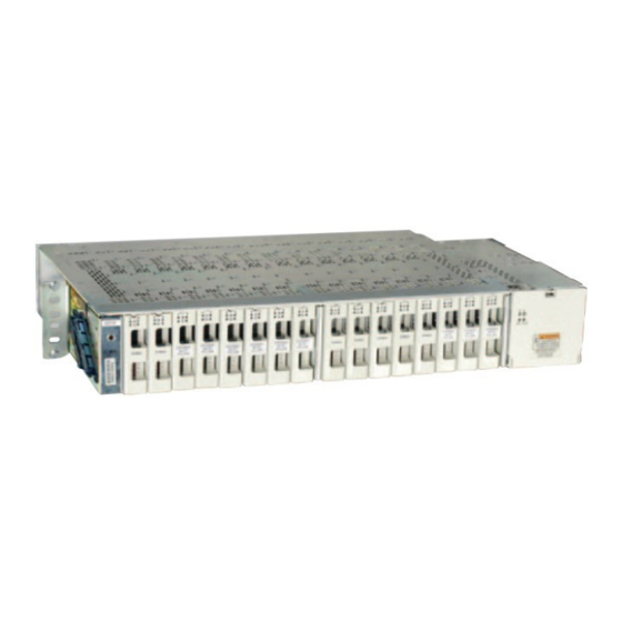
1. Introduction Overview The CPS3200U is the premier upstream dc/dc converter for line powering FTTN networks. The 3200U contains 16 dc/dc converter/limiter cards in a dense 2 RU shelf. Each card contains a pair of independent -48 Vdc input to ±190 Vdc output converters with each output safety limited to 100VA. In addition, each output terminal is safety Ground Fault protected. -
Page 8: Customer Service Contacts
ABB Energy phones are staffed from 7:00 am to 5:00 pm USA Central Time Zone (GMT -6), Monday through Friday, on normal business days. At other times, this number is still available, but for emer- gencies only. -
Page 9: Product Description
The alarm card provides major and minor form C contacts, manages the converters and relays information to a ABB Power CPS6000 family controller using Galaxy Protocol over an RS485 bus. Up to 24 shelves can be controlled and monitored by one CPS6000 family controller. The CPS6000 controller is WEB and SNMP capable. -
Page 10: Specifications
These are maximum situations with each circuit loaded to 100W. No actual or engineered application would load every circuit to this level. In the absence of detailed information about the network we would recommend using the typical dissipation value of 21 Watts for most applications with 30W per card for highly loaded networks. Page 10 © 2021 ABB. All rights reserved. - Page 11 Installation Category CPS3200U output circuits are suitable for connection to telephone lines that are equipped with primary lightning protectors consistent with UL 497. The user must provide protection on each copper pair to a level corresponding to a CommScope 3C*EW Gas tube primary protector or equivalent gas tube protector [For example: 3C3EW provides the part in a red color].
- Page 12 This page intentionally left blank Page 12 © 2021 ABB. All rights reserved.
-
Page 13: Ordering
UL safety compliance. Baffles are not required in restricted access locations such as outside plant cabinet, CEV or hut locations. The baffle can be ordered separately from the above list or in combination with a fan shelf by choosing an item from this list. Page 13 © 2021 ABB. All rights reserved. -
Page 14: Lugs
LCDX6-14AH-L (FLEX) 54205UF (STR) 45°, STR / FLEX YAV6C-L2TC14-FX-45 LCD6-14AH-L (STR) 54205UF (FLEX) LCDX8-14A-L (FLEX) 542040410 (STR) 406021626 YA8CL2TC14 LCD8-14A-L (STR) 542040410 (FLEX) LCDX8-14AH-L (FLEX) 45°, STR / FLEX YA8CL2TC14-45 LCD8-14AH-L (STR) Page 14 © 2021 ABB. All rights reserved. -
Page 15: Safety
The CPS3200U platform is Underwriters Laboratories (UL) Listed per UL60950-21. • CPS3200U shelves have high, current limited, voltages on the output connectors with ground fault protection. • For the product to be safe the chassis must be grounded by a permanent means. - Page 16 80% of the value of the protector chosen. • For applications in cabinets, huts, vaults, and central offices, the CPS3200U mounting framework must be connected to the system integrated ground grid.
-
Page 17: Figure 2 Capacitance Safety Limits
Figure 2 Capacitance Safety Limits Page 17 © 2021 ABB. All rights reserved. -
Page 18: Warning Statements And Safety Symbols
This symbol is used to identify the need for safety glasses and may sometimes be accompanied by some type of statement, for example: “Fuses can cause arcing and sparks. Risk of eye injury. Always wear safety glasses.” Page 18 © 2021 ABB. All rights reserved. -
Page 19: Precautions
Be aware of potential hazards before servicing equipment. • Identify exposed hazardous electrical potentials on connectors, wiring, etc. (note the condition of these circuits, especially wiring). • Use care when removing or replacing covers; avoid contacting circuits. Page 19 © 2021 ABB. All rights reserved. - Page 20 This page intentionally left blank Page 20 © 2021 ABB. All rights reserved.
-
Page 21: Pre-Installation
5. Pre-Installation CPS3200U Installation Purpose CPS3200U Shelf Installation guide for generic installations. Additional requirements are needed for application specific installations. Refer to Appendix A for spacing requirements. Audience Field application personnel Precautions Read Safety section prior to installation. Observe ESD protection while installing circuit packs Safety •... - Page 22 This page intentionally left blank Page 22 © 2021 ABB. All rights reserved.
-
Page 23: Installing The Shelf Level Upstream Product
Action Locate the 2 mounting brackets, one on each side of the CPS3200U shelf; align the holes in the shelf mounting bracket with the holes in the mounting frame. Attach the brackets to the frame using two screws per frame as shown. -
Page 24: Figure 5 Preparing To Make Dc Connections To Converter Shelf
Using the hardware supplied, attach the A and B -48V conductors for side 2 (Slots 9-16). Torque each of the ¼ - 20 fasteners to 7 Nm or 65 in-lbs. Close the distribution door. Proceed to Grounding the Shelf. Page 24 © 2021 ABB. All rights reserved. -
Page 25: Ground The Shelf
Torque connections to 4 Nm or 35 in-lbs. Attach the Load Wiring Provide a circuit from each converter into the designated network telephone pairs. Follow the steps in the table below to attach load wiring to the CPS3200U shelf. Step Action The wiring assignment information in the following table provides the appropriate connections for each circuit. - Page 26 V / SL Table 3 Output Connector Pinout * EMI performance is enhanced when the output cable shield is grounded only at the CPS3200 end of the shield. Attach output cabling as shown Page 26 © 2021 ABB. All rights reserved.
-
Page 27: Set Shelf Id And Attach Alarm Wiring
0, 0. Skip this step if no QS941 will be present in the system. Warning: You must properly protect yourself against ESD discharge prior to accessing the alarm card and setting shelf IDs. Step Action Open the distribution door. Figure 9 Accessing Alarm Cards Page 27 © 2021 ABB. All rights reserved. -
Page 28: Figure 10 Removing Alarm Card
Step Action Remove the alarm card Note: Door must be level to remove alarm card Figure 10 Removing Alarm Card Page 28 © 2021 ABB. All rights reserved. -
Page 29: Installing The Baffle
FTTN shelves will not over heat, and 2) Keep objects from falling into the FTTN shelf. The baffle can either be fixed at a height above the Fan Shelf to allow for three CPS3200U Shelves or be removed and reattached every time a CPS3200U shelf is added. -
Page 30: Installing The Fan Shelf
Insert two fan trays operating the latches as shown: Figure 15 Inserting Fan Trays Remove the clear plastic cover from the wiring area: Lexan Cover Figure 16 Open the Wiring Region of the Fan Shelf Page 30 © 2021 ABB. All rights reserved. -
Page 31: Figure 17 Alarm Wiring For Fan Shelf
Power feeds should be derived from a fuse or breaker panel using discrete cabling which is independent from the converter shelf. Figure 18 DC Cabling Fan Trays in CPS3200U Systems Page 31... -
Page 32: Figure 19 Cover The Wiring Region Of The Fan Shelf
Step Action Lexan Cover Resolve Alarm states by first assuring that DC power is being provided to both the A and the B Page 32 © 2021 ABB. All rights reserved. -
Page 33: Installing The Filter Bracket And Filter
Step Action Page 33 © 2021 ABB. All rights reserved. -
Page 34: Figure 23 Install Filter
Step Action Slide the filter in to the filter bracket. Page 34 © 2021 ABB. All rights reserved. -
Page 35: Inspect The Network - Check And Mark Wiring Compliance
7. Inspect the Network - Check and Mark Wiring Compliance The CPS3200U +/-190V system is classified as an A3 circuit tested according to GR-1089-CORE Issue 6. As such, each location in the network where the output is available to be touched must be protected and marked as an A3 voltage. - Page 36 Test each circuit by powering an open circuit at the remote end of the wire with a QS982 output. If red lights do not flash, there is no leakage path to ground at operating voltage. Page 36 © 2021 ABB. All rights reserved.
-
Page 37: Final Installation
8. Final Installation Step Action CPS3200U shelf. housing catches. Insert empty slot fillers into all unused slots to control airflow in multi-shelf systems Page 37 © 2021 ABB. All rights reserved. -
Page 38: Apply Dc Power
Use the state table below to determine the state of the system and required corrective actions if needed. Figure 27 QS982A Faceplate and LEDs (Note: Test points work best if each voltage is measured with respect to ground) Page 38 © 2021 ABB. All rights reserved. -
Page 39: Qs982A Led Information Map
Check output lines for shorts to each other voltage OV or internal failure Replace unit Thermal Alarm Solve Thermal problem card not powered or Check source voltage input se failure Lamps test requested Observe Lamp Test from controller Page 39 © 2021 ABB. All rights reserved. -
Page 40: Confirm Operation Of Alarm Wiring
To connect CPS2300U shelves to an IP Drop, follow these steps to install QS941A Ethernet module. Step Action completed. Fan Shelf Replace the cover over the right hand end of the shelf. Page 40 © 2021 ABB. All rights reserved. -
Page 41: Figure 30 Preparing A Fan Shelf For A Cps Controller
Step Action Install the controller into the fan shelf: Figure 31 Installing the Controller Page 41 © 2021 ABB. All rights reserved. -
Page 42: Figure 32 Controller Wiring
, to select Port 1. The P6 connector is Port 1. Read and record the network address for Port 1 When an IP address is listed connection to the server is confirmed Page 42 © 2021 ABB. All rights reserved. -
Page 43: Figure 33 Fan Shelf Rs-485 Jacks
Step Action Page 43 © 2021 ABB. All rights reserved. -
Page 44: Installing The Office Alarm Connector
CC848773671 10ft alarm cable - for QS941 controllers 848748558 25ft alarm cable - for QS941 controllers CC848764448 50ft alarm cable - for QS941 controllers 848748566 150ft alarm cable - for QS941 controllers Page 44 © 2021 ABB. All rights reserved. -
Page 45: Reference Information
Overview QS982A Converter LED Information Map Action Required OK LED Fault LED Conditions Notes None Green Yellow Standby Green Green voltage problem Lamps test requested Observe Lamp Test from controller Page 45 © 2021 ABB. All rights reserved. -
Page 46: Qs982A Led Information Map (Visual)
Check output lines for shorts to each other voltage OV or internal failure Replace unit Thermal Alarm Solve Thermal problem card not powered or Check source voltage input Lamps test requested from Observe Lamp Test controller Page 46 © 2021 ABB. All rights reserved. -
Page 47: Alarm Card Information
The alarm card faceplate looks one of these depending on whether you have a front access system (on the left) or a rear access system (on the right): Page 47 © 2021 ABB. All rights reserved. -
Page 48: Qs912A Converter Shelf
Page 48 © 2021 ABB. All rights reserved. -
Page 49: Figure 40 Output Connectors
Figure 40 Output Connectors • • • * EMI performance is enhanced when the output cable shield is grounded only at the CPS3200 end of the shield. Page 49 © 2021 ABB. All rights reserved. -
Page 50: Qs930A Fan Shelf
Note: Returns for A and B feeds are shared on the -48Vdc RTN terminal. The lowest position on the terminal block is frame ground. Page 50 © 2021 ABB. All rights reserved. -
Page 51: 10. Maintenance
10. Maintenance Page 51 © 2021 ABB. All rights reserved. - Page 52 This page intentionally left blank Page 52 © 2021 ABB. All rights reserved.
-
Page 53: 11. Product Warranty
The transportation expense associated with returning such Product to Seller shall be borne by Customer. Seller shall pay the cost of transportation of the repaired or replacing Product to the destination designated by Customer. Page 53 © 2021 ABB. All rights reserved. - Page 54 IMPLIED WARRANTIES, INCLUDING BUT NOT LIMITED TO WARRANTIES OF MERCHANTABILITY AND FITNESS FOR A PARTICULAR PURPOSE. CUSTOMER’S SOLE AND EXCLUSIVE REMEDY SHALL BE SELLER’S OBLIGATION TO REPAIR, REPLACE, CREDIT, OR REFUND AS SET FORTH ABOVE IN THIS WARRANTY. Page 54 © 2021 ABB. All rights reserved.
-
Page 55: Appendix A: Operating Temperature Measurement And Vertical Spacing
3 inch spacing application specific testing is required Operating Temperature The CPS3200U is rated to work to 65 C in stacks of two shelves in outdoor cabinets without baffles. Note: in outdoor cabinets where the air entering the second shelf may be heated above 65C inlet temperature, additional airflow beyond the 175 linear feet per minute is required. -
Page 56: Figure 43 Converter Shelf With Slot Fillers
Note: All unpopulated converter slots must be filled with slot fillers. For example the figure below shows a shelf with operational converters in the first two slots and slot fillers in the remaining 14 slots: Figure 43 Converter Shelf with Slot Fillers Page 56 © 2021 ABB. All rights reserved. -
Page 57: Appendix B: Alarm Reference Table
Fan Fail 1 Fan Tray Failed Yellow Min Yellow Green 1 of 6 fans Fan Fail Yellow Min Yellow Green Failed on one Fan Tray Fan Fail Green Failed Yellow Min Green Page 57 © 2021 ABB. All rights reserved. - Page 58 QS941 Alarm Card Converter Card Relay Alarm LED Relay OK LED Alarm LED Alarm Display What it means LED State State State State State State Yellow Green terminal Aborted Page 58 © 2021 ABB. All rights reserved.
-
Page 59: Appendix C: Operation Without A Controller - Alarm Wiring
Appendix C: Operation without a Controller - Each CPS3200U Shelf Provides Alarm contact closures for Power Major and Power Minor for operation without a controller. Wire these relays into the alarm network in deployments where a controller is not utilized. If a controller is installed then an alarm cable can be attached to the QS941A controller during final installation in section 8 under “Installing the QS941A Ethernet... -
Page 60: Cps3200U Shelf Alarm Card State Table
This section shows Alarm and LED response for the Alarm Card LEDs and Relays. The CPS3200U shelf contains a pair of A bus feeds and a pair of B bus feeds. The use of dual A and B feeds is to not exceed the 48 AMPS L2 input current per feed. The A bus feeds are designated A1-8 and A9-16, and power shelf slots 1-8 (left side) and 9-16 (right side) respectively. -
Page 61: Alarm Card Logical Operation Of Leds And Alarm Relays
Alarm Card shall assert a PMJ relay and Red ALM LED. The Alarm Card shall also monitor its internal I2C to RS-485 conversion processor. A failure of this processor shall constitute a PMN condition. Page 61 © 2021 ABB. All rights reserved. - Page 62 This page intentionally left blank Page 62 © 2021 ABB. All rights reserved.
-
Page 63: 12 Revision
The operating temperature section now reads: The CPS3200U is rated to work to 65 C in stacks of two shelves in outdoor cabinets without baffles. Note: in outdoor cabinets where the air entering the second shelf may be heated above 65C inlet temperature, additional airflow beyond the 175 linear feet per minute is required. - Page 64 With regard to and illustrations contained therein. Any reproduction, disclosure to purchase orders, the agreed particulars shall prevail. ABB does not third parties or utilization of its contents – in whole or in parts - is accept any responsibility whatsoever for potential errors or forbidden without prior written consent of ABB.