
Related Manuals for ABB CPS2400U


Summary of Contents for ABB CPS2400U
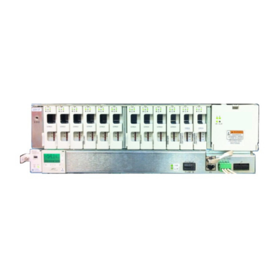
- Page 1 PRODUCT MANUAL CPS2400U Upstream System – 19” Remote Power System 48 V Input, ±190 V Output Converter/Limiter System Page 1 © Copyright 2021 ABB. All rights reserved.
- Page 2 This page intentionally left blank Page 2 © Copyright 2021 ABB. All rights reserved.
-
Page 3: Table Of Contents
Verify Normal States····································································································································· 28 Verify UL Installation Compliance ·············································································································· 28 Configure Controller ····································································································································· 28 Confirm Operation of Alarm Wiring ··········································································································· 29 Troubleshooting ······································································································································ 31 System ····························································································································································· 31 Alarm Card ······················································································································································ 33 Page 3 © Copyright 2021 ABB. All rights reserved. - Page 4 Appendix A: Operating Temperature Measurement and Vertical Spacing ·········································· 48 Appendix B: Alarm Reference Table ········································································································ 50 Appendix C: Operation without a Controller - Alarm Wiring ································································ 52 Appendix D: Installationsanleitung ······································································································· 55 Revision ··················································································································································· 56 Page 4 © Copyright 2021 ABB. All rights reserved.
-
Page 5: Table Of Figures
Figure 33 Converter Slot Fillers ·············································································································· 49 Figure 34 Office Alarm Pin Outs - Alarm Cards ····················································································· 52 Figure 35 Alarm Card Pin Out ·················································································································· 54 Figure 36 Alarm Card Cables ··················································································································· 54 Page 5 © Copyright 2021 ABB. All rights reserved. -
Page 6: Table Of Tables
Table 8 Specifications ····························································································································· 42 Table 9 Minimum feed Loop Length for 10,000 A Short Circuit Current ············································· 43 Table 10 Alarm Reference Table ·············································································································· 50 Table 11 Converter Shelf Alarm Card States ·························································································· 52 Page 6 © Copyright 2021 ABB. All rights reserved. -
Page 7: Introduction
ABB phones are staffed from 7:00 am to 5:00 pm USA Central Time Zone (GMT -6), Monday through Friday, on normal business days. At other times, this number is still available, but for emergencies only. - Page 8 This page intentionally left blank Page 8 © Copyright 2021 ABB. All rights reserved.
-
Page 9: Product Description
Product Description The CPS2400U Upstream System delivers power over telephone lines. The primary application is enabling the delivery of video bandwidth data rates to residences over twisted pairs by allowing placement of powered electronics at an acceptable distance from the residence. -
Page 10: Operation
Galaxy Protocol over an RS485 bus. Up to 24 shelves can be controlled and monitored by one system controller. The controller is WEB and SNMP capable. Page 10 © Copyright 2021 ABB. All rights reserved. -
Page 11: Configurations
Fan Shelves - 1 or 2 Baffle Converter Shelves Converter Shelf Stack 1 to 3 Primary with Controller Fan Shelves - 1 or 2 Controller in Primary Fan Shelf Figure 2 Configuration Page 11 © Copyright 2021 ABB. All rights reserved. - Page 12 This page intentionally left blank Page 12 © Copyright 2021 ABB. All rights reserved.
-
Page 13: Installation
Vertical space is permitted below Baffles for future Converter Shelf addition. Baffle may be installed 12.5 inch rack space above a Fan Shelf. • No vertical space between: Fan Shelves • Fan Shelf and Converter Shelf • Converter Shelves • Page 13 © Copyright 2021 ABB. All rights reserved. -
Page 14: Mount Shelves
Baffle –Orient to direct air in from the front (aisle) and out to the back of the rack. Mount Lowest Fan Shelf in a position allowing space above for all planned shelves. Mount the remaining shelves and baffles above the lowest shelf, working from bottom to Page 14 © Copyright 2021 ABB. All rights reserved. -
Page 15: Figure 3 Fan Shelf Mounting
Figure 4 Baffle Mounting Figure 3 Fan Shelf Mounting Figure 5 Converter Shelf Mounting Page 15 © Copyright 2021 ABB. All rights reserved. -
Page 16: Ground Converter Shelves
Ground Converter Shelves Fan shelves will be grounded when connecting input power. Step Action 6 AWG minimum Ground Lead Repeat from for remaining Converter Shelves. Connect Input Power Step Action ESD Jack Page 16 © Copyright 2021 ABB. All rights reserved. -
Page 17: Figure 8 Converter Shelf Dc Connections Access
Verify with a Volt meter. Turn OFF circuit breakers assigned to this frame and verify with an volt meter Open the distribution panel door on the right end of the shelf. Page 17 © Copyright 2021 ABB. All rights reserved. -
Page 18: Figure 9 Converter Shelf Input Power Connections
Reference NEC Table 310-16 for applications of not more than three conductors in a raceway and correction factors for Ambient Temperatures over 30°C. Each installation will vary and the installer should review NEC cabling requirements as well as local practice to ensure proper cable sizing is achieved for the local conditions. Page 18 © Copyright 2021 ABB. All rights reserved. -
Page 19: Figure 10 Fan Shelf Input Power Connections
Connect Frame Ground wire. Screws A Feed (-48V) -48V RTN B Feed (-48V) Frame Ground 24-16 gauge Figure 10 Fan Shelf Input Power Connections Repeat from Step 8 for remaining Fan Shelves. Page 19 © Copyright 2021 ABB. All rights reserved. -
Page 20: Connect Load Wiring
The wiring assignment information in Table 6 provides the appropriate connections for each circuit. Cables should be provided with this pinout configuration to terminate the J1 output connector on each Converter Shelf. Step Action • • Clip Page 20 © Copyright 2021 ABB. All rights reserved. -
Page 21: Inspect The Network
Converter Shelf to the cabinet ground bus should indicate continuity as determined vi a meter providing an audible beep or the standard method of continuity verification used in the network. Many network providers use a maximum value of 10 ohms. Page 21 © Copyright 2021 ABB. All rights reserved. -
Page 22: Install Controller
This step is shown here only for completeness. It is to be performed after the Apply DC Power section is completed. Circuit powering is usually accomplished by closing the circuit using a 5-pin protector after DC power applied to the system. Install Controller Step Action Screw Page 22 © Copyright 2021 ABB. All rights reserved. -
Page 23: Set Shelf Id
Set Shelf ID Systems Equipped With Controller - Set ID (address) of each shelf to a unique value. Systems Without Controller –ID (address) not used. Step Action Page 23 © Copyright 2021 ABB. All rights reserved. -
Page 24: Figure 16 Shelf Id Setting
2 for 12 cards per shelf. Shelf 6 Shelf 5 Shelf 4 Shelf 3 Shelf 2 Cards per Shelf 1 shelf UNIT Shelf 6 Setting Shelf 1 Setting Page 24 © Copyright 2021 ABB. All rights reserved. -
Page 25: Install Inter-Shelf Signal Cables
Shelf Stack below, if present Connect Office Alarms See Appendix C: Operation without a Controller - Alarm Wiring for systems without a controller. Step Action Controller). See footnote on page 26 Page 25 © Copyright 2021 ABB. All rights reserved. -
Page 26: Connect Local Network
RJ45 connectors of Converter Shelves are located on their Alarm Cards. Office Alarm Cable is separately ordered. For available cables see Line Power Product Line Brochure. Page 26 © Copyright 2021 ABB. All rights reserved. -
Page 27: Install Converters
Fault LEDs will flash red until communications is established between the system components. – see Verify Normal States for details. Step Action Apply DC power by turning on circuit breakers and inserting fuses feeding both Fan Shelves and the Converter Shelves. Page 27 © Copyright 2021 ABB. All rights reserved. -
Page 28: Verify Normal States
Site ID, Site Description, System Date, System Time, and Shelf J-Code or Product Code Network page (Settings tab, Communications group): DHCP Client / Fixed IP Address FTTN page (Settings tab, System group): Alarm parameters Page 28 © Copyright 2021 ABB. All rights reserved. -
Page 29: Confirm Operation Of Alarm Wiring
If a controller is installed in the system then it will indicate an alarm state by red display backlight. Using the buttons on the keypad specific alarms can be retrieved by pressing the Back Arrow, . When system returns to normal function the display will be green. Page 29 © Copyright 2021 ABB. All rights reserved. - Page 30 This page intentionally left blank Page 30 © Copyright 2021 ABB. All rights reserved.
-
Page 31: Troubleshooting
Various Green Green Equipment Yellow Yellow Green Yellow Yellow Yellow Yellow Yellow Green Fail Communication Controller. Green Fail Removed communication. Green Fail None Green Green Yellow Standby Yellow Yellow Green Yellow Page 31 © Copyright 2021 ABB. All rights reserved. - Page 32 Green Yellow Yellow Green Green Failed Yellow Green Yellow Green terminal Yellow Green Yellow Green Green Green Yellow Green Green feature. Yellow Green Green feature. Green Green measurement. Yellow Green Green Page 32 © Copyright 2021 ABB. All rights reserved.
-
Page 33: Alarm Card
Green Minor Green Minor Major Green Major Major Major Green Major Major Major Major Major Major Unpowered 5 Empty cells indicate: OK for inputs, OFF for LEDs, and non-alarm for relays. Page 33 © Copyright 2021 ABB. All rights reserved. - Page 34 -48V Input Feed Alarm State – the alarm state of the four -48V shelf feeds: - Table 2. None Minor One input feed Low Major Multiple input feeds Low See footnote on page 36 Page 34 © Copyright 2021 ABB. All rights reserved.
-
Page 35: Converter Leds
Note: Test points work best if each voltage is measured with respect to ground. Conditions Notes None Green Yellow Standby browser. Green to ground Green other voltage problem voltage Conditions None See footnote on page 36 Page 35 © Copyright 2021 ABB. All rights reserved. - Page 36 Examples in the table are shown for conditions on the B circuit of the QS982A card. The same Conditions and Actions apply for the A circuit when A circuit LEDs are illuminated. Page 36 © Copyright 2021 ABB. All rights reserved.
-
Page 37: Locating Failed Fans
See Appendix C: Operation without a Controller - Alarm Wiring for systems without a controller. Controller Office Alarm Connector is located on the front of the Primary Fan Shelf - Figure 28. Figure 26 Office Alarm Connections with Controller Page 37 © Copyright 2021 ABB. All rights reserved. -
Page 38: Figure 27 Converter Shelf Output Connector
24 AWG solid or stranded or 26 AWG solid AMP 229974-1 or equivalent. • The connector shall be arranged with a right angle housing such that the cable exits to the pin 1 side. Page 38 © Copyright 2021 ABB. All rights reserved. - Page 39 Examples in the table are shown for conditions on the B circuit of the QS982A card. The same Conditions and Actions apply for the A circuit when A circuit LEDs are illuminated. Page 39 © Copyright 2021 ABB. All rights reserved.
-
Page 40: Vertical Spacing, Airflow, Baffles, And Fan Shelves
It is designed for use with user provided vertical airflow cooling of at least 175 linear feet per minute over the entire flow cross-section of the shelf. • Equipment may be placed on top of the CPS2400U provided airflow is not impeded or sufficient spacing is provided. Outdoor Cabinet Application The Converter System is rated to work to 65°C in stacks of two shelves in outdoor cabinets without... -
Page 41: Lugs
List 405348202 YA2CL-2TC14 LCD2-14A-Q 405347683 YAV2C-L2TC14-FX LCDX2-14A-E YA2CL-2TC14-45 LCD2-14AH-Q 408210524 YAV2C-L2TC14-FX-45 LCDX2-14AH-E 405347576 YAV4C-L2TC14-FX YAV4C-L2TC14-FX-45 405347519 YAV6C-L2TC14-FX YAV6C-L2TC14-FX-45 406021626 YA8CL2TC14 YA8CL2TC14-45 These similar lugs may have different dimensions from WP-91412 lugs. Page 41 © Copyright 2021 ABB. All rights reserved. -
Page 42: Specifications
10 µs -100 1 µs -200 26.0 27.2 33.2 35.4 10,000 diss Output 95.0 97.7 1500 Physical Parameter Symbol Typical Unit Inch Component Height Width Depth Weight See footnote on page 44 Page 42 © Copyright 2021 ABB. All rights reserved. -
Page 43: Dimensions
Figure 30 Converter Shelf Dimensions 17.2 in (437 mm) 11.9 in (303 mm) 5.0 in (127 mm) 1.73 in (44 mm) Front Figure 31 Fan Shelf Dimensions See footnote on page 44 Page 43 © Copyright 2021 ABB. All rights reserved. -
Page 44: Standards Compliance
Airflow across the entire cross section of the warmest converter shelf. Loop Length is the total length of -48V and -48V Return conductors. -40°C to 55°C for 3 converter shelves and 2 Fan Trays when equipped with QS982A Converters. Page 44 © Copyright 2021 ABB. All rights reserved. -
Page 45: Safety
Provide external current limiting protection for alarm contacts. Rating 60V, 0.5A unless otherwise noted. • Use only specified fuses and circuit breakers. • Use only GMT fuses provided with safety caps. Page 45 © Copyright 2021 ABB. All rights reserved. -
Page 46: Figure 32 Design Capacitance Safety Limit
DO NOT add capacitance to the system to reach values that exceed safety limits per the following figure: 1500 10000 1000 0.01 1000 10000 Line to earth Line to line S4651A U Voltage of the RFT circuit Figure 32 Design Capacitance Safety Limit Page 46 © Copyright 2021 ABB. All rights reserved. -
Page 47: Precautions
Personnel with electronic medical devices need to be aware that proximity to DC power and distribution systems, including batteries and cables, typically found in telecommunications utility rooms, can affect medical electronic devices, such as pacemakers. Effects decrease with distance. Page 47 © Copyright 2021 ABB. All rights reserved. -
Page 48: Appendix A: Operating Temperature Measurement And Vertical Spacing
3 inch spacing application specific testing is required. Operating Temperature The CPS2400U is rated to work to 65 C in stacks of two shelves in outdoor cabinets without baffles. Note: in outdoor cabinets where the air entering the second shelf may be heated above 65°C inlet temperature, additional airflow beyond the 175 linear feet per minute is required. -
Page 49: Figure 33 Converter Slot Fillers
Figure 33 Converter Slot Fillers Page 49 © Copyright 2021 ABB. All rights reserved. -
Page 50: Appendix B: Alarm Reference Table
2 Cards Fail Green Fail communication. Green Fail Removed None Standby Green Green Yellow Yellow Yellow Green Yellow card. Yellow Yellow Yellow card. Failed Yellow Yellow Green Yellow Yellow Green Failed Green Page 50 © Copyright 2021 ABB. All rights reserved. - Page 51 State State State Yellow Green Yellow Green Fail Yellow Green Fail Yellow Green Green Green Yellow Green Green feature. remote Yellow Green Green expected. Aborted Green Green measurement. Yellow Green Green Page 51 © Copyright 2021 ABB. All rights reserved.
-
Page 52: Appendix C: Operation Without A Controller - Alarm Wiring
A9-12, and power shelf slots 1-6 (left side) and 7-12 (right side) respectively. The B bus feeds are also designated in an identical fashion. The alarm card monitors the -48v on each of these four feeds, and asserts alarms and indicators - Table 11. 7-12 7-12 Page 52 © Copyright 2021 ABB. All rights reserved. - Page 53 Alarm Card shall assert a PMJ relay and Red ALM LED. The Alarm Card shall also monitor its internal I C to RS-485 conversion processor. A failure of this processor shall constitute a PMN condition. Page 53 © Copyright 2021 ABB. All rights reserved.
-
Page 54: Figure 35 Alarm Card Pin Out
Inter-Shelf Signal Cables are only required between Fan Shelves and the adjacent Converter Shelf in systems without a Controller. Step Action instructions. Alarm Board Open on Alarm Return Open on Alarm Open on Alarm Return Open on Alarm To Office Alarm network Page 54 © Copyright 2021 ABB. All rights reserved. -
Page 55: Appendix D: Installationsanleitung
Das Gerät hat kein Brandschutzgehäuse es darf daher nur auf nicht brennbaren Untergrund aufgestellt werden. ( Beton, Metall usw.) • Beim Aufstellen des Gerätes ist darauf zu achten das alle Anforderungen gemäß EN60950 eingehalten werden. Page 55 © Copyright 2021 ABB. All rights reserved. -
Page 56: Revision
(Standards Compliance section). Added Appendix D: Update Install Inter-Shelf Signal Cables, page 20; add reference to Galaxy Pulsar Edge Quick Start Guide Minor Revisions Initial release Updated as per template 02/08/2022 Page 56 © Copyright 2021 ABB. All rights reserved. - Page 57 – in whole or in not accept any responsibility whatsoever for potential errors or parts – is forbidden without prior written consent of ABB. possible lack of information in this document. Copyright© 2021 ABB...