
Related Manuals for Sinclair SWH-200DE

Summary of Contents for Sinclair SWH-200DE
- Page 1 SERVICE AND INSTALLATION MANUAL SINCLAIR WATER HEATER SWH-200DE+SWH-35ERA2 H E A T P U M P S...
-
Page 2: Table Of Contents
Contents PRODUCT ........................... 1 1 MODELS LIST ......................... 1 2 NOMENCLATURE ........................1 2.1 Nomenclature of outdoor unit ....................... 1 2.2 Nomenclature of water tank ......................... 2 3 FUNCTION ..........................2 4 PRODUCT PARAMETERS ...................... 3 4.1 Product Parameters of Outdoor Unit ....................3 4.2 Parameters of the Water Tank ...................... - Page 3 6.3 Circuit Diagram ..........................38 7 Installation of Communication System ................38 7.1 Communication Cable Terminal Connection ..................38 7.2 Communication Cable Connection ....................39 7.3 Installation and Disassembly of Wired Controller ................39 8 Refrigerants Perfusion ......................41 8.1 Precautions on Refrigerant Leakage ....................41 8.2 Method for Calculating Incremental Refrigerant for Extended Pipe ..........
-
Page 4: Product
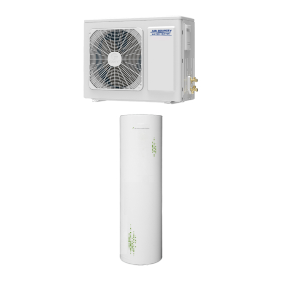
Product type Model Outline diagram capacity 3500+1500 Outdoor unit SWH-35ERA2 (electric heater) Water tank SWH-200DE 2 NOMENCLATURE 2.1 Nomenclature of outdoor unit Description Options Unit code C – Circulating; Heating style S – Static; Function character Q – Multifunctional; Single function – Omit Heating capacity 3.5kW... -
Page 5: Nomenclature Of Water Tank
SINCLAIR AIR SOURCE HEAT PUMP WATER HEATER SERVICE MANUAL 2.2 Nomenclature of water tank Description Options SWH– Water tank Water tank code Water tank material Stainless steel – Omit; T –Enameled steel Normal heat pump water tank – Omit; V – Heat pump water... -
Page 6: Product Parameters
④ Under “RAPID” function, electric heater helps to heating water. ⑤ Please always see the nameplate for the exact data as this table is subject to change. 4.2 Parameters of the Water Tank SWH-200DE Model Capacity Power Supply for Electric Heater... -
Page 7: Performance Data Of Hot Water Mode
SINCLAIR AIR SOURCE HEAT PUMP WATER HEATER SERVICE MANUAL ② Type selection of water tank shall also be made based on local climatic conditions and opinions from professionals. ③ For units with water tank equipped with an electrical heater, that is, the water tank model of which starts with SWH, both the heat pump and electrical heater are started for heat up under low ambient temperature or “RAPID”... -
Page 8: Optional Accessories
The air source heat pump water heater is a novel, efficient, energy-saving, and environment-friendly heater product. 6 Optional Accessories The Sinclair air source water heater unit supports the following accessories: Item Self-limiting temperature tracing belt Pressure stabilizing valve NOTE: If any of the preceding accessories is required, contact with the local sales company. -
Page 9: Control
SINCLAIR AIR SOURCE HEAT PUMP WATER HEATER SERVICE MANUAL CONTROL 1 Unit Control 1.1 Overall Control Logic (1) High pressure switch When the discharge pressure of compressor exceeds the preset value, an error will be displayed and the unit will stop or not start. -
Page 10: Wired Controller
SINCLAIR AIR SOURCE HEAT PUMP WATER HEATER SERVICE MANUAL (2) Control on fan motor When start up conditions of the compressor is met, the system starts by following the hot water sequence. The electronic expansion valve resets and is initialized, and the external fan motor starts. -
Page 11: Query Parameters
SINCLAIR AIR SOURCE HEAT PUMP WATER HEATER SERVICE MANUAL Display of Common Operation Modes: Display of defrost, antifreeze running, and e-heater HOTWATER, SAVE, PRESET and NIGHT running (or display of the Special E-HEATER Mode). mode. Display of hot water volume (this function is Display of RAPID and i-know function. -
Page 12: Common Modes Setting
SINCLAIR AIR SOURCE HEAT PUMP WATER HEATER SERVICE MANUAL 4.2 Common Modes Setting In the On state of the unit, press the MODE button to switch the operation modes in the following sequence: PRESET HOTWATER SAVE NIGHT The HOTWATER mode is shown in the following figure. -
Page 13: Water Temperature Setting
SINCLAIR AIR SOURCE HEAT PUMP WATER HEATER SERVICE MANUAL In the E-HEATER mode, users can press the MODE button to switch to the HOTWATER mode. Note that the E-HEATER mode will be cancelled automatically and the HOTWATER mode will be started upon restart of the water heater in the case of blackout. - Page 14 SINCLAIR AIR SOURCE HEAT PUMP WATER HEATER SERVICE MANUAL 4.5.2 Timer Setting Timer setting: Under the HOTWATER or SAVE mode or under the Off state, press the TIMER button to enter the timer setting interface. The TIMER and ON icons are on and the hour value blinks.
- Page 15 SINCLAIR AIR SOURCE HEAT PUMP WATER HEATER SERVICE MANUAL 4.5.3 Preset Time Setting In the PRESET mode, hot water is prepared in advance by the preset time. In the main interface of the PRESET mode, press the TIMER button to enter the selection interface.
-
Page 16: Function Setting
SINCLAIR AIR SOURCE HEAT PUMP WATER HEATER SERVICE MANUAL PRESET 1 or Press the PRESET 1 Press ▲ or ▼ to select Main interface PRESET 3 TIMER button. blinks. PRESET X blinks. The minute The hour value value of Press the... - Page 17 SINCLAIR AIR SOURCE HEAT PUMP WATER HEATER SERVICE MANUAL blinks. Then users can press ▲ or ▼ to start or cancel this function. If no operation is performed within 5s, it will be regarded that this function is not required. If this function is started, the function icon is displayed without blinking.
- Page 18 SINCLAIR AIR SOURCE HEAT PUMP WATER HEATER SERVICE MANUAL Circular sterilization: Sterilization is performed circularly by the d value. Once the circular sterilization conditions are met, sterilization is performed regardless of on/off status of the controller and beyond limit of common modes and functions except VACATION.
- Page 19 SINCLAIR AIR SOURCE HEAT PUMP WATER HEATER SERVICE MANUAL ④ Ensure that there is no long-term power failure; otherwise, the clock of the water heater will malfunction and the STERILIZE function will not work properly. ⑤ Under the E-HEATER mode, the STERILIZE function is unavailable.
-
Page 20: Special Function
SINCLAIR AIR SOURCE HEAT PUMP WATER HEATER SERVICE MANUAL long-term power failure; otherwise, the clock of the water heater will malfunction and the VACATION function will not work properly. 4.7 Special Function 4.7.1 Keypad Lock In normal status of the unit, press and hold ▲+▼ for 5s. The LOCK icon is displayed on the controller and all buttons become unavailable. -
Page 21: Installation
SINCLAIR AIR SOURCE HEAT PUMP WATER HEATER SERVICE MANUAL INSTALLATION 1 Engineering Installation Flowchart Figure 1-1 Flowchart for installing a split-type coil unit... -
Page 22: Preparations
2.1.2 Importance of Engineering Installation The installation process of a Sinclair air source water heater involves installation of various parts, such as that of the unit and water tank, water pipe or copper pipe between the unit and water tank, pipes between the water tank and indoor cool/hot water pipes, wired controller, power cord, and control circuit. -
Page 23: Design Drawing Review
SINCLAIR AIR SOURCE HEAT PUMP WATER HEATER SERVICE MANUAL Installation Problem Adverse Effect City water is unavailable or the water pressure The unit fails to work and complaints are generated due to is too low or too high while no remedial unavailability of hot water. -
Page 24: Installation Material Selection
SINCLAIR AIR SOURCE HEAT PUMP WATER HEATER SERVICE MANUAL Items to be checked during drawing review: Item Check Result It is recommended that the distance between the coil unit and water tank is within 10 meters. If the distance is with 3 meters, the connection pipe delivered with the unit can be used. - Page 25 SINCLAIR AIR SOURCE HEAT PUMP WATER HEATER SERVICE MANUAL (5) Specifications: Outside Diameter of Copper Pipe (mm) Refrigerant Type Minimum Wall Thickness (mm) R134a 6.35 R410A R134a 0.71 9.52 R410A R134a 12.7 R410A 2.3.2.2 Water Pipe Selection (1) Selection of PPR water pipe...
-
Page 26: Installation Of The Unit
SINCLAIR AIR SOURCE HEAT PUMP WATER HEATER SERVICE MANUAL 2.3.2.4 Selection of Communication Cable Twisted pairs or shielded twisted pairs that are already configured for the unit must be adopted as the communication cable and control cable. For standard configuration, length of the communication cable between the unit and wired controller is 8 m. - Page 27 SINCLAIR AIR SOURCE HEAT PUMP WATER HEATER SERVICE MANUAL 3.1.3 Requirements on Installation Space The distance between the outdoor unit and wall or any other obstacle must be proper, as shown in Figure 3-2. Figure 3-2 Space requirements for installation (Unit: mm) (1) If a canopy is to be installed for the water heater outdoor unit, note that the heat dissipation and absorption should not be affected.
- Page 28 SINCLAIR AIR SOURCE HEAT PUMP WATER HEATER SERVICE MANUAL (6) Build a drainage ditch around the foundation to discharge the condensate water. (7) If the outdoor unit is installed on the roof, check the intensity of the building and take waterproof measures.
-
Page 29: Installation Of Water Tank
SINCLAIR AIR SOURCE HEAT PUMP WATER HEATER SERVICE MANUAL 3.2 Installation of Water Tank 3.2.1 Overall Dimensions and Size of Installation Holes External Dimensions and Installation & Maintenance Space of SWH-200DE Parameter 2000 1797 G1/2 Cool water inlet (internal thread) -
Page 30: Refrigerant Pipe Design
Length of both pipes is 3 m. If the pipe needs to be extended, this specification needs to be followed. The Sinclair air source water heater system poses high requirements on cleanliness and dryness. Therefore, special attention must be paid when connecting the refrigerant pipe to the indoor and outdoor units. - Page 31 SINCLAIR AIR SOURCE HEAT PUMP WATER HEATER SERVICE MANUAL (4) Remove the sealing caps of the connecting pipe. Align the center of the bell mouth with the pipe joint and valve cone, and screw up the conical nut with your hand and then with a wrench, as shown in Figure 4-2.
-
Page 32: Pipes Installation And Insulation
SINCLAIR AIR SOURCE HEAT PUMP WATER HEATER SERVICE MANUAL Figure 4-3 Vacuum pump connection diagram NOTES:Refrigerant perfusion refer to section 8. 5 Pipes Installation and Insulation 5.1 Pipes Installation for the Cooling System 5.1.1 Processing to Refrigerant Pipes A 3-meter refrigerant pipe is configured for the unit for standard configuration. If the required refrigerant pipe is longer than 3 m, it needs to be processed in the steps specified below. - Page 33 SINCLAIR AIR SOURCE HEAT PUMP WATER HEATER SERVICE MANUAL (1) Requirements The radius of the bending pipe must exceed 3.5D. The ratio of the short diameter after bending to the original diameter must exceed 2/3. (2) Processing methods: Manual bending: applies to thin copper pipes (Φ6.35 mm to Φ12.7 mm) Mechanical bending: applicable range (Φ6.35 mm to Φ44.45mm)
- Page 34 SINCLAIR AIR SOURCE HEAT PUMP WATER HEATER SERVICE MANUAL 5.1.2.2 Construction of Supports, Hangers, and Brackets (1) Construction of supports, hangers, and brackets for pipes: These parts must be fixed securely in reasonable type and style without any tilt. The surface is clean without any dirt. The parts embedded into the wall or floor cannot be painted or coated and must be free from grease stains.
- Page 35 SINCLAIR AIR SOURCE HEAT PUMP WATER HEATER SERVICE MANUAL 5.1.2.4 Pipe Connection The refrigerant pipes and indoor units are connected by using the flare opening. Therefore, the quality of flaring connection must be ensured. The flaring depth of the bell mouth cannot be smaller than the caliber.
-
Page 36: Installation Of Water Pipes
SINCLAIR AIR SOURCE HEAT PUMP WATER HEATER SERVICE MANUAL 5.1.4 Vacuumization and Desiccation 5.1.4.1 Requirements on Vacuum Pump The vacuum pump for different refrigerant systems cannot be the same. The ultimate vacuum degree of the vacuum pump should reach -0.1 MPa. - Page 37 SINCLAIR AIR SOURCE HEAT PUMP WATER HEATER SERVICE MANUAL valve at the water outlet of the water tank. They must be installed if the water tank is far away (the hot water pipe is longer than 20 m) from the location for water use or all locations for water use are lower than the cold water inlet of the water tank.
-
Page 38: Thermal Insulation Measures
Don't use the accessory of any third party and replace the accessory by yourself, any losses thereof for normal operation and usage of heat pump water heater result from personal injury and improper installation,Sinclair shall not be liable. 5.3 Thermal Insulation Measures 5.3.1 Thermal Insulation for the Refrigerant Pipes... -
Page 39: Electric Installation
SINCLAIR AIR SOURCE HEAT PUMP WATER HEATER SERVICE MANUAL (7) Wrap joints of indoor/outdoor units with thermal insulation materials. There must be no gap between the joint and the wall of the indoor/outdoor unit, as shown in the following figure. -
Page 40: Installation Of Power Cord
Circuit Breaker Capacity (A) Firing Line Zero Line Ground Line 220V-240V SWH-35ERA2 ~ 50Hz 6.2.3 External Connection Diagram of the Unit The external connection diagram for equipped with SWH-200DE SWH-35ERA2 water tank is shown in the following figure. Figure 6-1 External Wiring... -
Page 41: Circuit Diagram
SINCLAIR AIR SOURCE HEAT PUMP WATER HEATER SERVICE MANUAL 6.3 Circuit Diagram unit is shown in the following figure. The circuit diagram of SWH-35ERA2 Figure 6-2 Circuit Diagram 7 Installation of Communication System 7.1 Communication Cable Terminal Connection Lead out the communication cable from the mainboard of the outdoor unit and insert it into the slot... -
Page 42: Communication Cable Connection
SINCLAIR AIR SOURCE HEAT PUMP WATER HEATER SERVICE MANUAL 7.2 Communication Cable Connection 7.2.1 Communication Cable Connection for Vertical Model The water tank does not need to communicate with the outdoor unit. Therefore, connect the communication cable led out from the outdoor unit to the wired controller. - Page 43 SINCLAIR AIR SOURCE HEAT PUMP WATER HEATER SERVICE MANUAL Figure 7-1 is the installation diagram of wired controller. Cut off power supply of heavy-current wire embedded in mounting hole in the wall before installation. The installation method is as below: Pry the removal port with straight screwdriver to separate the front panel and soleplate of wired controller;...
-
Page 44: Refrigerants Perfusion
SINCLAIR AIR SOURCE HEAT PUMP WATER HEATER SERVICE MANUAL Name Name Panel of wired controller Rubber cushion(rainproof box) Screw Rainproof box Bottom plate of wired controller Installation box inside the wall Figure 7-3 Rainproof Box Accessories of Wired Controller Figure 7-4 Disassembly Diagram of Rainproof Box of Wired Controller 8 Refrigerants Perfusion 8.1 Precautions on Refrigerant Leakage... -
Page 45: Method For Calculating Incremental Refrigerant For Extended Pipe
However, if a large amount of refrigerant leaks within a short duration, keep away from the leakage source and unplug the unit. In addition, contact the local sales company of Sinclair to handle this case onsite. 8.2 Method for Calculating Incremental Refrigerant for Extended Pipe Length of the pipe configured for the water heater for standard configuration is 3 m. -
Page 46: Check For Acceptance After Installation
SINCLAIR AIR SOURCE HEAT PUMP WATER HEATER SERVICE MANUAL replenishment (Figure 8-1 shows the diagram for refrigerant replenishment). Figure 8-1 Refrigerant replenishment diagram 9 Check for Acceptance After Installation Check Item Check Result The distance between the coil unit and water tank is smaller than 10 m. -
Page 47: Commissioning And Trial Run
SINCLAIR AIR SOURCE HEAT PUMP WATER HEATER SERVICE MANUAL COMMISSIONING and TRIAL RUN 1 Commissioning Flowchart Check before commissioning Outdoor unit Water tank Electric connection Start the unit for commissioning. Set unit parameters. Accept after commissioning. 2 Precautions on Safety... -
Page 48: Document Preparation For Commissioning
SINCLAIR AIR SOURCE HEAT PUMP WATER HEATER SERVICE MANUAL 3.2 Document Preparation for Commissioning Running Parameters for Commissioning of Household Air Source Heat Pump Water Heaters Project name: Unit model: Commissioning performed by: Water tank model: Rated capacity of the outdoor... -
Page 49: Check Before Commissioning
SINCLAIR AIR SOURCE HEAT PUMP WATER HEATER SERVICE MANUAL 3.3 Check before Commissioning 3.3.1 Selection of Installation Position 3.3.1.1 Installation Position of the Outdoor Unit (1) The outdoor unit is installed in a spacious room with good ventilation. The air inlet and outlet are not blocked. -
Page 50: Commissioning And Trial Run
SINCLAIR AIR SOURCE HEAT PUMP WATER HEATER SERVICE MANUAL 4 Commissioning and Trial Run 4.1 Precautions for Commissioning Before commissioning, ensure that the power supply model, possible usage range (pipe distance, indoor and outdoor high and low voltage difference, and power supply voltage), and installation space meet user requirements. -
Page 51: Commissioning Completed
SINCLAIR AIR SOURCE HEAT PUMP WATER HEATER SERVICE MANUAL 4.3.2 Precautions for Operation in Winter (1) Before starting the unit which has not been used for a long period or in quite low temperature in winter, energize the unit for at least 8 hours. -
Page 52: Check Before Acceptance
SINCLAIR AIR SOURCE HEAT PUMP WATER HEATER SERVICE MANUAL 5 Check Before Acceptance Checklist for Commissioning of Household Air Source Heat Pump Water Heaters Check Item Pass The heat exchange space for unit installation meets the related requirement. A drainage ditch or outlet is available near the installation position to facilitate water drainage. -
Page 53: Unit Function Setting
SINCLAIR AIR SOURCE HEAT PUMP WATER HEATER SERVICE MANUAL Running Parameters for Commissioning of Household Air Source Heat Pump Water Heaters Project name: Unit model: Commissioning performed by: Water tank model: Capacity of Rated capacity of the outdoor unit the water... -
Page 54: Maintenance
SINCLAIR AIR SOURCE HEAT PUMP WATER HEATER SERVICE MANUAL MAINTENANCE 1 Error Code Symptom Error Description The water heater stops operation and the wired controller displays E1. System high pressure protection. The water heater stops operation and the wired controller displays E3... - Page 55 SINCLAIR AIR SOURCE HEAT PUMP WATER HEATER SERVICE MANUAL Symptom Error Description The water heater stops operation and the wired controller displays LF Power protection of inverter compressor Detection circuit malfunction of driven circuit of The water heater stops operation and the wired controller displays Pc...
-
Page 56: Troubleshooting
SINCLAIR AIR SOURCE HEAT PUMP WATER HEATER SERVICE MANUAL Symptom Error Description High temperature protection of driven module of The water heater stops operation and the wired controller displays A8 inverter outdoor fan Malfunction of temperature sensor of driven The water heater stops operation and the wired controller displays A9... -
Page 57: E3 Refrigerant-Lacking Protection
SINCLAIR AIR SOURCE HEAT PUMP WATER HEATER SERVICE MANUAL Troubleshooting: 2.2 E3 Refrigerant-lacking Protection Error code: Applicable model: HOTWATER; SAVE; PRESET; NIGHT Error judgment condition and method: E3 is displayed on the wired controller. The troubleshooting method is shown in the flowchart below. -
Page 58: E4 High Discharge Temperature Protection
SINCLAIR AIR SOURCE HEAT PUMP WATER HEATER SERVICE MANUAL Troubleshooting: 2.3 E4 High Discharge Temperature Protection Error code: Applicable model: HOTWATER; SAVE; PRESET; NIGHT Error judgment condition and method: E4 is displayed on the wired controller. The troubleshooting method is shown in the flowchart below. -
Page 59: F3, F4, F6, Fd, Fe, Fl Temperature Sensor Error
SINCLAIR AIR SOURCE HEAT PUMP WATER HEATER SERVICE MANUAL Possible cause: (1) Incorrect connection of the communication cord; (2) Display board error; (3) Main board error Troubleshooting: 2.5 F3, F4, F6, Fd, FE, FL Temperature sensor Error Fault error: F3, F4, F6, Fd, FE, or FL (one or more of these codes may be displayed), for example,... -
Page 60: Repair Of Key Components
SINCLAIR AIR SOURCE HEAT PUMP WATER HEATER SERVICE MANUAL Troubleshooting: 3 Repair of Key Components 3.1 Introduction to Key Components Driven by the electric energy, the compressor compresses refrigerant to high-temperature and high-pressure gas and enables the gas to flow circularly in the refrigerant. -
Page 61: Disassembly Of Key Components
SINCLAIR AIR SOURCE HEAT PUMP WATER HEATER SERVICE MANUAL The four-way valve changes flow direction of refrigerant during defrosting of the circular water heater. In the defrosting mode, the compressed refrigerant enters the evaporator for heat exchange and defrosting after its flow direction is changed by the four-way valve. Then it flows into the tube heat changer through the expansion valve. - Page 62 SINCLAIR AIR SOURCE HEAT PUMP WATER HEATER SERVICE MANUAL (2) Disassembly of Four-Way Valve Disassembly of Four-Way Valve Procedure Description ● Record direction of the four-way valve before disconnecting it as the direction for two systems of a dual-system unit may differ.
- Page 63 SINCLAIR AIR SOURCE HEAT PUMP WATER HEATER SERVICE MANUAL To improve durability of the water tank, a magnesium stick is installed inside the water tank. Generally, the magnesium stick has a lifespan of two to three years. However, if the quality of water used by the water heater is poor, the Mg-Stick lifespan will be shortened.
-
Page 64: Exploded View And Parts List
SINCLAIR AIR SOURCE HEAT PUMP WATER HEATER SERVICE MANUAL 4 Exploded View and Parts List 4.1 Exploded View and Parts List of the Outdoor Unit Model: SWH-35ERA2 Exploded Views and spare parts list: SWH-35ERA2 SWH-35ERA2 Name of Part Part Code... -
Page 65: Exploded View And Parts List Of The Water Tank
Filter 07412802 Front Grill 39008000149 Above data is subject to change without notice, please reference the SP in global service website. 4.2 Exploded View and Parts List of the Water Tank Model: SWH-200DE Exploded Views and spare parts list:... - Page 66 SINCLAIR AIR SOURCE HEAT PUMP WATER HEATER SERVICE MANUAL Components List SWH-200DE Name of Part Part Code Quantity 05332800002 Drainage Pipe(Rubber) Safety Valve 07382801 035033000012 Water Pipe Connector Water Tank Bottom Feet 26902848 Electric Heater 32112800004 Temperature Sensor 39000106003101 100002060368...
-
Page 67: Unit Maintenance
SINCLAIR AIR SOURCE HEAT PUMP WATER HEATER SERVICE MANUAL UNIT MAINTENANCE 1 Water Input and Drainage of Water Tank (1) Operation process for water input on the water tank 1) Cut off the power supply and open the cut-off valve at the water inlet of the tap faucet. -
Page 68: Maintenance Of The Unit
SINCLAIR AIR SOURCE HEAT PUMP WATER HEATER SERVICE MANUAL case, a stabilizing valve needs to be added to the tap water replenishment pipe to reduce water replenishment pressure. Open the safety valve’s handle to check whether it is blocked on a regular (about once a month) basis. - Page 69 SINCLAIR AIR SOURCE HEAT PUMP WATER HEATER SERVICE MANUAL Temperature Resistance Temperature Resistance Temperature Resistance (°C) (kΩ) (°C) (kΩ) (°C) (kΩ) 32.94 2.702 0.456 31.38 2.611 0.444 29.9 2.523 0.433 28.51 2.439 0.422 27.18 2.358 0.412 25.92 2.28 0.401 24.73 2.205...
- Page 70 SINCLAIR AIR SOURCE HEAT PUMP WATER HEATER SERVICE MANUAL Table 5-2 Mapping between the temperature and resistance of 20 kΩ (tube sensor and gas suction temperature sensor) Temperature Resistance Temperature Resistance Temperature Resistance (°C) (kΩ) (°C) (kΩ) (°C) (kΩ) 361.8 39.87...
- Page 71 SINCLAIR AIR SOURCE HEAT PUMP WATER HEATER SERVICE MANUAL Table 5-3 Mapping between the temperature and resistance of 50 kΩ (upper and lower temperature sensors in the water tank and gas discharge temperature sensor) Temperature Resistance Temperature Resistance Temperature Resistance (kΩ) (°C)
- Page 72 AIR SOURCE HEAT PUMP WATER HEATER SERVICE MANUAL SINCLAIR Temperature Resistance Temperature Resistance Temperature Resistance (kΩ) (°C) (kΩ) (°C) (kΩ) (°C) 84.956 7.7257 1.3803 81.052 7.4702 1.3474 77.349 7.2245 1.3155 73.896 6.9882 1.2846 70.503 6.7608 1.2545 67.338 6.542 1.2233 64.333 6.3315...
- Page 74 London W1F 7LD Great Britain www.sinclair-world.com This product was manufactured in China (Made in China). REPRESENTATIVE, TECHNICAL SUPPORT Sinclair Global Group spol. s r.o. Purkyňova 45 612 00 Brno Czech republic Tel.: +420 541 590 140 Fax: +420 541 590 124 www.sinclair-solutions.com...