
Related Manuals for Planet IGS-504HPT


Summary of Contents for Planet IGS-504HPT
- Page 1 Industrial 4-Port 10/100/1000BASE-T 802.3at PoE+ Switch IGS-504HPT/IGS-614HPT User’s Manual...
-
Page 2: Table Of Contents
Table of Contents 1. Packet Contents ................... 3 2. Product Specifications ................4 3. Hardware Introduction ................6 3.1 Switch Front Panel ................. 6 3.2 LED Indicators ................7 3.3 Switch Upper Panel ................ 8 3.4 Wiring the Power Inputs ..............9 3.5 Wiring the Fault Alarm Contact ............. -
Page 3: Packet Contents
1. Packet Contents Thank you for purchasing PLANET IGS-504HPT/IGS-614HPT Industrial 5-/6- Port Gigabit Ethernet Switch with 4-Port PoE+. The interfaces of these models are shown below: Model Name 10/100/1000T RJ45 Port 100/1000X SFP Slot PoE+ Port IGS-504HPT IGS-614HPT In the following section, the term “Industrial PoE+ Switch” means the IGS-504HPT/IGS-614HPT. -
Page 4: Product Specifications
2. Product Specifications Model IGS-504HPT IGS-614HPT Hardware Specifications 5 10/100/100/1000BASE-T RJ45 auto-MDI/MDI-X Copper Ports ports Four ports with 802.3at PoE+ injector function PoE Injector Ports (Port 1 to Port 4) DC12V: 60W PoE Budget DC24V: 90W DC48V~54V: 120W 1 1000BASE-SX/LX/BX SFP interface SFP Slots... - Page 5 Switch Specifications Switch Architecture Store-and-Forward Switch Fabric 10Gbps 12Gbps Throughput 7.4Mpps@64bytes 8.93Mpps@64bytes (packet per second) Address Table 2K entries Buffer Memory 4M bits on-chip buffer memory Jumbo Frame 9Kbytes Back pressure for half duplex Flow Control IEEE 802.3x pause frame for full duplex Standards Conformance Regulatory Compliance FCC Part 15 Class A, CE IEC 60068-2-32 (free fall) Stability Testing...
-
Page 6: Hardware Introduction
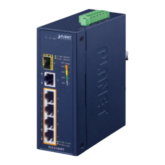
LNK/ACT PoE-in-Use PoE-in-Use IGS-504HPT IGS-614HPT Figure 3-1: IGS-504HPT Front View Figure 3-2: IGS-614HPT Front View 1. Gigabit Ethernet TP Interfaces 10/100/1000BASE-T copper, RJ45 twisted-pair: Up to 100 meters. 2. 100/1000BASE-X SFP Slot (IGS-614HPT) The SFP slot built in the IGS-614HPT supports SFP auto-detection and dual speed as it features 1000BASE-SX/LX/BX and 100BASE-FX SFP (small form-factor pluggable) fiber-optic modules. The distance can... -
Page 7: Led Indicators
3.2 LED Indicators System Color Function Green Lights to indicate power 1 has power. Green Lights to indicate power 2 has power. Alarm Lights to indicate either power 1 or power 2 has no power. PoE Power Usage (Unit: Watt) Color Function Off to indicate the PoE usage is less than 14W. -
Page 8: Switch Upper Panel
Per 10/100/1000BASE-T Interface (Port 5) Color Function Lights to indicate the port is successfully established at 1000Mbps. 1000 Green LNK/ACT Blinks to indicate that the Switch is actively sending or receiving data over that port. Lights to indicate the port is successfully established at 100Mbps or 10Mbps. -
Page 9: Wiring The Power Inputs
3.4 Wiring the Power Inputs The 6-contact terminal block connector on the top panel of Industrial PoE+ Switch is used for two DC redundant power inputs. Please follow the steps below to insert the power wire. When performing any of the procedures like inserting the wires or tightening the wire-clamp screws, make sure the power is OFF to prevent from getting an electric shock. -
Page 10: Wiring The Fault Alarm Contact
2. Tighten the wire-clamp screws for preventing the wires from loosening. Power 1 Alarm Power 2 The wire gauge for the terminal block should be in the range between 12 and 24 AWG. 3.5 Wiring the Fault Alarm Contact The fault alarm contacts are in the middle of the terminal block connector as the picture shows below. -
Page 11: Grounding The Device
1. The wire gauge for the terminal block should be in the range between 12 and 24 AWG. 2. Alarm relay circuit accepts up to 24V, max. 1A currents. 3.6 Grounding the Device Uses MUST complete grounding wired with the device; otherwise, a sudden lightning could cause fatal damage to the device. -
Page 12: Installation
Please read this chapter completely before continuing. This following pictures show how to install the device. However, the device in the picture is not IGS-504HPT nor IGS-614HPT. 4.1 DIN-rail Mounting Installation 4.2 Wall-mount Plate Mounting... -
Page 13: Side Wall-Mount Plate Mounting
4.3 Side Wall-mount Plate Mounting You must use the screws supplied with the wall-mounting brackets. Damage caused to the parts by using incorrect screws would invalidate your warranty. -
Page 14: Customer Support
Customer Support Thank you for purchasing PLANET products. You can browse our online FAQ resource at the PLANET Web site first to check if it could solve your issue. If you need more support information, please contact PLANET support team. - Page 15 FCC Warning This device has been tested and found to comply with the limits for a Class A digital device, pursuant to Part 15 of the FCC Rules. These limits are designed to provide reasonable protection against harmful interference when the equipment is operated in a commercial environment.