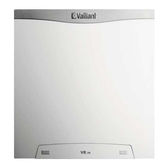
Vaillant VR 70 Installation Instructions Manual
Wiring centre
Hide thumbs
Also See for VR 70:
- Installation instructions manual (12 pages) ,
- Schematics and installation manual (44 pages)
Table of Contents
Advertisement
Quick Links
Advertisement
Table of Contents

Summary of Contents for Vaillant VR 70
- Page 1 Wiring centre VR 70 en Installation instructions...
-
Page 2: Table Of Contents
Installation instructions Contents Safety ..............3 Action-related warnings ......... 3 Intended use ............3 General safety information ........3 Regulations (directives, laws, standards) ....4 Notes on the documentation ......5 Observing other applicable documents ....5 Storing documents..........5 Validity of the instructions ........ -
Page 3: Safety
not be carried out by children unless they are Safety supervised. Action-related warnings Intended use also covers installation in ac- Classification of action-related warnings cordance with the IP code. The action-related warnings are classified in Any other use that is not specified in these accordance with the severity of the possible instructions, or use beyond that specified in danger using the following warning symbols... -
Page 4: Regulations (Directives, Laws, Standards)
▶ Secure all connection cables in the hous- ing using the enclosed strain relief. ▶ Do not use the unit's free terminals as sup- ports for other wiring. 1.3.4 Risk of material damage caused by using an unsuitable tool ▶ Use the correct tool. Regulations (directives, laws, standards) ▶... -
Page 5: Notes On The Documentation
VR 70 Product designation Operating voltage Validity of the instructions Power consumption These instructions apply only to: Switching capacity for each VR 70 – article number relay and overall switching capacity Great Britain 0020184844 CE marking Product description ... -
Page 6: Removing The Front Casing
Removing the front casing Installing the front casing Mount the front casing at the top of the wall socket. Use the fixing screw to secure the front casing. Slide the cover over the fixing screw until the cover clicks into place. Electrical installation Only qualified electricians may carry out the electrical install- ation. -
Page 7: Setting The Bus Address
Connect the eBUS line to the terminal block on the PCB. In doing so, ensure that you comply with the po- larity in the system. Address switch ▶ Assign a unique address to each VR 70 that is connec- ted, beginning with Address 1. 0020198787_01 Installation instructions... -
Page 8: Decommissioning
For contact details for our customer service department, you can write to the address that is provided on the back page, ▶ Decommission all system components of the heating or you can visit www.vaillant.co.uk. installation, as described in the installation instructions for the individual system components. Technical data 6.1.1... - Page 12 Supplier Vaillant Ltd. Nottingham Road Belper Derbyshire DE56 1JT Telephone 0330 100 3143 info@vaillant.co.uk www.vaillant.co.uk 0020198787_01 Publisher/manufacturer Vaillant GmbH Berghauser Str. 40 D-42859 Remscheid Tel. +49 2191 18 0 Fax +49 2191 18 2810 info@vaillant.de www.vaillant.de © These instructions, or parts thereof, are protected by copyright and may be reproduced or distributed only with the manufacturer's written consent.


