Vaillant VRC 700 Schematics And Installation Manual
Hide thumbs
Also See for VRC 700:
- Schematics and installation manual (44 pages) ,
- System installation instructions (80 pages) ,
- Operating instructions manual (28 pages)
Table of Contents
Advertisement
Quick Links
- 1 Schematic Diagrams
- 2 Combination Boiler, 1 Radiator Zone
- 3 System Boiler, Domestic Hot Water, 1 Radiator Zone
- 4 System Boiler, Domestic Hot Water, 1 Radiator Zone, 1 Underfloor Zone
- 5 Vrc 700 Commissioning / Configuration
- 6 Vrc700 System Configuration Relevant Settings
- 7 Schematics Legend
- Download this manual
UK VRC 700(f) Boiler Schematics
and Installation Guide
Controls: VRC700(f), VR91(f), VR70, VR71
This guide booklet contains information to assist in the installation and commissioning
of your boiler system. This booklet should be used alongside all the relevant manuals for
the equipment supplied.
Please read the contents very carefully for a successful installation.
Table of Contents
General Notes .................................................................................................................................................. 2
Terms and Conditions for Vaillant Schematic Diagrams ................................................................................... 2
Schematic Diagrams......................................................................................................................................... 3
VRC 700 Commissioning / Configuration ........................................................................................................ 29
VRC700 System Configuration Relevant Settings ........................................................................................... 32
Schematics Legend......................................................................................................................................... 39
Advertisement
Table of Contents

Related Manuals for Vaillant VRC 700


Summary of Contents for Vaillant VRC 700
-
Page 1: Table Of Contents
Please read the contents very carefully for a successful installation. Table of Contents General Notes ..............................2 Terms and Conditions for Vaillant Schematic Diagrams ................... 2 Schematic Diagrams............................3 VRC 700 Commissioning / Configuration ......................29 VRC700 System Configuration Relevant Settings ................... 32... -
Page 2: General Notes
• In no circumstances shall Vaillant be liable to you or any other third parties for any loss or damage (including, without limitation, damage for loss of business or loss of profits) arising directly or indirectly from your use of or inability to use, this diagram. -
Page 3: Schematic Diagrams
Schematic Diagrams The below systems are the most popular system installations in the UK. For further assistance please call Vaillant Technical on: 0344 693 3133 For the relevant settings in the VRC700 wired or wireless controller, refer to page 32. -
Page 4: Combination Boiler, 1 Radiator Zone
Drg. No. 23 – Combination Boiler, 1 Radiator Zone For VRC700 System Configuration Relevant Settings see page 32... -
Page 6: Combination Boiler, 2 Radiator Zones
Drg. No. 91 – Combination Boiler, 2 Radiator Zones For VRC700 System Configuration Relevant Settings see page 32... -
Page 8: Combination Boiler, 3 Radiator Zones
Drg. No. 186 – Combination Boiler, 3 Radiator Zones For VRC700 System Configuration Relevant Settings see page 32... -
Page 10: Combination Boiler, 1 Radiator & 1 Underfloor Zone
Drg. No. 159 – Combination Boiler, 1 Radiator & 1 Underfloor Zone For VRC700 System Configuration Relevant Settings see page 32... -
Page 12: Combination Boiler, 2 Radiator & 1 Underfloor Zone
Drg. No. 90 – Combination Boiler, 2 Radiator & 1 Underfloor Zone For VRC700 System Configuration Relevant Settings see page 32... -
Page 14: System Boiler, Domestic Hot Water, 1 Radiator Zone
Drg. No. 25 – System Boiler, Domestic Hot Water, 1 Radiator Zone For VRC700 System Configuration Relevant Settings see page 32... -
Page 16: Regular Boiler, Solar Thermal Domestic Hot Water, 1 Radiator Zone
Drg. No. 26 – Regular Boiler, Solar Thermal Domestic Hot Water, 1 Radiator Zone For VRC700 System Configuration Relevant Settings see page 32... -
Page 18: System Boiler, Domestic Hot Water, 1 Underfloor Zone
Drg. No. 59 – System Boiler, Domestic Hot Water, 1 Underfloor Zone For VRC700 System Configuration Relevant Settings see page 32... -
Page 20: System Boiler, Domestic Hot Water, 2 Radiator Zones
Drg. No. 93 – System Boiler, Domestic Hot Water, 2 Radiator Zones For VRC700 System Configuration Relevant Settings see page 32... -
Page 22: System Boiler, Domestic Hot Water, 1 Radiator Zone, 1 Underfloor Zone
Drg. No. 161 – System Boiler, Domestic Hot Water, 1 Radiator Zone, 1 Underfloor Zone For VRC700 System Configuration Relevant Settings see page 32... -
Page 24: System Boiler, Domestic Hot Water, 2 Radiator Zones, 1 Underfloor Zone
Drg. No. 124 – System Boiler, Domestic Hot Water, 2 Radiator Zones, 1 Underfloor Zone For VRC700 System Configuration Relevant Settings see page 32... -
Page 26: System Boiler, Domestic Hot Water, 3 Radiator Zones
Drg. No. 66 – System Boiler, Domestic Hot Water, 3 Radiator Zones For VRC700 System Configuration Relevant Settings see page 32... -
Page 28: System Boiler Cascade X7 Arrangement
Drg. No. 218 – System Boiler Cascade x7 Arrangement... -
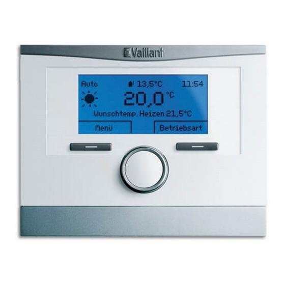
Page 29: Vrc 700 Commissioning / Configuration
VRC 700 Commissioning / Configuration When the VRC 700 is powered up for the first time, the start up assistance will guide you through several basic settings. VRC 700/5 & VRC 700f Use the rotary knob to scroll through the different language options and then press ‘OK’... - Page 30 VRC 700/4 & Earlier Models Use the rotary knob to scroll through the different language options and then press ‘OK’...
- Page 31 Scroll through and select the system diagram number applicable to the system installed. Refer to page 32 for relevant system configuration settings in accordance to the schematic drawing of the system installed. If applicable, select the configuration number. Refer to page 32 for relevant system configuration settings in accordance to the schematic drawing of the system installed.
-
Page 32: Vrc700 System Configuration Relevant Settings
The default code is ‘000’. Select ‘System configuration’. For the relevant settings in the VRC700 controller, refer to page 32. Care must be taken going through each setting diligently and adjust as necessary in accordance to system configuration and property requirements. Only key settings are listed in this document, refer to the VRC700 installation manual for further guidance. -
Page 39: Schematics Legend
Wiring Centre (VR 70) Legionella Protection Pump Zone Controller - Wireless (VR 91f) Zone Controller (VR 91) System Controller - Wireless (VRC 700f) System Controller (VRC 700) Wireless Reciever Outdoor Temperature Sensor High Limit Thermostat Immersion Heater Solar Pump Station... - Page 40 Telephone: 0330 100 3540 Sales Enquiries Technical Enquiries For installers wishing to purchase For technical assistance: Vaillant products, this is possible Telephone: 0344 693 3133 over the counter or as a next day Email: technical@vaillant.co.uk service at most plumbing and...