Table of Contents
Advertisement
Quick Links
TRUE
food service equipment
CONGRATULATIONS!
You have just purchased the finest commercial refrigerator
available. You can expect many years of trouble-free operation.
TABLE OF CONTENTS
MAINTENANCE, CARE, CLEANING
Cleaning Condenser Coil
WARRANTY
Warranty
TRUE FOOD SERVICE EQUIPMENT, INC.
2001 East Terra Lane • O'Fallon, Missouri 63366-4434
(636)-240-2400 • FAX (636)-272-2408 • INT'L FAX (636)272-7546 • (800)-325-6152
Parts Department (800)-424-TRUE • Parts Department FAX# (636)-272-9471
Web: www.truemfg.com
,
.
inc
1
2
3
4
5
5
6
7
9
10
14
25
25
26
27
29
refrigerated food prep
INSTALLATION MANUAL
refrigerated food prep
UNDERCOUNTERS
WORKTOPS
SANDWICH/SALAD
PIZZA PREP &
FOOD PREP
TWT-67D-2
TPP-67
TSSU-48-10
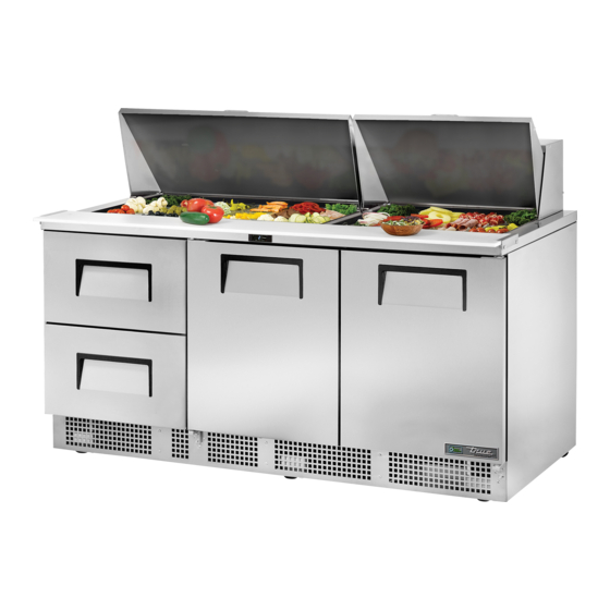
TFP-72-30M-D-2
INSTALLATION MANUAL
Advertisement
Table of Contents

Related Manuals for True TFP-72-30M-D-2


Summary of Contents for True TFP-72-30M-D-2
-
Page 1: Table Of Contents
Warranty TFP-72-30M-D-2 INSTALLATION MANUAL refrigerated food prep TRUE FOOD SERVICE EQUIPMENT, INC. 2001 East Terra Lane • O’Fallon, Missouri 63366-4434 (636)-240-2400 • FAX (636)-272-2408 • INT'L FAX (636)272-7546 • (800)-325-6152 Parts Department (800)-424-TRUE • Parts Department FAX# (636)-272-9471 Web: www.truemfg.com... -
Page 2: Safety Information
You have selected one of the finest commercial refrigeration units made. It is manufactured under strict quality controls with only the best quality materials available. Your TRUE cooler when properly maintained will give you many years of trouble-free service. WARNING: Use this appliance for its intended purpose as described in this Owner Manual. -
Page 3: Proper Disposal, Connecting Electricity, & Adapter Plugs
NEMA plugs TRUE uses these types of plugs. If you do not have the right outlet have a certified electrician install the correct power source. NOTE: International plug configurations vary by voltage and country. -
Page 4: Installation
• Lamps must be replaced by identical lamps only. Before you start to install your TRUE unit, carefully inspect it for freight damage. If damage is discovered, immediately file a claim with • Appliance tested according to the climate classes 5 and 7 the delivery freight carrier. -
Page 5: Wire Gauge Chart
38°C+), you may want to install an exhaust fan. WARNING: WARRANTY IS VOID IF VENTILATION IS INSUFFICIENT. Proper leveling of your TRUE cooler is critical to operating success (for non-mobile models). Effective condensate removal and door operation will be effected by leveling. -
Page 6: Locating And Leveling
TRUE refrigerated prep truemfg INSTALLATION OF CASTORS OR OPTIONAL LEGS Important Safeguard for installation of leg/castor. Images 1-5 demon- strate procedure. SECURING CASTORS AND LEGS To obtain maximum strength and stability of the unit, it is important that you make sure each castor is secure. Optional legs are hand- tightened securely against the lower rail assembly see image 4-5. -
Page 7: Sealing Cabinet To The Floor
TRUE refrigerated prep truemfg INSTALLATION OF CASTORS OR OPTIONAL LEGS SEALING CABINET TO FLOOR (TFP MODELS ONLY) STEP 1 - Position Cabinet - Allow one inch between the wall and ADJUSTING CASTORS FOR PROPER LEVELING rear of the refrigerator to assure proper ventilation. For freezers 3 inches between the wall and rear of the cabinet will assure proper Level unit. -
Page 8: Setup
TRUE refrigerated prep truemfg SETUP STANDARD ACCESSORIES SHELF INSTALLATION: For Proper Shelf Clip Installation Please Read The Following SHELVING INSTALLATION / OPERATION Instructions. SHELF INSTALLATION: STEP 1 A. Hook shelf clips onto shelf standards. Install the top tab of the shelf clip into the proper hole. Push up on Position all four shelf clips equal in distance from the floor for the bottom of the clip. - Page 9 TRUE refrigerated prep truemfg DRAWER REMOVAL & INSTALLATION AIR-FLOW THROUGHOUT CABINET (TPP Models Only) Depending on the version and model of the cabinet, one of the fol- WARNING: Removal of baffles in condiment pan area will adverse- lowing drawer configurations will be standard.
-
Page 10: Operation
RECOMMENDATION - Before loading product we recommend • Electronic temperature control is located on rear of unit or you run your TRUE unit empty for two to three days. This allows you behind access grill. to be sure electrical wiring and installation are correct and no ship- ping damage has occurred. -
Page 11: Mechanical Temperature Controls Sequence Of Operation
TRUE refrigerated prep truemfg MECHANICAL TEMPERATURE CONTROLS COIL SENSING An evaporator coil sensing temperature control ensures that the evaporator coil will remain clear of frost and ice by not allowing the compressor to restart until the coil temperature is above the freezing temperature. - Page 12 TRUE refrigerated prep truemfg WHEN TO MAKE AN ADJUSTMENT TO A MECHANICAL TEMPERATURE CONTROL We advise to make a mechanical temperature control adjustment only for a high altitude location. HOW TO ADJUST A MECHANICAL TEMPERATURE CONTROL OPERATION INSTRUCTIONS: Scale Guide for Measuring...
- Page 13 TRUE refrigerated prep truemfg INSTRUCTIONS: DANFOSS TEMPERATURE CONTROL ADJUSTMENT FOR HIGH ALTITUDE APPLICATIONS STEP 1 - Unplug cooler. STEP 2 - Remove the screws that secure the temperature control to the inset box. STEP 3 - To make these adjustments it may be necessary to remove the temperature control from the housing.
- Page 14 TRUE refrigerated prep truemfg CHART CCW Adjustment (based on 360°/ Height complete turn) 2000' 42° 3000' 78° 4000' 114° 5000' 150° 6000' 186° 7000' 222° 8000' 258° 9000' 294° 10,000' 330° BUL. NO.
-
Page 15: Electronic Temperature Controls Sequence Of Operation
TRUE refrigerated prep truemfg ELECTRONIC TEMPERATURE CONTROLS LAE ELECTRONIC TEMPERATURE CONTROL GENERAL SEQUENCE OF OPERATION t1 = supply air / return air* (thermostat) * STA, STG, STM, STR Models. t2 = coil / copper line (defrost) t3 = return air / supply air* (display) t3 probe is not installed and / or activated in all applications with t3 is not installed and / or activated, the display probe is t1. - Page 16 TRUE refrigerated prep truemfg HOW TO DIAGNOSE AN LAE ELECTRONIC CONTROL Indicator lights for Refrigeration/Heating Mode, Fan Operation, Defrost Mode. LAE Control LAE Control Icons Compressor Running Evaporator Fan Running Cabinet in Defrost Activation of 2nd Parameter Set Alarm Info / Set Point...
- Page 17 TRUE refrigerated prep truemfg LAE Control Info / Set Point Manual Defrost / Button Down Button Manual Activation Stand-By Up Button Button HOW TO TURN OFF THE LAE ELECTRONIC CONTROL: May need to unlock control. WHY: Turning off the control will deactivate all electrical components.
- Page 18 TRUE refrigerated prep truemfg LAE Control Info / Set Point Manual Defrost / Button Down Button Manual Activation Stand-By Up Button Button CHANGING THE "SET POINT": May need to unlock control. WHY: The set point is the temperature at which the compressor will shut off.
- Page 19 TRUE refrigerated prep truemfg LAE Control Info / Set Point Manual Defrost / Button Down Button Manual Activation Stand-By Up Button Button INITIATE A MANUAL DEFROST: May need to unlock control. WHY: A one time additional defrost may be necessary to clear accumulated frost / ice from evaporator coil.
- Page 20 TRUE refrigerated prep truemfg LAE Control Info / Set Point Manual Defrost / Button Down Button Manual Activation Stand-By Up Button Button CHANGING “DEFROST INTERVALS”: May need to unlock control. This can only be changed if defrost mode parameter “DFM” is set for “TIM”.
- Page 21 TRUE refrigerated prep truemfg LAE Control Info / Set Point Manual Defrost / Button Down Button Manual Activation Stand-By Up Button Button HOW TO CHANGE DISPLAY READOUT FROM FAHRENHEIT TO CELSIUS: May need to unlock control. This can only be changed with the LAE model BR1 version of the control.
- Page 22 TRUE refrigerated prep truemfg LAE Control Info / Set Point Manual Defrost / Button Down Button Manual Activation Stand-By Up Button Button DISPLAYING TEMPERATURE PROBES, T1, T2, T3: WHY: To display temperature probe readings in different locations of the cabinet.
- Page 23 TRUE refrigerated prep truemfg LAE Controller Parameter Settings for Celsius BIT25 For every model / version of the LAE controller, (X-32) / 1.8 ALL parameters with a formula shown need to be (X-32) / 1.8 (X-32) / 1.8 (X-32) / 1.8 converted for Celsius applications.
- Page 24 TRUE refrigerated prep truemfg DANFOSS ELECTRONIC TEMPERATURE CONTROL GENERAL SEQUENCE OF OPERATION control probe = return air defrost probe = coil DANFOSS ELECTRONIC CONTROL REFRIGERATOR WITH DIGITAL DISPLAY GENERAL SEQUENCE OF OPERATION 1. Cabinet is plugged in. a. Interior lights will illuminate on glass door models only. If the lights do not come on verify the light switch is in the “ON”...
- Page 25 TRUE refrigerated prep truemfg DANFOSS ELECTRONIC CONTROL REFRIGERATOR WITHOUT DIGITAL DISPLAY GENERAL SEQUENCE OF OPERATION 1. Cabinet is plugged in. a. Interior lights will illuminate on glass door models only. If the lights do not come on verify the light switch is in the “ON”...
-
Page 26: Important Warranty Information
When finished be sure to replace the louvered grill. The grill protects the condenser. Reconnect the electrical power to the unit. If you have any questions, please call TRUE Manufacturing at 636- 240-2400 or 800-325-6152 and ask for the Service Department. Direct to Service Department 1(855)372-1368. Service Department Availability Monday-Thursday 7:00 a.m. -
Page 27: Stainless Steel Equipment Care And Cleaning
TRUE refrigerated prep truemfg STAINLESS STEEL EQUIPMENT CARE 8 STEPS THAT CAN HELP PREVENT RUST ON AND CLEANING STAINLESS STEEL: CAUTION: Do not use any steel wool, abrasive or chlorine based USING THE CORRECT CLEANING TOOLS products to clean stainless steel surfaces. -
Page 28: General Maintenance
TRUE refrigerated prep truemfg GENERAL MAINTENANCE COMPOSITE CUTTING BOARD MAINTENANCE Please see comments from Supplier regarding composite cutting PERIODIC MAINTENANCE FOR LIDS boards below. NOTE: Because lid pin screws are designed to be removable for NOTE: Composite Cutting Boards Manufactured From Richlite cleaning, it is important these are checked periodically to assure they Material and Warping. - Page 29 TRUE refrigerated prep truemfg CHILLER HOSE (TSSU-27-12M-C MODELS ONLY) KIT CONTENTS • Hose Cleaning Brush TOOLS REQUIRED • Slotted Screwdriver • Needle Nose Pliers • Hex-Head Nut Driver WARNING: POWER MUST BE DISCONNECTED BEFORE BEGINNING THIS PROCEDURE. A. Remove the condiment pans. (Fig, 1) Remove the shelving from the unit.
- Page 30 WARRANTY CLAIMS All claims for labor or parts must be made directly through TRUE. All claims should include: model number of the unit, the serial number of the cabinet, proof of purchase, date of instal- lation, and all pertinent information supporting the existence of the alleged defect.