
Related Manuals for Viking VGIC5362


Summary of Contents for Viking VGIC5362
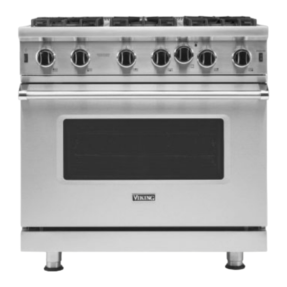
- Page 1 Installation GUIDE Professional Freestanding Open Burner Gas Ranges VGIC5302 VGIC5362 VGIC5482...
-
Page 2: Table Of Contents
Table of Contents Warnings & Important Safety Instructions ..................................3 Dimensions .............................................4 Specifi cations ............................................5 Clearance Dimensions (Proximity to Cabinets) .................................6 Clearance Dimensions (Wood/Composite Overlay) ..............................7 Electrical & Gas Requirements ......................................8 General Information ..........................................9 Installation ..............................................10 Door Removal ........................................10 Leg Installation .........................................10 Leveling/Adjustments/Alignment ................................11 Anti-tip Device Installation Wall Mount .......................................12... -
Page 3: Warnings & Important Safety Instructions
• The required use of a GFI is normally related to the location of a receptacle with respect to any signifi cant sources of water or moisture. • Viking Range, LLC will NOT warranty any problems resulting from GFI outlets which are not installed properly or do not meet the requirements below. -
Page 4: Dimensions
Dimensions 30” AND 36” W. RANGES 48” W. RANGES - 7 / ( 9 1 8 ” - 7 / ( 1 2 . 1 c 8 ” 1 . 6 - 7 / ( 7 5 8 ” . 9 c 1 ”... -
Page 5: Specifi Cations
Specifi cations Description 30” W. (76 cm) Wide 36” W. (91 cm) Wide 48” W. (122 cm) Wide Overall width 29-7/8” (75.9 cm) 35-7/8” (91.1 cm) 47-7/8” (121.6 cm) Overall height from bottom To top of side panl 35-7/8” (91.1 cm) min to 37” (94.0 cm) max Leg adjustment 1-1/8”... -
Page 6: Clearance Dimensions (Proximity To Cabinets)
Clearance Dimensions (proximity to cabinets) •This range may be installed directly adjacent to existing 36” (91.4 cm) high base cabinets. IMPORTANT: The side trim MUST be 3/8” (.95 cm) above the adjacent base cabinet countertop. This can be accomplished by raising the unit using the adjustment spindles on the legs. -
Page 7: Clearance Dimensions (Wood/Composite Overlay)
Clearance Dimensions (wood/composite overlay) o d / C o m p o s e r l a i t e Wall Installation ” . 0 c ( 6 1 ” m ( 1 6 i n . ” 7 . 6 . -
Page 8: Electrical & Gas Requirements
Electrical / Gas Requirements WARNING Electrical Requirements ELECTRICAL SHOCK HAZARD Check your national and local codes regarding this unit. This range requires To avoid the risk of electrical shock, personal 120VAC/60 Hz; 4 ft. (121.9 cm), 3-wire cord with grounded 3-prong injury or death;... -
Page 9: General Information
General Information READ AND FOLLOW ALL WARNING AND CAUTION INFORMATION WHEN INSTALLING THIS APPLIANCE. •All openings in the wall behind the appliance and in the fl oor under the appliance must be sealed. •Do not obstruct the fl ow of combustion and ventilation air. CAUTION Avoid any damage to oven vents. -
Page 10: Installation
Door Removal Open door completely. Fold latches backward until locked in place. Slowly close until latches stop Lift door up and out. door. Leg Installation Legs are packed in styrofoam top pack. Note: It is strongly recommended Note: Legs should be installed near to that a pallet or lift jack be used rather than tilting. -
Page 11: Leveling/Adjustments/Alignment
Leveling / Adjustments / Alignments Move unit into opening. For uneven or sloped fl oors, level unit with Measure the four corners in cutout metal shims only, as the adjustment required area to verify if fl ooring is level. may exceed the thread available in the leg. ”... -
Page 12: Wall Mount
Anti-tip Device Installation - Wall Mount WARNING TIPPING HAZARD To reduce the risk of property damage or personal injury; install at least one anti-tipping device provided in accordance with the installation instructions in this document. Device must be engaged properly to prevent product from tipping over. -
Page 13: Floor Mount
Anti-tip Device Installation - Floor Mount 30”W and 36” W Models 8 - 1 / 2 ” . 6 c Ø 1 Ø 1 Ø 1 / 8 ” / 8 ” / 8 ” ( . 3 ( . 3 ( . -
Page 14: Connecting Gas & Electrical
Connecting Gas & Electric WARNING GAS LEAK HAZARD Note: Refer to electrical and gas To avoid risk of personal requirements section for proper injury or death; leak testing of the appliance must be installation information. conducted according to the manufacturer’s instructions. Before placing appliance in operation, always check for gas leaks with soapy water solution. -
Page 15: Final Preparation
Clearly describe the problem that you are having. If you are unable to obtain the name of an authorized service agency, or if you continue to have service problems, contact 1-888-845-4641, or write to: VIKING RANGE, LLC PREFERRED SERVICE 111 Front Street Greenwood, Mississippi 38930 Record the information indicated below. - Page 16 Viking Range, LLC 111 Front Street Greenwood, Mississippi 38930 662-4551200 For more product information, call 1-888-845-4641 or visit our website at www.vikingrange.com 069750-000A EN (053020)