Table of Contents
Advertisement
Quick Links
P4845GLS
USER'S MANUAL
M/B For Socket 478 Pentium 4 Processor
NO. G03-P4845GLS1A
Release date: November 2002
Trademark:
* Specifications and Information contained in this documentation are furnished for information use only, and are
subject to change at any time without notice, and should not be construed as a commitment by manufacturer.
Advertisement
Table of Contents

Related Manuals for JETWAY P4845GLS


Summary of Contents for JETWAY P4845GLS
- Page 1 P4845GLS USER'S MANUAL M/B For Socket 478 Pentium 4 Processor NO. G03-P4845GLS1A Release date: November 2002 Trademark: * Specifications and Information contained in this documentation are furnished for information use only, and are subject to change at any time without notice, and should not be construed as a commitment by manufacturer.
-
Page 2: Table Of Contents
TABLE OF CONTENT USER’S NOTICE ......................1 MANUAL REVISION INFORMATION ................1 COOLING SOLUTIONS ....................1 CHAPTER 1 INTRODUCTION OF P4845GLS MOTHERBOARD 1-1 FEATURE OF MOTHERBOARD ................2 1-2 SPECIFICATION .....................3 1-3 PERFORMANCE LIST....................4 1-4 LAYOUT DIAGRAM & JUMPER SETTING............5 CHAPTER 2 HARDWARE INSTALLATION 2-1 HARDWARE INSTALLATION STEPS ..............7... -
Page 3: User's Notice
TRANSMITTED OR TRANSLATED INTO ANY LANGUAGE IN ANY FORM OR BY ANY MEANS WITHOUT WRITTEN PERMISSION OF MANUFACTURER. THIS MANUAL CONTAINS ALL INFORMATION REQUIRED TO USE P4845GLS MOTHER-BOARD AND WE DO ASSURE THIS MANUAL MEETS USER’S REQUIREMENT BUT WILL CHANGE, CORRECT ANY TIME WITHOUT NOTICE. -
Page 4: Chapter 1 Introduction Of P4845Gls Motherboard
Introduction of P4845GLS Motherboard 1-1 Feature of motherboard The P4845GLS motherboard is design for use Intel Pentium 4 Processor in 478 Pin Package/Northwood Processor with the Intel 845GL Chipset delivers a high performance and professional desktop platform solution. Which utilize the Socket 478 design and the memory size expandable to 2.0GB. -
Page 5: Specification
∗ Support Intel Pentium 4 478 Pin package utilizes Flip-Chip Pin CPU Socket (mPGA478B Socket) Grid Array (FC-PGA2) package processor ∗ Support CPU Frequency 400MHz for P4845GLS ∗ Support 1.5G∼2.8G 478 Pin Pentium 4 processor ∗ Reserves support for future Intel Pentium 4 processors ∗ 168-pin SDRAM module socket x2 Memory Socket ∗... -
Page 6: Performance List
1-3 Performance List The following performance data list is the testing result of some popular benchmark testing programs. These data are just referred by users, and there is no responsibility for different testing data values gotten by users (the different Hardware & Software configuration will result in different benchmark testing results.) Performance Test Report CPU:... -
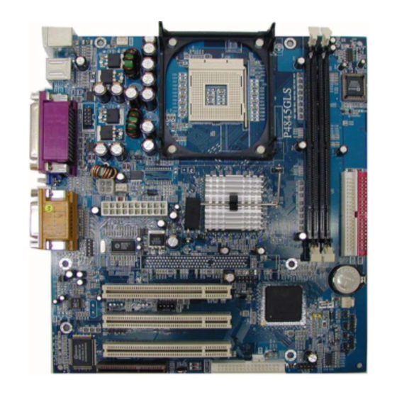
Page 7: Layout Diagram & Jumper Setting
1-4 Layout Diagram & Jumper Setting GAME/MIDI PORT PRINT PS/2 MOUSE PS/2 Keyboard COM1 LINE-IN LINE-OUT CPU FAN CPU Socket PS2 KB/Mouse Port USB Port 2M Flash ROM BIOS COM2 Connector SDR SDRAM DIMM x2 Power FAN PC99 Back Panel Intel 845GL Chipset ATX 12V Power Conn. - Page 8 Jumpers Jumper Name Description Page CPU Frequency Select 3-pin Block CMOS RAM Clear 3-pin Block On board AC97’ Codec Selector 3-pin Block Connectors Connector Name Description Page ATX Power Connector 20-pin Block P.12 ATX 12V Power Connector 4-pin Block P.12 KBMS PS/2 Mouse &...
-
Page 9: Hardware Installation Steps
Chapter 2 Hardware installation 2-1 Hardware installation Steps Before using your computer, you had better complete the following steps: 1. Check motherboard jumper setting 2. Install CPU and Fan 3. Install System Memory (DIMM) 4. Install Expansion cards 5. Connect IDE and Floppy cables, Front Panel /Back Panel cable 6. -
Page 10: Glossary
Note: When should clear CMOS 1. Troubleshooting 2. Forget password 3. After over clocking system boot fail 1-2 closed Normal (Default) 2-3 closed Clear CMOS CMOS RAM Clear Setting (3) On-board AC97’ Codec Selector (3-pin) : JP6 1-2 closed Enabled (Default) 2-3 closed Disabled On-board AC97’... -
Page 11: About Intel Pentium 4 478-Pin Cpu
speakers, MIC, game controllers, and MIDI sound devices. LAN (interface) - Local Area Network - the interface to your local area network. BIOS (Basic Input/Output System) - the program logic used to boot up a computer and establish the relationship between the various components. Driver - software, which defines the characteristics of a device for use by another device or other software. -
Page 12: Install Memory
2-4 Install Memory This motherboard provides 168-pin DUAL INLINE MEMORY MODULES (DIMM) sites for memory expansion available from minimum memory size of 64MB to maximum memory size of 2.0GB SDRAM. Valid Memory Configurations Bank 168-Pin DIMM Total Memory Bank 0, 1 (SDR1) PC133/PC100 64MB∼1.0GB SDR SDRAM Module... -
Page 13: Expansion Card
2-5 Expansion Cards WARNING! Turn off your power when adding or removing expansion cards or other system components. Failure to do so may cause severe damage to both your motherboard and expansion cards. 2-5-1 Procedure For Expansion Card Installation 1. Read the documentation for your expansion card and make any necessary hardware or software setting for your expansion card such as jumpers. -
Page 14: Connectors, Headers
Interrupt request are shared as shown the table below: INT A INT B INT C INT D INT E INT F INT G INT H √ Slot 1 √ Slot 2 √ Slot 3 √ Onboard VGA √ Onboard LAN √... - Page 15 Pin 1 PS/2 Mouse & PS/2 Keyboard Connector: KBMS The connectors for PS/2 keyboard and PS/2 Mouse. USB Port connector: USB1 The connectors are 4-pin connector that connect USB devices to the system board. Parallel Port Connector (25-pin female): LPT1 Parallel Port connector is a 25-pin D-Subminiature Receptacle connector.
- Page 16 Pin 1 Floppy Drive Connector (10) Primary IDE Connector (40-pin block): IDE1 This connector supports the provided IDE hard disk ribbon cable. After connecting the single plug end to motherboard, connect the two plugs at other end to your hard disk(s). If you install two hard disks, you must configure the second drive to Slave mode by setting its jumpers accordingly.
-
Page 17: Headers
2-6-2 Headers Serial Port2 COM2 Header (9-pin) : COM2 CO M2 Note: Orient the read marking on the COM2 ribbon cable to pin 1 Pin 1 Serial Port2 COM2 Header Line-Out, MIC Headers (9-pin): Front AUDIO This header connect to Front Panel Line-out, MIC connector with cable. AUDIO AUD - FPO UT - L AUD - RET - L... - Page 18 Speaker connector: SPK This 4-pin connector connects to the case-mounted speaker. See the figure below. Power LED: PWRLED The Power LED is light on while the system power is on. Connect the Power LED from the system case to this pin. Power switch: PSON This 2-pin connector connects to the case-mounted power switch to power ON/OFF the system.
- Page 19 CPUFAN PWRFAN CHSFAN FAN Speed Headers (11) IR infrared module Headers (5-pin) : IR This connector supports the optional wireless transmitting and receiving infrared module. You must configure the setting through the BIOS setup to use the IR function. Pin 1 Infrared Module Headers (12) CD Audio-In Headers (4-pin) : CD_IN CDIN are the connectors for CD-Audio Input signal.
-
Page 20: Starting Up Your Computer
2-7 Starting Up Your Computer 1. After all connection are made, close your computer case cover. 2. Be sure all the switch are off, and check that the power supply input voltage is set to proper position, usually in-put voltage is 220V∼240V or 110V∼120V depending on your country’s voltage used. -
Page 21: Entering Setup
6. During power-on, press <Delete> key to enter BIOS setup. Follow the instructions in BIOS SETUP. 7. Power off your computer: You must first exit or shut down your operating system before switch off the power switch. For ATX power supply, you can press ATX power switching after exiting or shutting down your operating system. -
Page 22: Getting Help
Press <F1> to continue, <Ctrl-Alt-Esc> or <Del> to enter Setup 3-2 Getting Help Main Menu The on-line description of the highlighted setup function is displayed at the bottom of the screen. Status Page Setup Menu/Option Page Setup Menu Press F1 to pop up a small help window that describes the appropriate keys to use and the possible selections for the highlighted item. -
Page 23: Standard Cmos Features
Use this menu to specify your settings for integrated peripherals. Power Management Setup Use this menu to specify your settings for power management. PnP/PCI configurations This entry appears if your system supports PnP/PCI. PC Health Status This entry shows your PC health status. Miscellaneous Control Use this menu to specify your settings for Miscellaneous control. - Page 24 > IDE Primary Master Press Enter None Menu Level > > IDE Primary Slave Press Enter None > IDE Secondary Master Press Enter None Change the day, month, > IDE Secondary Slave Press Enter None year and century Drive A 1.44M, 3.5 in.
-
Page 25: Advanced Bios Features
3-5 Advanced BIOS Features CMOS Setup Utility – Copyright(C) 1984-2002 Award Software Advanced BIOS Features Anti-Virus Protection Disabled Item Help CPU L1 & L2 Cache Enabled Quick Power On Self Test Enabled Hard Disk Boot Priority Press Enter Menu Level > First Boot Device Floppy Second Boot Device... - Page 26 This category speeds up Power On Self Test (POST) after you power on the computer. If this is set to Enabled. BIOS will shorten or skip some check items during POST. Enabled (default) Enable quick POST Disabled Normal POST First/Second/Third/Fourth Boot Device The BIOS attempts to load the operating system from the devices in the sequence selected in these items.
-
Page 27: Advanced Chipset Features
3-6 Advanced Chipset Features The Advanced Chipset Features Setup option is used to change the values of the chipset registers. These registers control most of the system options in the computer. CMOS Setup Utility – Copyright(C) 1984-2002 Award Software Advanced Chipset Features >... -
Page 28: Dram Timing Settings
3-6-1 DRAM Timing Settings CMOS Setup Utility – Copyright(C) 1984-2002 Award Software DRAM Timing Settings Auto Configuration Standard Item Help SDRAM CAS Latency Time SDRAM Cycle Time SDRAM RAS# to CAS# Delay Menu Level >> SDRAM RAS# Precharge Time ↑↓→← Move Enter:Select +/-/PU/PD:Value F10:Save ESC:Exit F1:General Help F5:Previous Values F6:Optimized Defaults... -
Page 29: Onboard Ide Function
Onboard Super IO Function Please refer to section 3-7-3 Init Display First This item allows you to decide to activate whether PCI Slot or AGP VGA first. The settings are: PCI Slot, AGP Slot. 3-7-1 Onboard IDE Function CMOS Setup Utility – Copyright(C) 1984-2002 Award Software Onboard IDE Function OnChip Primary PCI IDE Enabled... -
Page 30: Onboard Device Function
3-7-2 Onboard Device Function CMOS Setup Utility – Copyright(C) 1984-2002 Award Software Onboard Device Function Item Help USB Controller Enabled USB Keyboard Legacy Support Disabled ** Onboard AC97 Codec is ALC101 ** Menu Level >> AC97 Audio Auto AC97 Modem Auto Game Port Address Midi Port Address... -
Page 31: Power Management Setup
Select Enabled if your system has a floppy disk controller (FDD) installed on the system board and you wish to use it. If you install add-on FDC or the system has no floppy drive, select Disabled in this field. The settings are: Enabled and Disabled. Onboard Serial Port 1/Port 2 Select an address and corresponding interrupt for the first and the second serial ports. - Page 32 Video off Method V/H SYNC+Blank Menu Level > Video Off In Suspend Suspend Type Stop Grant MODEM Use IRQ Suspend Mode Disabled HDD Power Down Disabled Soft-off by PWR-BTTN Instant-off Wake-Up by PCI card Disabled Power On by Ring Disabled Resume by Alarm Disabled X Date (of Month)
-
Page 33: Pm Timer Reload Events
3-8-1 PM Timer Reload Events CMOS Setup Utility – Copyright(C) 1984-2002 Award Software PM Timer Reload Events Primary IDE 0 Disabled Item Help Primary IDE 1 Disabled Secondary IDE 0 Disabled Secondary IDE 1 Disabled Menu Level >> FDD, COM, LPT Port Disabled PCI PIRQ [A-D] # Disabled... -
Page 34: Irq Resources
® unless you are using a Plug and Play operating system such as Windows 95/98. If you set this field to “manual” choose specific resources by going into each of the sub menu that follows this field (a sub menu is preceded by a “>”). The settings are: Auto(ESCD), Manual. -
Page 35: Miscellaneous Control
Shutdown Temperature Disabled Item Help CPU Warning Temperature Disabled Show PC Health in Post Enabled 25 ° C Current System Temperature 38 ° C Current CPU Temperature Menu Level > Current CPUFAN Speed 5000 rpm Current PWRFAN Speed 5000 rpm Current CHRFAN Speed 5000 rpm Vcore... -
Page 36: Load Standard/Optimized Defaults
Spread Spectrum Disabled Menu Level > ** Current Host Clock is 100/33MHz ** HOST/PCI Clock at Next Boot is 100/33MHz ** Current DRAM Clock is 133MHz ** DRAM Clock at Next Boot is 133MHz ↑↓→← Move Enter:Select +/-/PU/PD:Value F10:Save ESC:Exit F1:General Help F5:Previous Values F6:Optimized Defaults... - Page 37 When you press <Enter> on this item, you get a confirmation dialog box with a message similar to: Load Optimized Defaults (Y/N)? N Pressing <Y> loads the default values that are factory settings for optimal performance system operations. 3-13 Set Supervisor/User Password You can set either supervisor or user password, or both of them.
-
Page 38: Chapter 4 Driver & Free Program Installation
Chapter 4 DRIVER & FREE PROGRAM INSTALLATION Check your package and there is A MAGIC INSTALL CD included. This CD consists of all DRIVERS you need and some free application programs and utility programs. In addition, this CD also include an auto detect software which can tell you which hardware is installed, and which DRIVERS needed so that your system can function properly. -
Page 39: Inf Install Intel 845 Chipset System Driver
4-1 INF install INTEL 845 chipset system driver After you have completed the installation of your operation system (WINDOWS 98SE). You will find an UNKNOWN DEVICE in the device manager (START/SETTING/CONTROL PANEL/ SYSTEM/DEVICE MANAGER). You have to install INF driver as shown below: 1. -
Page 40: Vga Install Intel 845G Vga Driver
4-2 VGA install Intel 845G VGA Driver 1. Click VGA when MAGIC INSTALL MENU Click NEXT When Intel (R) Brookdale-G- appears 830M Chipset Graphics Driver Software Setup Click YES, This is Announce CopyRight If You Want Re-start Computer , Click FINISH 4-3 SOUND Install ALC Audio Codec Driver 1. -
Page 41: Pc-Cillin Install Pc-Cillin2002 Anti-Virus Program
3. Click Finish and Restart Windows 4. Click Start→Program→Avance Sound Manager→AvRack. Then AVRACK Windows appears NOTE: MAGIC INSTALL will auto detect file path: X:\CODEC\ALCCODEC\SETUP.EXE (for WINDOWS 98SE/ME/NT4.0/2000/XP) You need setting the “Environment Form Sound Effect” before you want to change 4/6 channel speaker output (Example: Room\Livingroom…..) Avance Audio Rack table can play CD, WAV, MID, MP3, AVI, MPG Format File... - Page 42 This is license agreement, select "I Accept Click NEXT and Enter your Customer the terms" and Click NEXT Information, Click NEXT or choose Change to change the path for the file to be stored Click INSTALL, Start to install the software 6.
-
Page 43: Magic Bios Install Bios Live Update Utility
4-5 MAGIC BIOS Install BIOS Live Update Utility 1. Click Magic BIOS when Magic Install MENU 2. Click Next to install the Magic BIOS in appears Destination Folder 3. After finish Setup you will have a Magic 4. Double click the Magic BIOS icon you will BIOS icon in your screen have this picture, choose from internet you can upgrade BIOS On-line... -
Page 44: How To Install Usb 2.0 Driver
When choose From Local Driver to update 10. Choose the correct BIOS file to update BIOS BIOS, you must have the correct BIOS file in your Local Driver 4-6 IAA Install Application Accelerator Software The Intel Application Accelerator is designed to improve performance of the storage sub-system and overall system performance. -
Page 45: How To Disable On-Board Sound
STEP 2. Copy utility program to your boot disc. You may copy from DRIVER CD X:\FLASH\AWDFLASH.EXE or download from our web site. STEP 3. Copy latest BIOS for P4845GLS from our web site to your boot disc. STEP 4. Insert your boot disc into A:, start the computer, type “Awdflash A:\P4845GLSAxxx.BIN /SN/PY/CC/R”...