Asus TUF GAMING X670E-PLUS Manual
Hide thumbs
Also See for TUF GAMING X670E-PLUS:
- Quick start manual (2 pages) ,
- Quick start manual (2 pages) ,
- Manual (78 pages)
Table of Contents
Advertisement
Advertisement
Table of Contents

Related Manuals for Asus TUF GAMING X670E-PLUS


Summary of Contents for Asus TUF GAMING X670E-PLUS
- Page 1 TUF GAMING X670E-PLUS...
- Page 2 Product warranty or service will not be extended if: (1) the product is repaired, modified or altered, unless such repair, modification of alteration is authorized in writing by ASUS; or (2) the serial number of the product is defaced or missing.
-
Page 3: Table Of Contents
Contents Safety information ...................... iv About this guide ......................v TUF GAMING X670E-PLUS specifications summary ..........vi Connectors with shared bandwidth ..............x Package contents ....................... xi Installation tools and components ................xii Chapter 1: Product Introduction Before you proceed ................... 1-1 Motherboard layout .................. -
Page 4: Safety Information
Safety information Electrical safety • To prevent electrical shock hazard, disconnect the power cable from the electrical outlet before relocating the system. • When adding or removing devices to or from the system, ensure that the power cables for the devices are unplugged before the signal cables are connected. If possible, disconnect all power cables from the existing system before you add a device. -
Page 5: About This Guide
Refer to the following sources for additional information and for product and software updates. ASUS website The ASUS website (www.asus.com) provides updated information on ASUS hardware and software products. Optional documentation Your product package may include optional documentation, such as warranty flyers, that may have been added by your dealer. -
Page 6: Tuf Gaming X670E-Plus Specifications Summary
Expansion Slots 1 x PCIe 4.0 x16 slot (supports x4 mode) 1 x PCIe 4.0 x4 slot * Please check the PCIe bifurcation table at https://www.asus.com/support/ FAQ/1037507/. Total supports 4 x M.2 slots and 4 x SATA 6Gb/s ports* AMD Ryzen™ 7000 Series Desktop Processors M.2_1 slot (Key M), type 2242/2260/2280... - Page 7 TUF GAMING X670E-PLUS specifications summary Front USB (Total 9 ports) 1 x USB 3.2 Gen 2 connector (supports USB Type-C ® 1 x USB 3.2 Gen 1 header supports additional 2 USB 3.2 Gen 1 ports 3 x USB 2.0 headers support additional 6 USB 2.0 ports Realtek S1220A 7.1 Surround Sound High Definition Audio CODEC*...
- Page 8 TUF GAMING X670E-PLUS specifications summary Miscellaneous 3 x Addressable Gen 2 headers 1 x Aura RGB header 1 x Clear CMOS header Internal I/O Connectors 1 x COM Port header 1 x Front Panel Audio header (AAFP) 1 x 20-3 pin System Panel header with Chassis intrude function 1 x Thermal Sensor header 1 x Thunderbolt™...
- Page 9 Operating System Windows 11, Windows 10 64-bit ® ® ATX Form Factor Form Factor 12 inch x 9.6 inch (30.5 cm x 24.4 cm) Specifications are subject to change without notice. Please refer to the ASUS website for the latest specifications.
-
Page 10: Connectors With Shared Bandwidth
Connectors with shared bandwidth ATX_12V_1 ATX_12V_2 ADD_GEN 2_1 AIO_PUMP CPU_OPT CPU_FAN HDMI_DP DIGI +VRM DRAM BOOT U32G2_34 U32G2_C2 U32G1_20 U32G2X2_C18 LAN_U32G2_21 SOCKET AM5 U32G1_1011_2223 FLBK_LED AUDIO M.2_1(SOCKET3) Ethernet PCIE SATA 5.0 X4 256Mb BIOS 2280 2260 2242 CHA_FAN4 PCIEX16_1 X670 X670 Super M.2_2(SOCKET3) -
Page 11: Package Contents
Package contents Check your motherboard package for the following items. Motherboard 1 x TUF GAMING X670E-PLUS motherboard Cables 2 x SATA 6Gb/s cables 2 x Rubber packages for M.2 Miscellaneous 2 x Screw packages for M.2 SSD 1 x TUF certification card... -
Page 12: Installation Tools And Components
Installation tools and components Phillips (cross) screwdriver PC chassis Power supply unit AMD AM5 CPU AMD AM5/AM4/AM3 compatible CPU Fan DDR5 DIMM SATA hard disk drive SATA optical disc drive (optional) Graphics card (optional) M.2 SSD module (optional) Screws The tools and components in the table above are not included in the motherboard package. -
Page 13: Chapter 1: Product Introduction
Failure to do so may cause severe damage to the motherboard, peripherals, or components. The pin definitions in this chapter are for reference only. The pin names depend on the location of the header/jumper/connector. TUF GAMING X670E-PLUS... -
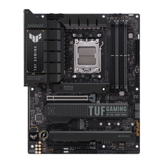
Page 14: Motherboard Layout
Motherboard layout 24.4cm(9.6in) ATX_12V_1 ATX_12V_2 ADD_GEN 2_1 AIO_PUMP CPU_OPT CPU_FAN HDMI_DP DIGI +VRM DRAM BOOT U32G2_34 U32G2_C2 U32G1_20 U32G2X2_C18 LAN_U32G2_21 SOCKET AM5 U32G1_1011_2223 FLBK_LED AUDIO M.2_1(SOCKET3) Ethernet PCIE SATA 5.0 X4 256Mb BIOS 2280 2260 2242 CHA_FAN4 PCIEX16_1 X670 X670 Super M.2_2(SOCKET3) PCIEX4... - Page 15 13. Clear CMOS header 1-16 14. COM Port header 1-17 15. Front Panel Audio header 1-17 16. System Panel header 1-18 17. Thermal Sensor header 1-19 18. Thunderbolt™ header 1-20 19. BIOS FlashBack™ LED 1-21 20. Q-LEDs 1-22 TUF GAMING X670E-PLUS...
- Page 16 Contact your retailer immediately if the PnP cap is missing, or if you see any damage to the PnP cap/socket contacts/motherboard components. ASUS will shoulder the cost of repair only if the damage is shipment/ transit-related.
- Page 17 A DDR5 memory module is notched differently from a DDR, DDR2, DDR3 or DDR4 module. DO NOT install a DDR, DDR2, DDR3 or DDR4 memory module to the DDR5 slot. Recommended memory configurations DIMM_A1 DIMM_A2 DIMM_A2 DIMM_A2 DIMM_B1 DIMM_B2 DIMM_B2 TUF GAMING X670E-PLUS...
- Page 18 (D/C) from the same vendor. Check with the vendor to get the correct memory modules. • Visit the ASUS website for the latest QVL, and memory frequency support depends on the CPU types. Chapter 1: Product Introduction...
- Page 19 Please refer to the following tables for the recommended VGA configuration and Hyper M.2 configuration. Recommended VGA configuration Slot Description Single VGA Dual VGA PCIe 5.0 x16_1 PCIe 4.0 x16_2 Connect a chassis fan to the chassis fan header when using multiple graphics cards for better thermal environment. TUF GAMING X670E-PLUS...
- Page 20 Additional PCIe bifurcation and M.2 settings for RAID function are also supported when a Hyper M.2 x16 series card is installed. • For full details on the PCIe bifurcation, you may visit the support site at https://www.asus.com/support/FAQ/1037507/. • The Hyper M.2 x16 series card is sold separately •...
- Page 21 The system may become unstable or may not boot up if the power is inadequate. • If you want to use two high-end PCI Express x16 cards, use a PSU with 1000W power or above to ensure the system stability. TUF GAMING X670E-PLUS...
- Page 22 M.2 slots The M.2 slots allow you to install M.2 devices such as M.2 SSD modules. M.2_1(SOCKET3) M.2_4(SOCKET3) M.2_2(SOCKET3) M.2_3(SOCKET3) • AMD Ryzen™ 7000 Series Desktop Processors: - M.2_1 slot supports PCIe 5.0 x4 mode M Key design and type 2242/2260/2280 storage devices.
- Page 23 M.2_2 slot shares bandwidth with SATA6G_1&2. When M.2_2 runs at PCIe x4 mode, SATA6G_1&2 will be disabled. Before creating a RAID set, refer to the RAID Configuration Guide. You can download the RAID Configuration Guide from the ASUS website. TUF GAMING X670E-PLUS 1-11...
- Page 24 USB 3.2 Gen 2 Type-C Front Panel connector ® The USB 3.2 Gen 2 Type-C connector allows you to connect a USB 3.2 Gen 2 ® Type-C module for an additional USB 3.2 Gen 2 Type-C port. The USB 3.2 Gen 2 ®...
- Page 25 The USB 2.0 headers provide data transfer speeds of up to 480 Mb/s. USB_2627 USB_1415 PIN 1 PIN 1 USB_1617 PIN 1 A B C DO NOT connect a 1394 cable to the USB connectors. Doing so will damage the motherboard! The USB 2.0 module is purchased separately. TUF GAMING X670E-PLUS 1-13...
- Page 26 Addressable Gen 2 headers The Addressable Gen 2 headers allow you to connect individually addressable RGB WS2812B LED strips or WS2812B based LED strips. ADD_GEN 2_1 ADD_GEN 2_3 PIN 1 ADD_GEN 2_2 The Addressable Gen 2 header supports WS2812B addressable RGB LED strips (5V/ Data/Ground), with a maximum power rating of 3A (5V) and the addressable headers on this board can handle a combined maximum of 500 LEDs.
- Page 27 RGB LED strip is connected in the correct orientation, and the 12V connector is aligned with the 12V header on the motherboard. • The LED strip will only light up when the system is powered on. • The LED strip is purchased separately. TUF GAMING X670E-PLUS 1-15...
- Page 28 Clear CMOS header The Clear CMOS header allows you to clear the Real Time Clock (RTC) RAM in the CMOS, which contains the date, time, system passwords, and system setup parameters. CLRTC PIN 1 To erase the RTC RAM: Turn OFF the computer and unplug the power cord. Short-circuit pin 1-2 with a metal object or jumper cap for about 5-10 seconds.
- Page 29 HD Audio. Connect one end of the front panel audio I/O module cable to this header. AAFP PIN 1 HD-audio-compliant pin definition We recommend that you connect a high-definition front panel audio module to this connector to avail of the motherboard’s high-definition audio capability. TUF GAMING X670E-PLUS 1-17...
- Page 30 System Panel header The System Panel header supports several chassis-mounted functions. PLED PWRSW SPEAKER PANEL CHASSIS PIN 1 HDD_LED RESET PLED • System Power LED header (PLED) The 2-pin and/or 3-1 pin headers allow you to connect the System Power LED. The System Power LED lights up when the system is connected to a power source, or when you turn on the system power, and blinks when the system is in sleep mode.
- Page 31 Connect the thermal sensor and place it on the device or the motherboard’s component to detect its temperature. T_SENSOR PIN 1 The thermal sensor is purchased separately. TUF GAMING X670E-PLUS 1-19...
- Page 32 Thunderbolt header The Thunderbolt™ header allows you to connect an add-on Thunderbolt™ I/O card that supports Intel®’s Thunderbolt™ Technology, allowing you to connect Thunderbolt™-enabled devices to form a daisy chain-configuration. TB_HEADER PIN 1 • The add-on Thunderbolt™ I/O card and Thunderbolt™ cables are purchased separately.
- Page 33 The BIOS FlashBack™ LED lights up or blinks to indicate the status of the BIOS FlashBack™. FLBK_LED LED status Description Blinking BIOS is flashing Solid On BIOS flashing is abnormal more information on the BIOS Refer to the BIOS update utility section for FlashBack™ feature TUF GAMING X670E-PLUS 1-21...
- Page 34 Q-LEDs The Q-LEDs check key components (CPU, DRAM, VGA, and booting devices) during the motherboard booting process. If an error is found, the critical component’s LED stays lit up until the problem is solved. CPU (RED) DRAM (YELLOW) VGA (WHITE) BOOT (YELLOW GREEN) The Q-LEDs provide the most probable cause of an error code as a starting point for troubleshooting.
-
Page 35: Building Your Pc System
DO NOT force the CPU into the socket to prevent bending the pins and damaging the CPU. • ASUS will not cover damages resulting from incorrect CPU installation/removal, incorrect CPU orientation/placement, or other damages resulting from negligence by the user. - Page 36 Chapter 2: Basic Installation...
-
Page 37: Cooling System Installation
2.1.2 Cooling system installation • Apply Thermal Interface Material to the CPU cooling system and CPU before you install the cooling system, if necessary. To install a CPU heatsink and fan assembly (Type 1) TUF GAMING X670E-PLUS... - Page 38 To install a CPU heatsink and fan assembly (Type 2) When using this type of CPU fan, remove the screws and the retention module only. Do not remove the plate on the bottom. Chapter 2: Basic Installation...
- Page 39 To install an AIO cooler If you wish to install an AIO cooler, we recommend installing the AIO cooler after installing the motherboard into the chassis. AIO_PUMP CPU_FAN CPU_OPT TUF GAMING X670E-PLUS...
-
Page 40: Dimm Installation
2.1.3 DIMM installation To remove a DIMM Chapter 2: Basic Installation... -
Page 41: Installation
M.2 slots if you wish to install an M.2 to another M.2 slot. • Use a Phillips screwdriver when removing or installing the screws or screw stands mentioned in this section. • The M.2 is purchased separately. Loosen the screws from the M.2 heatsinks. Lift and remove the heatsinks. TUF GAMING X670E-PLUS... - Page 42 Install your M.2 to your M.2 slot. The steps may differ between installing M.2 of different lengths, please refer to the different types and their installation steps below: • To install an M.2 to M.2_1, M.2_3, M.2_4 slot For 2280 length (optional) Install the bundled M.2 rubber pad if you are installing a single sided M.2 storage device.
- Page 43 OPTIONAL TUF GAMING X670E-PLUS...
- Page 44 • To install an M.2 to M.2_2 slot For 22110 length Rotate and adjust the M.2 Q-latch so that the handle points away from the M.2 slot. Install your M.2 to the M.2 slot. Rotate the M.2 Q-Latch clockwise to secure the M.2 in place. For 2242, 2260, 2280 length Remove the pre-installed removable M.2 Q-Latch screw at the 22110 length screw hole.
- Page 45 If the thermal pad on the M.2 heatsink becomes damaged and needs to replaced, we recommend replacing it with a thermal pad with a thickness of 1.25mm. Replace the heatsinks. Secure the heatsinks using the screws removed previously. TUF GAMING X670E-PLUS 2-11...
-
Page 46: Motherboard Installation
2.1.5 Motherboard installation Place the motherboard into the chassis, ensuring that its rear I/O ports are aligned to the chassis’ rear I/O panel. Place nine (9) screws into the holes indicated by circles to secure the motherboard to the chassis. DO NOT over tighten the screws! Doing so can damage the motherboard. -
Page 47: Atx Power Connection
2.1.6 ATX power connection Ensure to connect the 8-pin power plug, or connect both 8-pin power plugs. TUF GAMING X670E-PLUS 2-13... -
Page 48: Sata Device Connection
2.1.7 SATA device connection Chapter 2: Basic Installation 2-14... -
Page 49: Front I/O Connector
This connector will only fit in one orientation. Push the connector until it clicks into place. To install USB 2.0 connector To install USB 3.2 Gen 1 connector USB 2.0 USB 3.2 Gen 1 To install front panel audio connector AAFP TUF GAMING X670E-PLUS 2-15... -
Page 50: Expansion Card Installation
2.1.9 Expansion card installation To install PCIe x16 cards To install PCIe x4 card Chapter 2: Basic Installation 2-16... - Page 51 9V devices when the 6-pin PCIe power connector is connected. • The Thunderbolt™ series card is sold separately. • Please visit the official website of your purchased Thunderbolt card for more details on compatibility. TUF GAMING X670E-PLUS 2-17...
-
Page 52: Bios Update Utility
• Updating BIOS may have risks. If the BIOS program is damaged during the process and results to the system’s failure to boot up, please contact your local ASUS Service Center. Chapter 2: Basic Installation... -
Page 53: Motherboard Rear And Audio Connections
For more information on using the BIOS FlashBack™ feature, please refer to https://www.asus.com/support/, or by scanning the QR code below. Motherboard rear and audio connections 2.3.1 Rear I/O connection Rear panel connectors DisplayPort USB 3.2 Gen 2 Type-A ports 3, 4, and 21 USB 3.2 Gen 1 Type-A ports 20, 10, 11 and 22... - Page 54 * Ethernet port LED indications Activity Link LED Speed LED ACT/LINK SPEED Status Description Status Description No link No link GREEN Linked GREEN 2.5 Gbps connection Ethernet port BLINKING Data activity ORANGE 1 Gbps / 100 Mbps / 10 Mbps connection ** Audio 2, 4, 5.1 or 7.1-channel configuration Port 2-channel...
-
Page 55: Audio I/O Connections
2.3.2 Audio I/O connections Audio I/O ports Connect to Headphone and Mic Connect to 2-channel Speakers Connect to 4-channel Speakers TUF GAMING X670E-PLUS 2-21... - Page 56 Connect to 5.1-channel Speakers Connect to 7.1-channel Speakers Chapter 2: Basic Installation 2-22...
-
Page 57: Starting Up For The First Time
While the system is ON, press the power button for less than four seconds to put the system on sleep mode or soft-off mode, depending on the BIOS setting. Press the power button for more than four seconds to let the system enter the soft-off mode regardless of the BIOS setting. TUF GAMING X670E-PLUS 2-23... - Page 58 Chapter 2: Basic Installation 2-24...
-
Page 59: Chapter 3: Bios And Raid Support
Knowing BIOS The new ASUS UEFI BIOS is a Unified Extensible Interface that complies with UEFI architecture, offering a user-friendly interface that goes beyond the traditional keyboard- only BIOS controls to enable a more flexible and convenient mouse input. You can easily navigate the new UEFI BIOS with the same smoothness as your operating system. -
Page 60: Bios Setup Program
BIOS Setup program Use the BIOS Setup to update the BIOS or configure its parameters. The BIOS screens include navigation keys and brief onscreen help to guide you in using the BIOS Setup program. Entering BIOS at startup To enter BIOS Setup at startup, press <Delete> or <F2> during the Power-On Self Test (POST). -
Page 61: Asus Ez Flash 3
ASUS EZ Flash 3 The ASUS EZ Flash 3 feature allows you to update the BIOS without using an OS-based utility. Ensure to load the BIOS default settings to ensure system compatibility and stability. Select the Load Optimized Defaults item under the Exit menu or press hotkey <F5>. -
Page 62: Asus Crashfree Bios 3
ASUS CrashFree BIOS 3 The ASUS CrashFree BIOS 3 utility is an auto recovery tool that allows you to restore the BIOS file when it fails or gets corrupted during the updating process. You can restore a corrupted BIOS file using a USB flash drive that contains the BIOS file. -
Page 63: Raid Configurations
For more information on configuring your RAID sets, please refer to the RAID Configuration Guide which you can find at https://www.asus.com/support, or by scanning the QR code. RAID definitions Volume provides the ability to link-together storage from one or several disks, regardless of the size of the space on those disks. - Page 64 Chapter 3: BIOS and RAID Support...
-
Page 65: Appendix
Appendix Notices FCC Compliance Information Responsible Party: Asus Computer International Address: 48720 Kato Rd., Fremont, CA 94538, USA Phone / Fax No: (510)739-3777 / (510)608-4555 This device complies with part 15 of the FCC Rules. Operation is subject to the following two conditions: (1) This device may not cause harmful interference, and (2) this device must accept any interference received, including interference that may cause undesired operation. - Page 66 Compliance Statement of Innovation, Science and Economic Development Canada (ISED) This device complies with Innovation, Science and Economic Development Canada licence exempt RSS standard(s). Operation is subject to the following two conditions: (1) this device may not cause interference, and (2) this device must accept any interference, including interference that may cause undesired operation of the device.
- Page 67 ASUS products sold in Vietnam, on or after September 23, 2011,meet the requirements of the Vietnam Circular 30/2011/TT-BCT. Các sản phẩm ASUS bán tại Việt Nam, vào ngày 23 tháng 9 năm2011 trở về sau, đều phải đáp ứng các yêu cầu của Thông tư 30/2011/TT-BCT của Việt Nam.
- Page 68 ASUS Recycling/Takeback Services ASUS recycling and takeback programs come from our commitment to the highest standards for protecting our environment. We believe in providing solutions for you to be able to responsibly recycle our products, batteries, other components as well as the packaging materials.
- Page 69 Français AsusTek Computer Inc. déclare par la présente que cet appareil est conforme aux critères essentiels et autres clauses pertinentes des directives concernées. La déclaration de conformité de l’UE peut être téléchargée à partir du site Internet suivant : www.asus.com/support.
-
Page 70: Warranty
• ASUS offers a voluntary manufacturer’s Commercial Guarantee. • ASUS dragovoljno nudi komercijalno proizvođačko jamstvo. • ASUS reserves the right to interpret the provisions of the ASUS • ASUS zadržava prava na tumačenje odredbi ASUS komercijalnog Commercial Guarantee. jamstva. •... - Page 71 • ASUS tilbyr som produsent en frivillig kommersiell garanti. • Bảo hành thương mại này của ASUS được cung cấp độc lập và ngoài • ASUS forbeholder seg retten til å tolke bestemmelsene i ASUS sin Bảo đảm pháp lý theo luật định và không có cách nào ảnh hưởng đến kommersielle garanti.
-
Page 72: Asus Contact Information
Address: 1F., No. 15, Lide Rd., Beitou Dist., Taipei City 112, Taiwan ASUS COMPUTER INTERNATIONAL (America) Address: 48720 Kato Rd., Fremont, CA 94538, USA ASUS COMPUTER GmbH (Germany and Austria) Address: Harkortstrasse 21-23, 40880 Ratingen, Germany ASUSTeK (UK) LIMITED Address: 1st Floor, Sackville House, 143-149 Fenchurch Street, London, EC3M 6BL,...