Table of Contents
Advertisement
Advertisement
Table of Contents

Related Manuals for Asus X99-M WS


Summary of Contents for Asus X99-M WS
- Page 1 X99-M WS...
- Page 2 Product warranty or service will not be extended if: (1) the product is repaired, modified or altered, unless such repair, modification of alteration is authorized in writing by ASUS; or (2) the serial number of the product is defaced or missing.
-
Page 3: Table Of Contents
Contents Safety information ...................... vi About this guide ......................vii X99-M WS specifications summary ................ix Package contents ..................... xiii Installation tools and components ................. xiv Chapter 1: Product introduction Special features..................1-1 1.1.1 Product highlights................ 1-1 1.1.2 Other special features ..............1-2 Motherboard overview ................ - Page 4 3.6.10 NVMe Configuration ..............3-46 Monitor menu ................... 3-47 Boot menu ....................3-51 Tool menu ....................3-57 3.9.1 ASUS EZ Flash 2 Utility ............3-57 3.9.2 ASUS O.C. Profile ..............3-58 3.9.3 ASUS SPD Information ............. 3-59 3.10 Exit menu ....................3-60 3.11...
- Page 5 Requirements ................6-5 6.2.2 Installing two SLI-ready graphics cards ........6-5 6.2.3 Installing the device drivers ............6-6 6.2.4 Enabling the NVIDIA SLI™ technology ........6-7 ® Appendices Notices ........................A-1 X99-M WS block diagram ..................A-2 ASUS contact information ..................A-7...
-
Page 6: Safety Information
Safety information Electrical safety • To prevent electrical shock hazard, disconnect the power cable from the electrical outlet before relocating the system. • When adding or removing devices to or from the system, ensure that the power cables for the devices are unplugged before the signal cables are connected. If possible, disconnect all power cables from the existing system before you add a device. -
Page 7: About This Guide
Refer to the following sources for additional information and for product and software updates. ASUS website The ASUS website (www.asus.com) provides updated information on ASUS hardware and software products. Optional documentation Your product package may include optional documentation, such as warranty flyers, that may have been added by your dealer. -
Page 8: Conventions Used In This Guide
Conventions used in this guide To ensure that you perform certain tasks properly, take note of the following symbols used throughout this manual. DANGER/WARNING: Information to prevent injury to yourself when trying to complete a task. CAUTION: Information to prevent damage to the components when trying to complete a task IMPORTANT: Instructions that you MUST follow to complete a task. -
Page 9: X99-M Ws Specifications Summary
X99-M WS specifications summary LGA2011-v3 socket for Intel Core™ i7/Xeon E5-2600/1600 v3 ® ® processors Supports 22nm CPU Supports Intel Turbo Boost Technology 2.0* ® * The Intel Turbo Boost Technology 2.0 support depends on the CPU ® types. Intel... - Page 10 X99-M WS specifications summary - High Quality 109dB SNR Stereo Playback Output (Line-out@ back) & 104dB SNR Recording Input (Line-in) Support - Absolute Pitch 192khz/24bit True BD Lossless Sound - BD Audio Layer Content Protection Audio - DTS UltraPC II...
- Page 11 - Q-Connector 2 x RJ-45 ports for GbE LAN 1 x 8-channel audio jack 1 x Optical S/PDIF out 1 x ASUS Wi-Fi Go! module (Wi-Fi 802.11 a/b/g/n/ac and Bluetooth v4.0) Rear Panel I/O Ports 2 x USB 3.1 ports 4 x USB 3.0 ports...
- Page 12 ASUS Special Features EZ XMP USB Charger+ Ai Charger+ Disk unlocker ASUS PIKE SAS upgrade kit (optional) Workstation Exclusive 12K hours capacitors ProCool Power connector 1 x USB 3.0/2.0 connectors support additional 2 USB ports (19-pin) 2 x USB 2.0/1/1 connectors support additional 4 USB ports 1 x M.2 Socket 3 (for M key, type 2260/2280 devices)
-
Page 13: Package Contents
Check your motherboard package for the following items ASUS X99-M WS motherboard 8 x Serial ATA 6 Gb/s cables 1 x 2-in-1 ASUS Q-Connector kit 1 x ASUS Q-Shield 1 x USB 2.0 module 1 x ASUS SLI™ bridge connector... -
Page 14: Installation Tools And Components
Installation tools and components Intel LGA2011-v3 CPU ® Intel LGA2011-v3 compatible CPU Fan ® Philips (cross) screwdriver SATA hard disk drive PC chassis DIMM 1 bag of screws Power supply unit SATA optical disc drive (optional) Graphics card The tools and components in the table above are not included in the motherboard package. -
Page 15: Chapter 1: Product Introduction
This motherboard features the M.2 slot with a data transfer speed up to 10 Gb/s. This helps enhance the performance of your SSD (Solid State Drive) that is dedicated only to the operating system. * Supports PCIe/SATA mode. ASUS X99-M WS... -
Page 16: Other Special Features
Complete USB 3.1 integration This motherboard has the latest USB 3.1 connectivity built in with dual Type-A ports for the very fastest USB data transfers — that’s up to 10 Gb/s, or twice as fast as USB 3.0. The next-generation standard is completely backward-compatible with your existing USB devices, and you’ll be all set for USB 3.1’s breakneck speeds. -
Page 17: Motherboard Overview
Before you install or remove any component, ensure that the ATX power supply is switched off or the power cord is detached from the power supply. Failure to do so may cause severe damage to the motherboard, peripherals, or components. ASUS X99-M WS... -
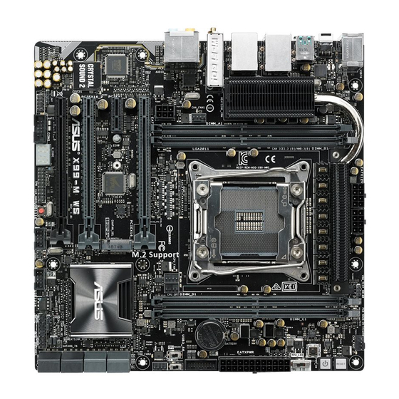
Page 18: Motherboard Layout
1.2.2 Motherboard layout Refer to 1.2.9 Internal connectors and 2.3.1 Rear I/O connection for more information about rear panel connectors and internal connectors. Chapter 1: Product introduction... -
Page 19: Layout Contents
21. Q-Code LEDs 1-20 22. Serial port connector (10-1 pin COM1) 1-24 23. Front panel audio connector (10-1 pin AAFP) 1-26 24. Digital audio connector (4-1 pin SPDIF_OUT) 1-24 25. M.2 Socket 3 connector 1-33 26. LGA2011-v3 CPU socket ASUS X99-M WS... -
Page 20: Central Processing Unit (Cpu)
Contact your retailer immediately if the PnP cap is missing, or if you see any damage to the PnP cap/socket contacts/motherboard components. ASUS will shoulder the cost of repair only if the damage is shipment/ transit-related. -
Page 21: System Memory
The motherboard comes with eight DDR 4 (Double Data Rate 4) Quad Inline Memory Modules (DIMM) slots. A DDR4 module is notched differently from a DDR, DDR2, or DDR3 module. DO NOT install a DDR, DDR2, or DDR3 memory module to the DDR4 slot. Recommended memory configurations ASUS X99-M WS... -
Page 22: Memory Configurations
• Hyper DIMM support is subject to the physical characteristics of individual CPUs. Load the X.M.P. or D.O.C.P. settings in the BIOS for the hyper DIMM support. • Visit the ASUS website for the latest QVL. Chapter 1: Product introduction... -
Page 23: Expansion Slots
Slot Description Slot No. 40-LANE 28-LANE PCIe 3.0/2.0 x16_1 slot PCIe 3.0/2.0 x16_1 slot PCIe 2.0 x1_1 slot PCIe 2.0 x1_1 slot PCIe 3.0/2.0 x16_2 slot PCIe 3.0/2.0 x16_2 slot PCIe 3.0/2.0 x16_3 slot PCIe 3.0/2.0 x16_3 slot ASUS X99-M WS... - Page 24 40-LANE CPU VGA configuration 40-LANE CPU PCI Express 3.0 operating mode PCIe 3.0/2.0 PCIe 3.0/2.0 PCIe 3.0/2.0 configuration x16_1 x16_2 x16_3 Single VGA/PCIe card Dual VGA/PCIe cards Triple VGA/PCIe cards 28-LANE CPU VGA configuration PCI Express 3.0 operating mode 28-LANE CPU PCIe 3.0/2.0 PCIe 3.0/2.0 PCIe 3.0/2.0...
- Page 25 – – – – – – shared – ASMedia Controller shared – – – – – – – (1042AE) shared – – – – – – – WiFi – – – shared – – – – ASUS X99-M WS 1-11...
-
Page 26: Onboard Buttons And Switches
1.2.6 Onboard buttons and switches Onboard buttons and switches allow you to fine-tune performance when working on a bare or open-case system. This is ideal for overclockers and gamers who continually change settings to enhance system performance. Power-on button The motherboard comes with a power-on button that allows you to power up or wake up the system. - Page 27 BIOS default settings. A message will appear during POST reminding you that the BIOS has been restored to its default settings. • We recommend that you download and update to the latest BIOS version from www.asus.com after using the MemOK! function. ASUS X99-M WS 1-13...
- Page 28 TPU switch With its two-level adjustment functions, the TPU allows you to automatically adjusts the CPU ratio and clock speed for an optimal system performance. • Enable this switch when the system is powered off. • When the TPU switch is set to Enabled (TPU_I: CPU Ratio Boost), the system automatically adjusts the CPU ratio for an enhanced performance.
- Page 29 • You may change the EPU settings in BIOS setup program and enable the EPU function at the same time. However, the system will use the last setting you have made. ASUS X99-M WS 1-15...
- Page 30 Clear CMOS button (CLR_CMOS) Press this button to clear the BIOS setup information only when the systems hangs due to overclocking. EZ XMP switch Enable this switch to overclock the installed DIMMs, allowing you to enhance the DIMM’s speed and performance. The EZ XMP LED (XLED1) lights up when you enable the EZ XMP switch.
-
Page 31: Jumpers
These jumpers allow you to switch fan pin selection. The CHAFAN_SEL jumper is for the front fans and rear fans control. Set pins 1-2 to let the BIOS control the settings of the chassis fans. Set pins 2-3 to control the settings of the 4-pin PWM fans. ASUS X99-M WS 1-17... -
Page 32: Onboard Leds
1.2.8 Onboard LEDs Diagnosis LEDs The Diagnosis LEDs provide the status of these key components during POST (Power- On-Self Test): CPU, memory modules, VGA card, and hard disk drives. If an error is found, the critical component’s LED stays lit up until the problem is solved. TPU LED (TPU_LED) The TPU LED lights up when the TPU switch is enabled. - Page 33 EPU LED (O2LED3) The EPU LED lights up when the EPU switch is enabled. EZ XMP LED (XLED1) This LED lights up when you enable the EZ XMP switch. ASUS X99-M WS 1-19...
- Page 34 Q-Code LEDs The Q-Code LED design provides you with a 2-digit error code that displays the system status. Refer to the Q-Code table on the next page for details. Chapter 1: Product introduction 1-20...
- Page 35 Recovery process started Recovery firmware image is found Recovery firmware image is loaded Reserved for future AMI progress codes F5 – F7 Recovery PPI is not available Recovery capsule is not found (continued on the next page) ASUS X99-M WS 1-21...
- Page 36 Code Description Invalid recovery capsule FB – FF Reserved for future AMI error codes DXE Core is started NVRAM initialization Installation of the PCH Runtime Services 63 – 67 CPU DXE initialization is started PCI host bridge initialization System Agent DXE initialization is started System Agent DXE SMM initialization is started 6B –...
- Page 37 System is waking up from the S3 sleep state System is waking up from the S4 sleep state System has transitioned into ACPI mode. Interrupt controller is in PIC mode. System has transitioned into ACPI mode. Interrupt controller is in APIC mode. ASUS X99-M WS 1-23...
-
Page 38: Internal Connectors
1.2.9 Internal connectors Serial port connector (10-1 pin COM1) This connector is for the serial (COM) port. Connect the serial port module cable to one of these connectors, then install the module to a slot opening at the back of the system chassis. - Page 39 Before creating a RAID set, refer to the manual bundled in the motherboard support DVD. Due to chipset behavior, the SATA6G_78 and SATA6G_910 ports (black) do not support Intel Rapid Storage Technology and RAID configuration. ® ASUS X99-M WS 1-25...
- Page 40 Front panel audio connector (10-1 pin AAFP) This connector is for a chassis-mounted front panel audio I/O module that supports either HD Audio or legacy AC`97 audio standard. Connect one end of the front panel audio I/O module cable to this connector. •...
- Page 41 The plugged USB 3.0 device may run on xHCI or EHCI mode depending on the operating system’s setting. • These USB 3.0 ports support native UASP transfer standard in Windows ® Windows 8.1 and Turbo Mode when using USB 3.0 Boost feature. ® ASUS X99-M WS 1-27...
- Page 42 DO NOT connect a 1394 cable to the USB connectors. Doing so will damage the motherboard! You can connect the front panel USB cable to the ASUS Q-Connector (USB) first, and then install the Q-Connector (USB) to the USB connector onboard if your chassis supports front panel USB ports.
- Page 43 Do not place jumper caps on the fan connectors! • Ensure that the CPU fan cable is securely installed to the CPU fan connector. The CPU_FAN connectors support the CPU fan of maximum 1A (12 W) fan power. ASUS X99-M WS 1-29...
- Page 44 1000W power or above to ensure the system stability. • If you are uncertain about the minimum power supply requirement for your system, refer to the Recommended Power Supply Wattage Calculator at http://support.asus. com/PowerSupplyCalculator/PSCalculator.aspx?SLanguage=en-us for details. Chapter 1: Product introduction...
-
Page 45: System Panel Connector
Pressing the power switch for more than four seconds while the system is ON turns the system OFF. • Reset button (2-pin RESET) This 2-pin connector is for the chassis-mounted reset button for system reboot without turning off the system power. ASUS X99-M WS 1-31... - Page 46 TPM connector (20-1 pin TPM) This connector supports a Trusted Platform Module (TPM) system, which securely store keys, digital certificates, passwords and data. A TPM system also helps enhance network security, protect digital identities, and ensures platform integrity. The TPM module is purchased separately. DirectKey connector (2-pin DRCT) This connector is for the chassis-mounted button that supports the DirectKey function.
- Page 47 This socket supports PCIe and SATA modes. T_Sensor connector (2-pin T_SENSOR1) This connector is for the thermistor cable that allows you to monitor the temperature of your motherboard’s critical components and connected devices. The thermistor cable is purchased separately. ASUS X99-M WS 1-33...
- Page 48 Chassis intrusion connector (4-1 pin CHASSIS) This connector is for a chassis-mounted intrusion detection sensor or switch. Connect one end of the chassis intrusion sensor or switch cable to this connector. The chassis intrusion sensor or switch sends a high-level signal to this connector when a chassis component is removed or replaced.
-
Page 49: Chapter 2: Basic Installation
The diagrams in this section are for reference only. The motherboard layout may vary with models, but the installation steps are the same for all models. Install the ASUS Q-Shield to the chassis rear I/O panel. Place the motherboard into the chassis, ensuring that its rear I/O ports are aligned to the chassis’... - Page 50 Place nine screws into the holes indicated by circles to secure the motherboard to the chassis. DO NOT overtighten the screws! Doing so can damage the motherboard. Chapter 2: Basic installation...
-
Page 51: Cpu Installation
Please note the order in opening/ closing the double latch. Follow the instructions printed on the metal sealing hatch or the illustrations shown below in this manual. The plastic cap will pop up automatically once the CPU is in place and the hatch properly sealed down. Triangle mark Triangle mark ASUS X99-M WS... -
Page 52: Cpu Heatsink And Fan Assembly Installation
2.1.3 CPU heatsink and fan assembly installation Apply the Thermal Interface Material to the CPU heatsink and CPU before you install the heatsink and fan, if necessary. Chapter 2: Basic installation... - Page 53 To install the CPU heatsink and fan assembly ASUS X99-M WS...
-
Page 54: Dimm Installation
2.1.4 DIMM installation To remove a DIMM Chapter 2: Basic installation... -
Page 55: Atx Power Connection
2.1.5 ATX Power connection ASUS X99-M WS... -
Page 56: Sata Device Connection
2.1.6 SATA device connection Chapter 2: Basic installation... -
Page 57: Front I/O Connector
2.1.7 Front I/O Connector To install ASUS Q-Connector To install USB 2.0 connector To install front panel audio connector AAFP USB 2.0 To install USB 3.0 connector USB 3.0 ASUS X99-M WS... -
Page 58: Expansion Card Installation
2.1.8 Expansion Card installation To install PCIe x16 cards Chapter 2: Basic installation 2-10... -
Page 59: Wi-Fi Antenna Installation
2.1.9 Wi-Fi antenna installation Installing the ASUS 3T3R dual band W-Fi antenna Connect the bundled ASUS 3T3R dual band Wi-Fi antenna connector to the Wi-Fi ports at the back of the chassis. IO Shield • Ensure that the ASUS 3T3R dual band Wi-Fi antenna is securely installed to the Wi-Fi ports. • Ensure to install the Bluetooth driver before installing the Wi-Fi GO! software. The illustration above is for reference only. The I/O port layout may vary with models, but the Wi-Fi antenna installation procedure is the same for all models. -
Page 60: Bios Update Utility
• If the light flashes for five seconds and turns into a solid light, this means that the BIOS Flashback is not operating properly. This may be caused by improper installation of the USB storage device and filename/file format error. If this scenario happens, please restart the system to turn off the light. • Updating BIOS may have risks. If the BIOS program is damaged during the process and results to the system’s failure to boot up, please contact your local ASUS Service Center. Chapter 2: Basic installation 2-12... -
Page 61: Motherboard Rear And Audio Connection
LAN port (LAN1)* USB 3.0 ports 12 ® Wi-Fi 802.11 a/b/g/n/ac Bluetooth Optical S/PDIF Out port V4.0 USB 2.0 ports 78 Audio I/O ports** USB BIOS Flashback * and **: Refer to the tables on the next page for the Bluetooth and Wi-Fi module, LAN port LEDs and audio port definitions. ASUS X99-M WS 2-13... - Page 62 • The plugged USB 3.0 device may run on xHCI mode or EHCI mode, depending on the operating system’s setting. • Only USB 3.1 ports E12 support Ai Charger+ function. • Only USB 2.0 port 8 supports USB Charger+ function. • USB 3.0 devices can only be used as data storage only. • We strongly recommend that you connect USB 3.0 devices to USB 3.0 ports for faster and better performance for your USB 3.0 devices. • Due to the design of the Intel X99 series chipset, all USB devices connected to the ® USB 2.0 and USB 3.0 ports are controlled by the xHCI controller. Some legacy USB devices must update their firmware for better compatibility. *Bluetooth and Wi-Fi module LED indications Wi-Fi LED Bluetooth LED Status Description Status Description No link No link Wi-Fi Bluetooth Green Linked Blue...
-
Page 63: Audio I/O Connection
2.3.2 Audio I/O connection Audio I/O ports Connect to Headphone and Mic Connect to Stereo Speakers ASUS X99-M WS 2-15... - Page 64 Connect to 2.1 channel Speakers Connect to 4.1 channel Speakers Connect to 5.1 channel Speakers Chapter 2: Basic installation 2-16...
-
Page 65: Starting Up For The First Time
If you do not see anything within 30 seconds from the time you turned on the power, the system may have failed a power-on test. Check the jumper settings and connections or call your retailer for assistance. ASUS X99-M WS 2-17... -
Page 66: Turning Off The Computer
BIOS Beep Description One short beep VGA detected Quick boot set to disabled No keyboard detected One continuous beep followed by two No memory detected short beeps then a pause (repeated) One continuous beep followed by three No VGA detected short beeps One continuous beep followed by four Hardware component failure short beeps At power on, hold down the <Delete> key to enter the BIOS Setup. Follow the... -
Page 67: Chapter 3: Bios Setup
BIOS setup Knowing BIOS The new ASUS UEFI BIOS is a Unified Extensible Interface that complies with UEFI architecture, offering a user-friendly interface that goes beyond the traditional keyboard- only BIOS controls to enable a more flexible and convenient mouse input. You can easily navigate the new UEFI BIOS with the same smoothness as your operating system. -
Page 68: Bios Setup Program
BIOS setup program Use the BIOS Setup to update the BIOS or configure its parameters. The BIOS screen include navigation keys and brief onscreen help to guide you in using the BIOS Setup program. Entering BIOS at startup To enter BIOS Setup at startup, press <Delete> during the Power-On Self Test (POST). If you do not press <Delete>, POST continues with its routines. -
Page 69: Ez Mode
Selects the boot Saves the changes and the button to manually tune the fans device priority resets the system Loads optimized default settings The boot device options vary depending on the devices you installed to the system. ASUS X99-M WS... -
Page 70: Advanced Mode
3.2.2 Advanced Mode The Advanced Mode provides advanced options for experienced end-users to configure the BIOS settings. The figure below shows an example of the Advanced Mode. Refer to the following sections for the detailed configurations. EZ Tuning Wizard Quick Note Qfan Control Hot Keys MyFavorite... -
Page 71: Menu Bar
This button above the menu bar allows you to view and tweak the overclocking settings of your system. It also allows you to change the motherboard’s SATA mode from AHCI to RAID mode. Refer to section 3.2.4 EZ Tuning Wizard for more information. ASUS X99-M WS... -
Page 72: Hot Keys
Quick Note (F9) This button above the menu bar allows you to key in notes of the activities that you have done in BIOS. • The Quick Note function does not support the following keyboard functions: delete, cut, copy and paste. •... -
Page 73: Qfan Control
Click to activate DC Mode configured PWM Mode Select a profile to apply to Click to apply the fan setting your fans Click to undo the Click to go back to main menu changes Select to manually configure your fans ASUS X99-M WS... -
Page 74: Ez Tuning Wizard
3.2.4 EZ Tuning Wizard EZ Tuning Wizard allows you to overclock your CPU and DRAM, computer usage, and CPU fan to their best settings. You can also easily set RAID in your system using this feature. System OC setup RAID setup Tuning your system settings To tune your settings: Press <F11>... -
Page 75: Creating Raid
Speed (RAID5). After selecting the type of RAID, click Next then click Yes to continue the RAID setup. After the RAID setup is done, click Yes to exit the setup then click OK to reset your system. ASUS X99-M WS... -
Page 76: My Favorites
My Favorites MyFavorites is your personal space where you can easily save and access your favorite BIOS items. Chapter 3: BIOS setup 3-10... -
Page 77: Adding Items To My Favorites
• Configuration items such as Memory SPD Information, system time and date. Click Exit (ESC) or press <esc> key to close Setup Tree Map screen. Go to My Favorites menu to view the saved BIOS items. ASUS X99-M WS 3-11... -
Page 78: Main Menu
Main menu The Main menu screen appears when you enter the Advanced Mode of the BIOS Setup program. The Main menu provides you an overview of the basic system information, and allows you to set the system date, time, language, and security settings. Security The Security menu items allow you to change the system security settings. -
Page 79: Administrator Password
To clear the user password, follow the same steps as in changing a user password, but press <Enter> when prompted to create/confirm the password. After you clear the password, the User Password item on top of the screen shows Not Installed. ASUS X99-M WS 3-13... -
Page 80: Ai Tweaker Menu
Ai Tweaker menu The Ai Tweaker menu items allow you to configure overclocking-related items. Be cautious when changing the settings of the Ai Tweaker menu items. Incorrect field values can cause the system to malfunction. The configuration options for this section vary depending on the CPU and DIMM model you installed on the motherboard. - Page 81 The value ranges depend on the value you set on BCLK Frequency. ASUS MultiCore Enhancement [Auto] [Auto] This item allows you to maximize the oveclocking performance optimized by ASUS core ratio settings. [Disabled] This item allows you to set to default core ratio settings. CPU Core Ratio [Sync All Cores] This item allows you to set the CPU core ratio limit per core or synchronize automatically to all cores.
- Page 82 2-Core Ratio Limit [Auto] Select [Auto] to apply the CPU default Turbo Ratio setting or manually assign a 2-Core Limit value that must be higher than or equal to the 3-Core Ratio Limit. If you assign a value for 2-Core Ratio Limit, do not set the 1-Core Ratio Limit to [Auto]. 3-Core Ratio Limit [Auto] Select [Auto] to apply the CPU default Turbo Ratio setting or manually assign a 3-Core Limit value that must be higher than or equal to the 4-Core...
-
Page 83: Dram Timing Control
[Keep Current Settings]. EPU Power Saving Mode [Disabled] The ASUS EPU (Energy Processing Unit) sets the CPU in its minimum power consumption settings. Enable this item to set lower CPU VCCIN and Vcore voltages and achieve the best energy saving condition. - Page 84 Primary Timings DRAM CAS# Latency [Auto] Configuration options: [Auto] [1] – [31] DRAM RAS# to CAS# Delay [Auto] Configuration options: [Auto] [1] – [31] DRAM RAS# PRE Time [Auto] Configuration options: [Auto] [1] – [31] DRAM RAS# ACT Time [Auto] Configuration options: [Auto] [1] –...
- Page 85 Configuration options: [Auto] [0] - [7] tCCD_L [Auto] Configuration options: [Auto] [1] – [3] RTL IOL control DRAM RTL INIT Value [Auto] Configuration options: [Auto] [1] - [127] DRAM RTL (CHA D0 R0) [Auto] Configuration options: [Auto] [1] - [127] ASUS X99-M WS 3-19...
- Page 86 DRAM RTL (CHA D0 R1) [Auto] Configuration options: [Auto] [1] - [127] DRAM RTL (CHA D1 R0) [Auto] Configuration options: [Auto] [1] - [127] DRAM RTL (CHA D1 R1) [Auto] Configuration options: [Auto] [1] - [127] DRAM RTL (CHB D0 R0) [Auto] Configuration options: [Auto] [1] - [127] DRAM RTL (CHB D0 R1) [Auto] Configuration options: [Auto] [1] - [127]...
- Page 87 CTL Vref (CHAB) Sign [+] Configuration options: [+] [-] CTL Vref (CHAB) [Auto] Configuration options: [Auto] [0.00] - [0.20] CTL Vref (CHCD) Sign [+] Configuration options: [+] [-] CTL Vref (CHCD) [Auto] Configuration options: [Auto] [0.00] - [0.20] ASUS X99-M WS 3-21...
- Page 88 Receiver DQ Pre-emphasis [Auto] Configuration options: [Auto] [0.90] - [1.20] Receiver DQ De-emphasis [Auto] Configuration options: [Auto] [0.90] - [1.20] Transmitter DQ Pre-emphasis [Auto] Configuration options: [Auto] [0.90] - [1.60] Receiver DQS Pre-emphasis [Auto] Configuration options: [Auto] [0.90] - [1.60] Receiver DQS De-emphasis [Auto] Configuration options: [Auto] [0.90] - [1.60] Transmitter DQS Pre-emphasis [Auto]...
- Page 89 CPU and VRM thermal conditions. Select from levels 1 to 9 to adjust the CPU power voltage from 0% to 125%. Configuration options [Auto] [Level 1] - [Level 9] ASUS X99-M WS 3-23...
- Page 90 The actual performance boost may vary depending on your CPU specification. DO NOT remove the thermal module. The thermal conditions should be monitored. CPU VRM Switching Frequency [Auto] This item affects the VRM transient response speed and the component thermal production.
- Page 91 This item allows you to set the DRAM power phase control. Standard The phase control is based on the CPU command. Optimized Set to the ASUS optimized phase tuning profile. Extreme Set to the full phase mode. ASUS X99-M WS...
- Page 92 Internal CPU Power Management The subitems in this menu allow you to set the CPU ratio and its features. Enhanced Intel SpeedStep Technology [Enabled] This item allows the operating system to dynamically adjust the processor voltage and cores frequency which decreases the average power consumption the average heat production.
- Page 93 CPU Core Voltage Offset [Auto] This item allows you to configure the CPU core voltage offset value. Use<+> or <-> key to adjust the value. The values range from 0.001 V to 0.999V at 0.001 V increment. ASUS X99-M WS 3-27...
- Page 94 CPU Cache Voltage [Auto] This item allows you to configure the amount of voltage fed to the CPU uncores including it is cache. Increase the voltage when configuring a high CPU cache frequency. Configuration options: [Auto] [Manual Mode] [Offset Mode] The following item appears only when you set the CPU Cache Voltage to [Manual Mode].
- Page 95 This item allows you to set the tmain power supply for the PCH REF. Use the <+> or <-> key to adjust the value. The values range from 0.7000 V to 1.8000 V at 0.00625 V increment. ASUS X99-M WS 3-29...
- Page 96 VTTDR Voltage (CHA/CHB) [Auto] This item allows you to set the termination voltage for the DRAM on the left. Use the <+> or <-> key to adjust the value. The values range from 0.2000 V to 1.0000 V at 0.00625 V increment.
-
Page 97: Advanced Menu
The Advanced menu items allow you to change the settings for the CPU and other system devices. Be cautious when changing the settings of the Advanced menu items. Incorrect field values can cause the system to malfunction. ASUS X99-M WS 3-31... -
Page 98: Cpu Configuration
3.6.1 CPU Configuration The items in this menu show the CPU-related information that the BIOS automatically detects. The items in this menu may vary based on the CPU installed. Hyper-Threading [ALL] [Enabled] This item allows you to enable/disable the Hyper-Threading for logical processor threads. Configuration options: [Enabled] [Disabled] Intel Adaptive Thermal Monitor [Enabled] This item allows you to protect the CPU by decreasing its frequency as it reaches the thermal... - Page 99 This item allows your system to adjust the CPU’s voltage and cores frequency, resulting in decreased power consumption and heat production. [Disabled] The CPU runs at its default speed. [Enabled] The system controls the CPU speed. ASUS X99-M WS 3-33...
- Page 100 Turbo Mode [Enabled] This item allows you to automatically set the CPU cores to run faster than the base operating frequency when it is below the operating power, current and temperature specification limit. Configuration options: [Enabled] [Disabled] CPU states [Auto] This item allows you to set the power saving of the CPU states.
-
Page 101: Pch Configuration
This item allows your system to automatically select the PCI Express port speed. When set to [Gen1], the PCI-E port runs at PCI-E 1.0 speed. When set to [Gen2], the PCI-E port runs at PCI-E 2.0 speed. Configuration options: [Auto] [Gen1] [Gen2] ASUS X99-M WS 3-35... -
Page 102: Pch Storage Configuration
Scroll down to display the other BIOS items. Hyper kit Mode [Disabled] This item allows you to disable this option for M.2 devices, or enable this option for “ASUS Hyper kit“ card. Configuration options: [Disabled] [Enabled] S.M.A.R.T. Status Check [On] S.M.A.R.T. - Page 103 When disabled, the hot plug function of SATA ports are disabled. Configuration options: [Disabled] [Enabled] Hot Plug [Disabled] (SATA6G_1-4 (Gray) / SATA6G_7-10 (Black)) These items allow you to enable/disable SATA Hot Plug Support. Configuration options: [Disabled] [Enabled] ASUS X99-M WS 3-37...
-
Page 104: System Agent Configuration
3.6.4 System Agent Configuration DMI Configuration The item in this menu allows you configure the Direct Media Interface. DMI Gen 2 [Enabled] This item allows you to run the DMI at PCI-E 2.0 speed. Configuration options: [Enabled] [Disabled] NB PCI-E Configuration The items in this menu allow you to select the operating speeds of the PCIe slots. - Page 105 I/O (VT-d) by reporting the I/O device assignment to VMM via the DMAR ACPI Tables. Configuration options: [Enabled] [Disabled] MCTP [Disabled] This item allows you to enable/disable Management Component Transport Protocol. Configuration options: [Enabled] [Disabled] ACS Control [Disabled] This item allows you to enable/disable ACS Control. Configuration options: [Enabled] [Disabled] ASUS X99-M WS 3-39...
-
Page 106: Usb Configuration
3.6.5 USB Configuration The items in this menu allow you to change the USB-related features. The Mass Storage Devices item shows the auto-detected values. If no USB device is detected, the item shows None. Intel xHCI Mode [Smart Auto] [Auto] The xHCI is automatically enabled and runs at USB 3.0 mode when the xHCI driver is installed in the operating system. - Page 107 [Disabled] Disables the EHCI Hand-off support. USB Single Port Control This item allows you to enable or disable the individual USB ports. Refer to section 1.2.2 Motherboard layout for the location of the USB ports. ASUS X99-M WS 3-41...
-
Page 108: Platform Misc Configuration
3.6.6 Platform Misc Configuration The items in this menu allow you to configure the platform-related features. SA - PCI Express SA SMI ASPM [Disabled] This item allows you to enable/disable the ASPM (L1) support for the downstream devices. Configuration options: [Auto] [Disabled] [L1 only] PEG ASPM Support [Disabled] This item allows you to enable/disable the ASPM support for the downstream devices. -
Page 109: Onboard Devices Configuration
Sets the front panel audio connector (AAFP) mode to high definition audio. [AC97] Sets the front panel audio connector (AAFP) mode to legacy AC’97. SPDIF Out Type [SPDIF] [SPDIF] Sets to an SPDIF audio output. [HDMI] Sets to an HDMI audio output. ASUS X99-M WS 3-43... -
Page 110: Serial Port Configuration
ASMedia USB 3.1 Controller [Enabled] This item allows you to enable/disable the ASMedia USB 3.0 controller of your system. ® Configuration options: [Disabled] [Enabled] The following item appears only when you set the ASMedia USB 3.0 Controller to [Enabled]. ASMedia USB 3.1 Battery Charging Support [Disabled] This item allows you to enable/disable the ASMedia USB 3.0 battery charging support ®... -
Page 111: Apm Configuration
This item allows you to enable/disable the RTC (Real-Time Clock) to generate a wake event and configure the RTC alarm date. When enabled, you can set the days, hours, minutes, or seconds to schedule an RTC alarm date. Configuration options: [Disabled] [Enabled] ASUS X99-M WS 3-45... -
Page 112: Network Stack Configuration
3.6.9 Network Stack Configuration Network stack [Disabled] This item allows you to disable/enable the UEFI network stack. Configuration options: [Disabled] [Enabled] The following item appears only when you set the Network Stack to [Enabled]. Ipv4/Ipv6 PXE Support [Enabled] This item allows you to enable/disable the Ipv4/Ipv6 PXE wake event. Configuration options: [Disabled] [Enabled] 3.6.10 NVMe Configuration... -
Page 113: Monitor Menu
The onboard hardware monitor automatically detects the voltage output through the onboard voltage regulators. Select [Ignore] if you do not want to detect this item. Qfan Tuning Click this item to automatically detect the lowest speed and configure the minimum duty cycle for each fan ASUS X99-M WS 3-47... - Page 114 CPU Q-Fan Control [Auto] This item allows you to set the CPU Q-Fan operating mode. [Auto] Detects the type of CPU fan installed and automatically switches the control modes. [PWM Mode] Enables the CPU Q-Fan control feature in PWM mode for 4-pin CPU fan. [DC Mode] Enables the CPU Q-Fan control feature in DC mode for 3-pin CPU fan.
- Page 115 Use the <+> or <-> keys to adjust the chassis fans’ lower temperature. The values may differ via Qfan tuning. Chassis Fan 1-3 Min. Duty Cycle(%) [60] Use the <+> or <-> keys to adjust the minimum chassis fan duty cycle. The values may differ via Qfan tuning. ASUS X99-M WS 3-49...
- Page 116 Allow Fan Stop [Disabled] This item allows your fans to run at 0% duty cycle when the temperature of the source drops below the lower temperature. Configuration options: [Disabled] [Enabled] Anti Surge Support [On] This item allows you to enable or disable the OVP (Over Voltage Protection) and UVP (Under Voltage Protection) functions.
-
Page 117: Boot Menu
POST time. [Full Initialization] All USB devices will be available during POST. This process will extend the POST time. [Partial For a faster POST time, only USB ports with keyboard and Initialization] mouse connections will be detected. ASUS X99-M WS 3-51... - Page 118 PS/2 Keyboard and Mouse Support [Disabled] [Disabled] For the fastest POST time, all PS/2 devices are available after the PC enters the OS. [Full Initialization] For full system control, PS/2 devices are always available during POST. This process extends POST time. [Auto] For a faster POST time, PS/2 devices are available when the system boots up or rebooted when the PS/2 devices have not...
- Page 119 Configuration options: [UEFI and Legacy OpROM] [Legacy OpROM only] [UEFI only] Boot from Network Devices [Legacy only] This item allows you to select the type of network devices that you want to launch. Configuration options: [Ignore] [Legacy only] [UEFI driver first] ASUS X99-M WS 3-53...
-
Page 120: Secure Boot
Boot from Storage Devices [Legacy only] This item allows you to select the type of storage devices that you want to launch. Configuration options: [Legacy only] [UEFI driver first] [Ignore] Boot from PCI-E/PCI Expansion Devices [Legacy only] This item allows you to select the type of PCIe/PCI expansion devices that you want to launch. - Page 121 This item allows you to load the additional KEK from a storage device for an additional db and dbx loaded management. The KEK file must be formatted as a UEFI variable structure with time-based authenticated variable. ASUS X99-M WS 3-55...
-
Page 122: Boot Option Priorities
® ® supported). • To select the boot device during system startup, press <F8> when ASUS Logo appears. Boot Override These item displays the available devices. The number of device items that appear on the screen depends on the number of devices installed in the system. Click an item to start booting from the selected device. -
Page 123: Tool Menu
3.9.1 ASUS EZ Flash 2 Utility This item allows you to run ASUS EZ Flash 2. When you press <Enter>, a confirmation message appears. Use the left/right arrow key to select between [Yes] or [No], then press <Enter> to confirm your choice. -
Page 124: Asus O.c. Profile
3.9.2 ASUS O.C. Profile This item allows you to store or load multiple BIOS settings. Load from Profile This item allows you to load the previous BIOS settings saved in the BIOS Flash. Key in the profile number that saved your BIOS settings, press <Enter>, and then select Yes. -
Page 125: Asus Spd Information
3.9.3 ASUS SPD Information This item allows you to view the DRAM SPD information. ASUS X99-M WS 3-59... -
Page 126: Exit Menu
3.10 Exit menu The Exit menu items allow you to load the optimal default values for the BIOS items, and save or discard your changes to the BIOS items. You can access the EZ Mode from the Exit menu. Load Optimized Defaults This option allows you to load the default values for each of the parameters on the Setup menus. -
Page 127: Updating Bios
3.11.2 ASUS EZ Flash 2 ASUS EZ Flash 2 allows you to update the BIOS without having to use a bootable floppy disk or an OS-based utility. Before you start using this utility, download the latest BIOS from the ASUS website at www.asus.com. - Page 128 Press <Tab> to switch to the Drive field. Press the Up/Down arrow keys to find the USB flash disk that contains the latest BIOS, and then press <Enter>. Press <Tab> to switch to the Folder Info field. Press the Up/Down arrow keys to find the BIOS file, and then press <Enter> to perform the BIOS update process.
-
Page 129: Asus Crashfree Bios 3
The BIOS file in the motherboard support DVD may be older than the BIOS file published on the ASUS official website. If you want to use the newer BIOS file, download the file at http://support.asus.com and save it to a USB flash drive. - Page 130 Boot your computer then press <F8> to launch the select boot device screen. When the select boot device screen appears, insert the Support DVD into the optical drive then select the optical drive as the boot device. Please select boot device: ASUS DVD-E818A6T (4069MB) USB DISK 2.0 (3824MB) UEFI: (FAT) USB DISK 2.0 (3824MB)
- Page 131 DO NOT shut down or reset the system while updating the BIOS to prevent system boot failure. Ensure to load the BIOS default settings to ensure system compatibility and stability. Select Load Optimized Defaults item under the Exit BIOS menu. See section 3.10 Exit menu for details. ASUS X99-M WS 3-65...
- Page 132 Chapter 3: BIOS setup 3-66...
-
Page 133: Chapter 4: Software Support
32-bit/64-bit Windows 8.1 operating systems (OS). ® • Motherboard settings and hardware options vary. The setup procedures presented in this chapter are for reference only. Refer to Windows operating system ® documentation for detailed information. Support DVD information The contents of the support DVD are subject to change at any time without notice. Visit the ASUS website at www.asus.com for updates. 4.2.1 Running the support DVD Ensure that you have an Administrator account before running the support DVD in Windows 7, Windows 8, or Windows 8.1 operating systems. ® ® ® To run the support DVD: Place the Support DVD into the optical drive. In the AutoPlay dialog box, click or tap Run ASSETUP.EXE. If the AutoPlay dialog box does not appear, browse the contents of the support DVD and double-click or tap \\bin\ASSETUP.EXE to launch the ASUS motherboard support DVD main menu. ASUS X99-M WS... - Page 134 RAID/AHCI driver disk. Click or tap to display the The Utilities menu ASUS contact shows the applications information. and other software that the motherboard supports. Click or tap an icon to display...
-
Page 135: Obtaining The Software Manuals
4.2.2 Obtaining the software manuals The software manuals are included in the support DVD. Follow the instructions below to get the necessary software manuals. The software manual files are in Portable Document Format (PDF). Install the Adobe ® Acrobat Reader from the Utilities tab before opening the files. ® To read about your motherboard’s utility guide: Click or tap Manual tab > ASUS Motherboard Utility Guide. From the Manual folder, open the folder of the software manual that you wish to read. Some software manuals are provided in different languages. Open the language’s folder to view the software manual. The screenshots in this section are for reference only. The actual software manuals containing in the support DVD vary by models. ASUS X99-M WS... -
Page 136: Software Information
Software information Most of the applications in the support DVD have wizards that will conveniently guide you through the installation. View the online help or readme file that came with the software application for more information. ASUS Utilities Your motherboard supports the following utilities: • Ai Charger+ • USB Charger+ • Dual Intelligent Processors 5 • EZ Update • Push Notice • System Information • USB 3.1 Boost • USB BIOS Flashback To install these utlities on your computer: Windows 7 OS ® Place the Support DVD into the optical drive. In the AutoPlay dialog box, click Run ASSETUP.exe then select the Utilities tab 2. 3. From the Utilities tab, click the name of the utility then follow the succeeding onscreen instructions. Chapter 4: Software support... - Page 137 Go to the Start Screen then click or tap the Desktop app. On the lower left corner of the Desktop, click or tap File Explorer then select your DVD drive and tap or double-click or tap the Setup application. Launching AI Suite 3 Windows 7 OS ® From the Desktop, click or tap Start > All Programs > ASUS > AI Suite 3 > AI Suite 3. You can also launch AI Suite in Windows 7 by clicking or tapping on the Notification ® area. Windows 8 and Windows 8.1 OS ®...
- Page 138 AI Suite 3 Main menu The AI Suite 3 main menu gives you easy-access controls and insight to what’s going on with your computer - allowing you to optimize performance settings while at the same time ensuring system stability. The AI Suite main menu includes is a quick-access menu bar that allows you to swiftly launch any of the integrated ASUS utilities. Click or tap on the top-right corner of the menu to launch the menu bar. Click or tap to launch AI Suite 3 menu bar The Ai Suite 3 screenshots in this section are for reference only and can vary depending on motherboard model. AI Suite 3 main menu bar Dual Intelligent USB BIOS Processors 5 Ai Charger+ EZ Update...
-
Page 139: Ai Charger
Launching Ai Charger+ To launch Ai Charger+, click or tap on the top-right corner of the AI Suite 3 main menu, then select Ai Charger+. Ai Charger+ is available only in selected motherboard models. Ai Charger+ screen Tick to enable or Click or tap to apply disable Ai Charger+ the selection • * Check the manufacturer if your USB device is a Battery Charging Specification 1.1 (BC 1.1) compliant or compatible device. • ** Actual charging speeds may vary depending on the charging rate and specifications of your USB device. • To ensure normal charging function, disconnect and reconnect your USB device every time you enable or disable Ai Charger+. • Ai Charger+ does not support USB hubs, USB extension cables, and generic USB cables. ASUS X99-M WS... -
Page 140: Usb 3.1 Boost
4.4.2 USB 3.1 Boost USB 3.1 Boost technology supports UASP (USB Attached SCSI Protocol) that automatically speeds up the transfer rates of your USB storage devices. Launching USB 3.1 Boost To launch USB 3.1 Boost, click or tap on the top-right corner of the AI Suite 3 main menu, then select USB 3.1 Boost. Using the USB 3.1 Boost Click or tap to enable the USB device’s normal data transfer rate Click or tap to enable UASP or Click or tap to select a USB device Turbo Mode for a faster data transfer rate Ensure to connect your USB 3.1/3.0 devices to the USB 3.1/3.0 ports that support USB 3.1... -
Page 141: Ez Update
Click or tap to automatically update your motherboard driver, software and firmware Click or tap to search and Click or tap to Click or tap to select a select the BIOS file update the BIOS boot logo ASUS X99-M WS... - Page 142 Manually update the BIOS and selecting a boot logo Click or tap to search an image file for your boot logo Click or tap to go back to Click or tap to proceed the updating EZ Update main screen BIOS and boot logo After you click or tap BIOS Update button, click or tap Flash to update the BIOS and upload the boot logo in your system.
-
Page 143: Usb Bios Flashback
Click or tap to cancel the download schedule setting Click or tap to apply the download Click or tap to check for a new BIOS schedule setting update available for download Scheduling the BIOS download In the Download Setting field, tick Schedule (days) then select the number of days for the BIOS download schedule. Click or tap Apply to save the BIOS download schedule. Click or tap Cancel to cancel the download schedule. ASUS X99-M WS 4-11... - Page 144 Downloading the latest BIOS Before you start downloading, ensure that you have installed the USB storage device to your computer’s USB port that supports USB BIOS Flashback. Refer to section 2.3.1 Rear I/O connection of this user guide for more details. To download the updated BIOS: From the USB BIOS Flashback screen, click or tap Check for New BIOS Update. Wait for the system to check the latest BIOS version. After the utility detects a new BIOS, click or tap from the Save to: field, select the USB flash drive, then click or tap Download. After the download is complete, click or tap OK. Chapter 4: Software support 4-12...
-
Page 145: Usb Charger
Click or tap to discard the settings Click or tap to select the type of USB device that you wish to charge when the system is off Ensure to connect your USB device into the USB port that supports this utility. Refer to section 2.3.1 Rear I/O connection of your user guide for more details. • The USB Charger+ does not support USB hubs and USB extension cables, and generic USB cables. • The USB Charger+ may not recognize some ASUS devices due to a special design. ASUS X99-M WS 4-13... -
Page 146: Push Notice
4.4.6 Push Notice This utility allows you get the detailed status of your system to your smart device. You can also send messages to your smart device using this utility. Before using this utility, ensure that you pair your computer with your smart device. For pairing information, refer to section Pairing your computer and smart device. Launching Push Notice on your computer To launch Push Notice, click or tap on the top-right corner of the AI Suite 3 main menu, then select Push Notice. Push Notice screen Click or tap to enable Push Notice Tick to select the smart device Click or tap to Click or tap to apply the settings discard the settings... - Page 147 Setting up PC Status alerts This feature allows you to send alerts of the unusual activities of the voltage, temperature, and fan settings of your computer to your smart device. Tick to select the smart device Tick to select and send alerts to your smart device Tick to send alert when the components selected are back to its normal status ASUS X99-M WS 4-15...
-
Page 148: Sending Messages To Your Smart Device
Sending messages to your smart device This feature allows you to send messages to your smart device. You can also send messages via the Push Notice messaging shortcut on the lower-right corner of your screen. To do this, click or tap << then click or tap then select Tick to select the smart device Click or tap to send your message Click or tap to key in your message Viewing your computer status on your smart device Tap on your smart device to launch Push Notice. -
Page 149: System Information
4.4.7 System Information This utility allows you get the detailed information of the motherboard, CPU, and memory settings. Launching the System Information To launch System Information, click or tap on the top-right corner of the AI Suite 3 main menu, then select System Information. Viewing the motherboard information Click or tap the MB tab to view the motherboard’s information. Viewing the CPU information Click or tap the CPU tab to view the processor’s information. ASUS X99-M WS 4-17... - Page 150 Viewing the SPD information Click or tap the SPD tab to view the memory’s information. Chapter 4: Software support 4-18...
-
Page 151: Audio Configurations
HD Audio Manager with DTS UltraPC II for ® Windows 8.1 / Windows 8 / Windows ® ® ® Configuration option tabs (vary with the audio devices connected) Advanced settings Set default device button Control settings panel Analog and digital connector status ASUS X99-M WS 4-19... - Page 152 Chapter 4: Software support 4-20...
-
Page 153: Chapter 5: Raid Support
With the RAID 10 configuration you get all the benefits of both RAID 0 and RAID 1 configurations. Use four new hard disk drives or use an existing drive and three new drives for this setup. ASUS X99-M WS... -
Page 154: Installing Serial Ata Hard Disks
5.1.2 Installing Serial ATA hard disks The motherboard supports Serial ATA hard disk drives. For optimal performance, install identical drives of the same model and capacity when creating a disk array. To install the SATA hard disks for a RAID configuration: Install the SATA hard disks into the drive bays. Connect the SATA signal cables. -
Page 155: Intel ® Rapid Storage Technology Option Rom Utility
The RAID BIOS setup screens shown in this section are for reference only and may not exactly match the items on your screen. The utility supports maximum four hard disk drives for RAID configuration. ASUS X99-M WS... - Page 156 Creating a RAID set To create a RAID set: From the utility main menu, select 1. Create RAID Volume and press <Enter>. The following screen appears: Name: Volume 0 RAID Level: aaaaaaaaaaaaaaa Disks: dssdsdsds Strip Size:aaaaaaaaaaaaaaaa Capacity:aaaaaaaaaaaaaa Sync:aaaaaaaaaa Create volume [HELP] Enter a unique volume name that has no special characters and is 16 characters or less.
- Page 157 ALL DATA ON SELECTED DISKS WILL BE LOST. Are you sure you want to create this volume? (Y/N) Press <Y> to create the RAID volume and return to the main menu, or <N> to go back to the CREATE VOLUME menu. ASUS X99-M WS...
- Page 158 Deleting a RAID set Be cautious when deleting a RAID set. You will lose all data on the hard disk drives when you delete a RAID set. To delete a RAID set: From the utility main menu, select 2. Delete RAID Volume and press <Enter>. The following screen appears: [DELETE VOLUME MENU] Name...
-
Page 159: Creating A Raid Driver Disk
When the Make Disk menu appears, press <1> to create a RAID driver disk. Insert a formatted floppy disk into the USB floppy disk drive, then press <Enter>. Follow the succeeding screen instructions to complete the process. ASUS X99-M WS... -
Page 160: Creating A Raid Driver Disk In Windows
5.2.2 Creating a RAID driver disk in Windows ® To create a RAID driver disk in Windows ® Start Windows ® Plug the USB floppy disk drive and insert a floppy disk. Place the motherboard support DVD into the optical drive. Go to the Intel AHCI/RAID Driver menu then click Intel AHCI/RAID Driver path to open the RAID driver folder. -
Page 161: Chapter 6: Multi Gpu Support
AMD CrossFireX graphics cards to your system. To uninstall existing graphics card drivers: Close all current applications. Go to Control Panel > Programs and Features. Select your current graphics card driver/s. Select Uninstall. Turn off your computer. ASUS X99-M WS... -
Page 162: Installing Two Crossfirex™ Graphics Cards
6.1.3 Installing two CrossFireX™ graphics cards The following pictures are for reference only. The graphics cards and the motherboard layout may vary with models, but the installation steps remain the same. To install two CrossFire™ graphics cards: Prepare two CrossFireX-ready graphics cards. -
Page 163: Installing The Device Drivers
Enabling the AMD CrossFireX™ technology ® After installing your graphics cards and the device drivers, enable the CrossFireX™ feature through the AMD Vision Engine Control Center in Windows environment. Launching the AMD VISION Engine Control Center To launch the AMD VISION Engine Control Center: Right-click on the Windows desktop and select AMD ® VISION Engine Control Center. ASUS X99-M WS... - Page 164 Enabling Dual CrossFireX™ technology To enable Dual CrossFire™ technology: In the AMD Vision Engine Control Center window, click Performance > AMD CrossFireX™. Select Enable CrossFireX™. Select a GPU combination from the drop-down list. Click Apply to save and activate the GPU settings made. Chapter 6: Multiple GPU support...
-
Page 165: Nvidia ® Sli™ Technology
PCIEX16 slots. If your motherboard has more than two PCIEX16 slots, refer to Chapter 1 in this user manual for the locations of the PCIEX16 slots recommended for multi-graphics card installation. Ensure that the cards are properly seated on the slots. ASUS X99-M WS... -
Page 166: Installing The Device Drivers
Align and firmly insert the SLI bridge connector to the goldfingers on each graphics card. Ensure that the connector is firmly in place. Connect two independent auxiliary power sources from the power supply to the two graphics cards separately. Connect a VGA or a DVI cable to the graphics card. SLI bridge Goldfingers 6.2.3 Installing the device drivers Refer to the documentation that came with your graphics card package to install the device drivers. -
Page 167: Enabling The Nvidia Sli™ Technology
6.2.4 Enabling the NVIDIA SLI™ technology ® After installing your graphics cards and the device drivers, enable the SLI feature in NVIDIA® Control Panel under the Windows 7 operating system. ® Launching the NVIDIA Control Panel You can launch the NVIDIA Control Panel by the following two methods: Right click on the empty space of the Windows desktop and select NVIDIA Control ® Panel. The NVIDIA Control Panel window appears (See Step B3). B1. If you cannot see the NVIDIA Control Panel item in step (A), select Screen Resolution. ASUS X99-M WS... - Page 168 From the Screen Resolution window, click Advanced settings. B3. The NVIDIA Control Panel window appears. Enabling SLI settings From the NVIDIA Control Panel window, select Configure SLI, Surround, PhysX. In the Quad-SLI enabled, click Maximize 3D Performance SLI to set the display for viewing SLI rendered content. When done, click Apply. Chapter 6: Multiple GPU support...
-
Page 169: Appendices
Consult the dealer or an experienced radio/TV technician for help. The use of shielded cables for connection of the monitor to the graphics card is required to assure compliance with FCC regulations. Changes or modifications to this unit not expressly approved by the party responsible for compliance could void the user’s authority to operate this equipment. ASUS X99-M WS... -
Page 170: X99-M Ws Block Diagram
X99-M WS block diagram Appendices... -
Page 171: Canadian Department Of Communications Statement
This digital apparatus does not exceed the Class B limits for radio noise emissions from digital apparatus set out in the Radio Interference Regulations of the Canadian Department of Communications. This class B digital apparatus complies with Canadian ICES-003. VCCI: Japan Compliance Statement Class B ITE KC: Korea Warning Statement ASUS X99-M WS... -
Page 172: Rf Equipment Notices
ASUS Recycling/Takeback Services ASUS recycling and takeback programs come from our commitment to the highest standards for protecting our environment. We believe in providing solutions for you to be able to responsibly recycle our products, batteries, other components as well as the packaging materials. - Page 173 License. You may obtain a copy of the License at: http://www.apache.org/licenses/LICENSE-2.0 Unless required by applicable law or agreed to in writing, software distributed under the License is distributed on an “AS IS” BASIS, WITHOUT WARRANTIES OR CONDITIONS OF ANY KIND, either express or implied. See the License for the specific language governing permissions and limitations under the License. ASUS X99-M WS...
- Page 174 Slovenščina AsusTek Inc. tukaj izjavlja, da je ta naprava skladna s di conformità CE. temeljnimi zahtevami in drugimi relevantnimi določili direktiv CE. Za več Компания ASUS заявляет, что это устройство соответствует основным informacij glejte Izjavo CE o skladnosti. требованиям и другим соответствующим условиям европейских...
-
Page 175: Asus Contact Information
800 Corporate Way, Fremont, CA 94539, USA Telephone +1-510-739-3777 +1-510-608-4555 Web site http://www.asus.com/us/ Technical Support Support fax +1-812-284-0883 Telephone +1-812-282-2787 Online support http://www.service.asus.com/ ASUS COMPUTER GmbH (Germany and Austria) Address Harkort Str. 21-23, D-40880 Ratingen, Germany +49-2102-959911 Web site http://www.asus.com/de Online contact http://eu-rma.asus.com/sales Technical Support Telephone +49-1805-010923 Support Fax +49-2102-9599-11 Online support http://www.asus.com/de/support/... - Page 176 Appendices...