Table of Contents
Advertisement
Advertisement
Table of Contents

Related Manuals for Asus PRIME X299


Summary of Contents for Asus PRIME X299
- Page 1 PRIME X299 EDITION 30...
- Page 2 Product warranty or service will not be extended if: (1) the product is repaired, modified or altered, unless such repair, modification of alteration is authorized in writing by ASUS; or (2) the serial number of the product is defaced or missing.
-
Page 3: Table Of Contents
Contents Safety information ...................... vi About this guide ......................vii PRIME X299 EDITION 30 specifications summary ..........ix Package contents ..................... xvi Installation tools and components ................ xvii Chapter 1: Product Introduction Before you proceed ................... 1-1 Motherboard layout..................1-2 Central Processing Unit (CPU) .............. - Page 4 3.6.13 PCH-FW Configuration ............. 3-21 Monitor menu ................... 3-21 Boot menu ....................3-21 Tool menu ....................3-23 3.9.1 ASUS EZ Flash 3 Utility ............3-23 3.9.2 Secure Erase ................3-24 3.9.3 ASUS SPD Information ............. 3-25 3.9.4 Graphics Card Information ............3-25...
- Page 5 3.10 Exit menu ....................3-26 3.11 Updating BIOS ..................3-27 3.11.1 EZ Update ................. 3-27 3.11.2 ASUS EZ Flash 3 ..............3-28 3.11.3 ASUS CrashFree BIOS 3 ............3-30 Chapter 4: RAID Support RAID configurations .................. 4-1 4.1.1 RAID definitions ................4-1 Appendix Q-Code table ......................
-
Page 6: Safety Information
Safety information Electrical safety • To prevent electrical shock hazard, disconnect the power cable from the electrical outlet before relocating the system. • When adding or removing devices to or from the system, ensure that the power cables for the devices are unplugged before the signal cables are connected. If possible, disconnect all power cables from the existing system before you add a device. -
Page 7: About This Guide
Refer to the following sources for additional information and for product and software updates. ASUS website The ASUS website (www.asus.com) provides updated information on ASUS hardware and software products. Optional documentation Your product package may include optional documentation, such as warranty flyers, that may have been added by your dealer. -
Page 8: Conventions Used In This Guide
Conventions used in this guide To ensure that you perform certain tasks properly, take note of the following symbols used throughout this manual. DANGER/WARNING: Information to prevent injury to yourself when trying to complete a task. CAUTION: Information to prevent damage to the components when trying to complete a task. -
Page 9: Prime X299 Edition 30 Specifications Summary
PRIME X299 EDITION 30 specifications summary Optimized for Intel Core™ X-Series 10000 Processor Family, ® Intel Core™ X-Series Processors Family (6-core above) on LGA ® 2066 Socket* Supports Intel Virtual RAID on CPU (Intel VROC) ® ® Supports 14nm CPU Supports Intel Turbo Boost Max Technology 3.0**... - Page 10 PRIME X299 EDITION 30 specifications summary Supports NVIDIA 2-Way & 3-Way/Quad-GPU SLI Technology ® ® Supports AMD 2-Way & 3-Way/Quad-GPU CrossFireX™ Multi-GPU support Technology* * This support depends on the CPU types and VGA cards Intel Thunderbolt™ 3 Controller: ®...
- Page 11 PRIME X299 EDITION 30 specifications summary Realtek S1220A 8-channel high definition audio CODEC ® featuring Crystal Sound 3 - Impedance sense for front and rear headphone outputs - High quality 120dB SNR stereo playback output and 113dB SNR recording input...
- Page 12 PCIEX1_1 slot. ASUS SafeSlot - Protect your graphics card Investment ASUS 5X Protection III - ASUS SafeSlot Core: Fortified PCIe with solid soldering - ASUS LANGuard: Protects against LAN surges, lightning strikes and static-electricity discharges! - ASUS Overvoltage Protection: World-class circuit-protecting...
- Page 13 ASUS Turbo LAN <EZ DIY> 2” OLED with ASUS LiveDash Pre-mounted I/O Shield Q-Design - ASUS Q-Code - ASUS Q-Connector - ASUS Q-DIMM - ASUS Q-LED (CPU, DRAM, VGA, Boot Device LED) - ASUS Q-Slot (continued on the next page) xiii...
- Page 14 PRIME X299 EDITION 30 specifications summary - ASUS Fan Xpert 4 Thermal Design - Skived-Fin with heatpipe solution heatsink and 22110 M.2 heatsink design 1 x USB 3.2 Gen 2 front panel USB Type-C™ connector 2 x USB 3.2 Gen 1 connectors support additional 4 USB ports (19-pin) 2 x USB 2.0 connectors support additional 4 USB ports...
- Page 15 EZ Update Anti-virus software (OEM version) Operating System Support Windows 10 64-bit ® ATX Form Factor, 12”x 9.6” (30.5cm x 24.4cm) Form Factor Specifications are subject to change without notice. Please refer to the ASUS website for the latest specifications.
-
Page 16: Package Contents
Package contents Check your motherboard package for the following items. Motherboard 1 x ASUS PRIME X299 EDITION 30 motherboard 1 x DP to DP cable for Thunderbolt™ 3 1 x Fan Extension Card II power cable 1 x Fan Extension Card II NODE connector cable... -
Page 17: Installation Tools And Components
Installation tools and components Intel LGA 2066 CPU ® Intel LGA 2066 compatible CPU Fan ® Phillips (cross) screwdriver SATA hard disk drive PC chassis DIMM 1 bag of screws Power supply unit SATA optical disc drive (optional) Graphics card M.2 SSD module (optional) The tools and components in the table above are not included in the motherboard package. - Page 18 xviii...
-
Page 19: Chapter 1: Product Introduction
Before handling components, use a grounded wrist strap or touch a safely grounded object or a metal object, such as the power supply case, to avoid damaging them due to static electricity. • Hold components by the edges to avoid touching the ICs on them. • Whenever you uninstall any component, place it on a grounded antistatic pad or in the bag that came with the component. • Before you install or remove any component, ensure that the ATX power supply is switched off or the power cord is detached from the power supply. Failure to do so may cause severe damage to the motherboard, peripherals, or components. ASUS PRIME X299 EDITION 30... -
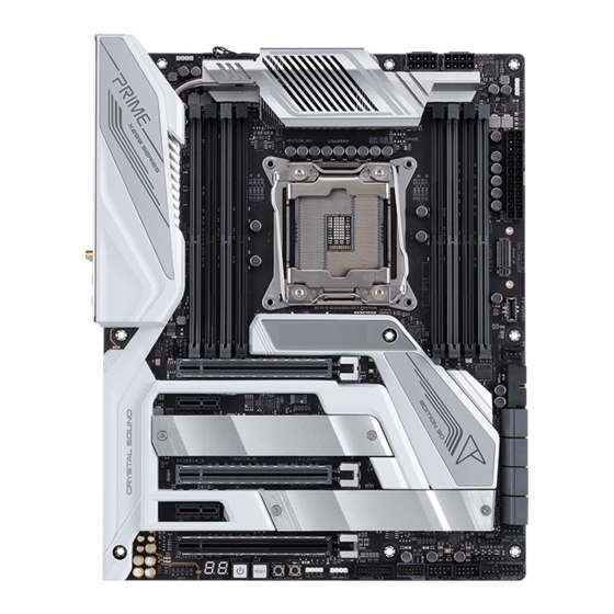
Page 20: Motherboard Layout
Motherboard layout Refer to Internal connectors and Rear I/O connection for more information about rear panel connectors and internal connectors. Chapter 1: Product Introduction... - Page 21 15. Thermal sensor connector 1-17 16. Node connector 1-25 17. AURA RGB LED connector 1-23 18. BIOS FlashBack™ button 2-15 19. Clear CMOS button 1-10 20. FlexKey button (Reset) 21. Power button 22. Q-Code LED 1-13 23. Front panel audio connector 1-15 24. OLED connector 1-26 ASUS PRIME X299 EDITION 30...
-
Page 22: Central Processing Unit (Cpu)
Core™ X-series Processors. • Ensure that you install the correct CPU designed for LGA2066 socket only. DO NOT install a CPU designed for other sockets on the LGA2066 socket. • The CPU fits in only one correct orientation. DO NOT force the CPU into the socket to prevent bending the connectors on the socket and damaging the CPU. • Ensure that all power cables are unplugged before installing the CPU. • Upon purchase of the motherboard, ensure that the PnP cap is on the socket and the socket contacts are not bent. Contact your retailer immediately if the PnP cap is missing, or if you see any damage to the PnP cap/socket contacts/motherboard components. ASUS will shoulder the cost of repair only if the damage is shipment/ transit-related. • Keep the cap after installing the motherboard. ASUS will process Return Merchandise Authorization (RMA) requests only if the motherboard comes with the cap on the LGA2066 socket. • The product warranty does not cover damage to the socket contacts resulting from incorrect CPU installation/removal, or misplacement/loss/incorrect removal of the PnP cap. Chapter 1: Product Introduction... -
Page 23: System Memory
System memory The motherboard comes with Dual Inline Memory Modules (DIMM) slots designed for DDR4 (Double Data Rate 4) memory modules. A DDR4 memory module is notched differently from a DDR, DDR2, or DDR3 module. DO NOT install a DDR, DDR2, or DDR3 memory module to the DDR4 slot. Recommended memory configurations Intel Core™ X-series Processors ® ASUS PRIME X299 EDITION 30... -
Page 24: Memory Configurations
Memory configurations You may install 4 GB, 8 GB, 16 GB and 32 GB unbuffered and non-ECC DDR4 DIMMs into the DIMM sockets. For Intel Core™ X-Series Processors (6-core or above), you may install varying memory ® sizes in Channel A, Channel B, Channel C, and Channel D. The system maps the total size of the lower-sized channel for the quad-channel configuration. Any excess memory from the higher-sized channel is then mapped for single-channel operation. • The default memory operation frequency is dependent on its Serial Presence Detect (SPD), which is the standard way of accessing information from a memory module. Under the default state, some memory modules for overclocking may operate at a lower frequency than the vendor-marked value. • For system stability, use a more efficient memory cooling system to support a full memory load or overclocking condition. • Always install the DIMMS with the same CAS Latency. For an optimum compatibility, we recommend that you install memory modules of the same version or data code (D/C) from the same vendor. Check with the vendor to get the correct memory modules. • Visit the ASUS website for the latest QVL. Chapter 1: Product Introduction... -
Page 25: Expansion Slots
Expansion slots Unplug the power cord before adding or removing expansion cards. Failure to do so may cause you physical injury and damage motherboard components. ASUS PRIME X299 EDITION 30... - Page 26 Recommended VGA configuration 48 and 44-Lane CPUs Slot Description Single VGA Dual VGA Triple VGA PCIEX16_1 X16 PCIEX1_1 PCIEX16_2 PCIEX1_2 PCIEX16_3 28-Lane CPUs Slot Description Single VGA Dual VGA PCIEX16_1 X16 PCIEX1_1 PCIEX16_2 PCIEX1_2 PCIEX16_3 • We recommend that you provide sufficient power when running CrossFireX™ or SLI ® mode. • Ensure to connect the dual 8-pin power plugs when running CrossFireX™ or SLI ®...
-
Page 27: Onboard Buttons
The button also lights up when the system is plugged to a power source, indicating that you should shut down the system and unplug the power cable before removing or installing any motherboard component. FlexKey button (Reset) Press the FlexKey button to reboot the system. You may also configure the button and assign a quick access feature such as activating Safe Boot or turning Aura lighting on or off to the button. This button set to [Reset] by default. You can assign a different function to this button in the BIOS settings. ASUS PRIME X299 EDITION 30... - Page 28 Clear CMOS button Press the Clear CMOS button to clear the Real Time Clock (RTC) RAM in the CMOS, which contains the date, time, system passwords, and system setup parameters. To erase the RTC RAM: Turn OFF the computer and unplug the power cord. Press the button for about 5 to 10 seconds. Plug the power cord and turn ON the computer. Hold down the <Del> key during the boot process and enter BIOS setup to re-enter data. 1-10 Chapter 1: Product Introduction...
-
Page 29: Onboard Jumpers
Onboard Jumpers CPU Over Voltage jumper The CPU Over Voltage jumper allows you to set a higher CPU voltage for a flexible overclocking system (depending on the type of the installed CPU). Set to pins 2-3 to increase the CPU voltage setting, or set to pins 1-2 to use the default CPU voltage setting. ASUS PRIME X299 EDITION 30 1-11... -
Page 30: Onboard Leds
Onboard LEDs Q LEDs The Q LEDs check key components (CPU, DRAM, VGA, and booting devices) during the motherboard booting process. If an error is found, the critical component’s LED stays lit up until the problem is solved. The Q LEDs provide the most probable cause of an error code as a starting point for troubleshooting. The actual cause may vary from case to case. USB BIOS FlashBack ™ The BIOS FlashBack LED flashes when you press the BIOS FlashBack button for ™ ™ BIOS update. 1-12 Chapter 1: Product Introduction... - Page 31 Q-Code LED The Q-Code LED design provides you with a 2-digit error code that displays the system status. • The Q-Code LEDs provide the most probable cause of an error code as a starting point for troubleshooting. The actual cause may vary from case to case. • Please refer to the Q-Code table in the Appendix section for more details. ASUS PRIME X299 EDITION 30 1-13...
-
Page 32: Internal Connectors
Internal connectors SATA 6 Gb/s connectors The SATA 6Gb/s connector allows you to connect SATA devices such as optical disc drives and hard disk drives via a SATA cable. If you installed SATA storage devices, you can create a RAID 0, 1, 5, and 10 configuration with the Intel Rapid Storage Technology through the onboard Intel X299 chipset. ® ® • The connectors are set to [IRST Mode] by default. • When using the M.2_2 socket with SATA bandwidth, the SATA6G_1 connector will be disabled. Before creating a RAID set, refer to the RAID Configuration Guide. You can • download the RAID Configuration Guide from the ASUS website. 1-14 Chapter 1: Product Introduction... - Page 33 Front panel audio connector The front panel audio connector is for a chassis-mounted front panel audio I/O module that supports HD Audio. Connect one end of the front panel audio I/O module cable to this connector. We recommend that you connect a high-definition front panel audio module to this connector to avail of the motherboard’s high-definition audio capability. USB 3.2 Gen 2 connector The USB 3.2 Gen 2 connector allows you to connect a USB 3.2 Gen 2 module for additional USB 3.2 Gen 2 ports. The USB 3.2 Gen 2 connector provides data transfer speeds of up to 10 Gb/s. The USB 3.2 Gen 2 module is purchased separately. ASUS PRIME X299 EDITION 30 1-15...
- Page 34 USB 3.2 Gen 1 connector The USB 3.2 Gen 1 connector allows you to connect a USB 3.2 Gen 1 module for additional USB 3.2 Gen 1 ports. The USB 3.2 Gen 1 connector provides data transfer speeds of up to 5 Gb/s. The USB 3.2 Gen 1 module is purchased separately. 1-16 Chapter 1: Product Introduction...
- Page 35 USB 2.0 connector The USB 2.0 connector allows you to connect a USB module for additional USB 2.0 ports. The USB 2.0 connector provides data transfer speeds of up to 480 MB/s connection speed. DO NOT connect a 1394 cable to the USB connectors. Doing so will damage the motherboard! The USB 2.0 module is purchased separately. Thermal Sensor connector The Thermal Sensor connector allows you to connect a sensor to monitor the temperature of the devices and the critical components inside the motherboard. Connect the thermal sensor and place it on the device or the motherboard’s component to detect its temperature. ASUS PRIME X299 EDITION 30 1-17...
- Page 36 Fan and Pump connectors The Fan and Pump connectors allow you to connect fans or pumps to cool the system. • DO NOT forget to connect the fan cables to the fan connectors. Insufficient air flow inside the system may damage the motherboard components. These are not jumpers! Do not place jumper caps on the fan connectors! •...
-
Page 37: Power Connectors
Power connectors These Power connectors allow you to connect your motherboard to a power supply. The power supply plugs are designed to fit in only one orientation, find the proper orientation and push down firmly until the power supply plugs are fully inserted. DO NOT connect the 8-pin power plug only, the motherboard may overheat under heavy usage. • We recommend that you use a PSU with a higher power output when configuring a system with more power-consuming devices. The system may become unstable or may not boot up if the power is inadequate. • If you want to use two or more high-end PCIe x16 cards, use a PSU with 1000W power or above to ensure the system stability. ASUS PRIME X299 EDITION 30 1-19... - Page 38 System Panel connector The System Panel connector supports several chassis-mounted functions. • System Warning Speaker connector (SPEAKER) The 4-pin connector allows you to connect the chassis-mounted system warning speaker. The speaker allows you to hear system beeps and warnings. • System Power LED connector (PLED) The 2-pin connector allows you to connect the System Power LED. The System Power LED lights up when the system is connected to a power source, or when you turn on the system power, and blinks when the system is in sleep mode.
- Page 39 2280 / 22110 PCIe storage devices. • For Intel X299 Chipset supports with Intel Rapid Storage Technology (RAID 0, ® ® 1, 5, 10): - M .2_2 socket supports PCIe 3.0 x4 mode and SATA mode vertical M Key design and type 2242 / 2260 / 2280 / 22110 PCIe and SATA storage devices. The M.2_2 socket shares bandwidth with SATA6G_1 port when using M.2 SATA devices. - M .2_1 socket supports PCIe 3.0 x4 mode M Key design and type 2242 / 2260 / 2280 / 22110 PCIe storage devices. The M.2_1 PCIe mode source is from X299 Chipset when using 44 and 28-lane CPU. • The M.2 PCIe mode source from X299 Chipset supports Intel Optane Memory. ® The M.2 SSD module is purchased separately. ASUS PRIME X299 EDITION 30 1-21...
- Page 40 Cover LED connector The Cover LED connector is for connecting the LED strips on your motherboard cover. 1-22 Chapter 1: Product Introduction...
- Page 41 AURA RGB LED connector The AURA RGB LED connector allows you to connect RGB LED strips. The AURA RGB LED connector supports 5050 RGB multi-color LED strips (12V/G/R/B), with a maximum power rating of 3A (12V), and no longer than 3m. Before you install or remove any component, ensure that the power supply is switched off or the power cord is detached from the power supply. Failure to do so may cause severe damage to the motherboard, peripherals, or components. • Actual lighting and color will vary with LED strip. • If your LED strip does not light up, check if the RGB LED extension cable and the RGB LED strip is connected in the correct orientation, and the 12V connector is aligned with the 12V header on the motherboard. • The LED strip will only light up when the system is powered on. • The LED strip is purchased separately. ASUS PRIME X299 EDITION 30 1-23...
- Page 42 Addressable Gen 2 LED connector The Addressable Gen 2 LED connector allows you to connect individually addressable RGB WS2812B LED strips or WS2812B based LED strips. The Addressable Gen 2 LED connector supports WS2812B addressable RGB LED strips (5V/Data/Ground), with a maximum power rating of 3A (5V) and a maximum of 120 LEDs. Before you install or remove any component, ensure that the power supply is switched off or the power cord is detached from the power supply. Failure to do so may cause severe damage to the motherboard, peripherals, or components. • Actual lighting and color will vary with LED strip. • If your LED strip does not light up, check if the addressable RGB LED strip is connected in the correct orientation, and the 5V connector is aligned with the 5V header on the motherboard. • The addressable RGB LED strip will only light up when the system is powered on. • The addressable RGB LED strip is purchased separately. 1-24 Chapter 1: Product Introduction...
- Page 43 VROC Key connector The VROC (Virtual Raid on CPU) Key connector allows you to connect a VROC hardware key to enable additional CPU RAID functions with Intel CPU RSTe. ® The VROC hardware key is purchased separately. Node connector The Node connector allows you to connect Node compatible devices. Visit www.asus.com for more information about the devices and the latest compatibility list. ASUS PRIME X299 EDITION 30 1-25...
- Page 44 OLED connector The OLED connector allows you to connect the LiveDash OLED panel. The OLED panel provides you a quick overview of the system temperature, power status, and fan speeds when your system boots up. • Use the LiveDash Utility in Armoury Crate to configure and customize the LiveDash OLED panel. • The LiveDash OLED displays a Q-Code that provides the most probable cause of an error code as a starting point for troubleshooting. The actual cause may vary from case to case. • Please refer to the Q-Code table in the Appendix section for more details. 1-26 Chapter 1: Product Introduction...
-
Page 45: Chapter 2: Basic Installation
Chapter 2: Basic Installation Basic Installation Building your PC system The diagrams in this section are for reference only. The motherboard layout may vary with models, but the installation steps are the same for all models. 2.1.1 CPU installation • Ensure that you install the correct CPU designed for LGA2066 socket only. • ASUS will not cover damages resulting from incorrect CPU installation/removal, incorrect CPU orientation/placement, or other damages resulting from negligence by the user. • Please note the order in opening/ closing the double latch. Follow the instructions printed on the metal sealing hatch or the illustrations shown below in this manual. The plastic cap will pop up automatically once the CPU is in place and the hatch properly sealed down. ASUS PRIME X299 EDITION 30... - Page 46 Triangle mark Triangle mark Chapter 2: Basic Installation...
- Page 47 ASUS PRIME X299 EDITION 30...
-
Page 48: Cooling System Installation
2.1.2 Cooling system installation Apply the Thermal Interface Material to the CPU heatsink and CPU before you install the heatsink and fan, if necessary. To install the CPU heatsink and fan assembly Chapter 2: Basic Installation... - Page 49 To install an AIO cooler AIO_PUMP CPU_FAN CPU_OPT ASUS PRIME X299 EDITION 30...
-
Page 50: Motherboard Installation
2.1.3 Motherboard installation Place the motherboard into the chassis, ensuring that its rear I/O ports are aligned to the chassis’ rear I/O panel. Place nine (9) screws into the holes indicated by circles to secure the motherboard to the chassis. DO NOT over tighten the screws! Doing so can damage the motherboard. Chapter 2: Basic Installation... -
Page 51: Dimm Installation
2.1.4 DIMM installation To remove a DIMM ASUS PRIME X299 EDITION 30... -
Page 52: Atx Power Connection
2.1.5 ATX power connection Ensure to connect the 8-pin power plug. Chapter 2: Basic Installation... -
Page 53: Sata Device Connection
2.1.6 SATA device connection ASUS PRIME X299 EDITION 30... -
Page 54: Front I/O Connector
2.1.7 Front I/O connector To install USB 3.2 Gen 2 connector To install ASUS Q-Connector USB 3.2 Gen 2 This connector will only fit in one orientation. Push the connector until it clicks into place. To install USB 3.2 Gen 1 connector To install USB 2.0 connector USB 3.2 Gen 1 USB 2.0... -
Page 55: Expansion Card Installation
2.1.8 Expansion card installation To install PCIe x16 cards To install PCIe x1 cards ASUS PRIME X299 EDITION 30 2-11... - Page 56 To install FAN EXTENSION CARD II The illustrations in this section are for reference only. The chassis and motherboard layout may vary with models, but the installation steps are the same for all models. 2-12 Chapter 2: Basic Installation...
-
Page 57: M.2 Installation
2.1.9 M.2 installation The M.2 is purchased separately. ASUS PRIME X299 EDITION 30 2-13... -
Page 58: Wi-Fi Antenna Installation
2.1.10 Wi-Fi antenna installation Installing the ASUS 2x2 dual band W-Fi antenna Connect the bundled ASUS 2x2 dual band Wi-Fi antenna connector to the Wi-Fi ports at the back of the chassis. • Ensure that the ASUS 2x2 dual band Wi-Fi antenna is securely installed to the Wi-Fi ports. • Ensure that the antenna is at least 20 cm away from all persons. The illustration above is for reference only. The I/O port layout may vary with models, but the Wi-Fi antenna installation procedure is the same for all models. 2-14 Chapter 2: Basic Installation... -
Page 59: Thunderbolt™ 3 Monitor Connection
2.1.11 Thunderbolt™ 3 monitor connection Connect the bundled ASUS DisplayPort cable to the DisplayPort on a discrete graphic card and to the DisplayPort IN port on the motherboard. Refer to section Rear I/O connection for the location of the DisplayPort IN port. DisplayPort IN DisplayPort Connect the Thunderbolt™ 3 cable to the Thunderbolt™ 3 Type-C™ port on the motherboard and to the Thunderbolt™ 3 Type-C™ port on a monitor. • The Thunderbolt™ 3 cable is not bundled with the motherboard package. Use the Thunderbolt™ cable that came with your Thunderbolt-enabled device when connecting to the Thunderbolt™ 3 Type-C™ port on your motherboard. • You can connect a USB Type-C™ to Thunderbolt™ adapter, then connect the Thunderbolt™ cable from your Thunderbolt-enabled device to the Thunderbolt™ 3 Type-C™ port on the motherboard. • Thunderbolt™ 3 Type-C™ port is backward compatible with the previous Thunderbolt™ technology. ASUS PRIME X299 EDITION 30 2-15... -
Page 60: Bios Update Utility
™ BIOS or operating system. Simply insert a USB storage device to the USB port, press the USB BIOS FlashBack button for three seconds, and the BIOS is updated automatically. ™ To use USB BIOS FlashBack ™ Insert a USB storage device to the USB FlashBack port. ™ We recommend you to use a USB storage device to save the latest BIOS version for better compatibility and stability. USB BIOS FlashBack port ™ Visit https://www.asus.com/support/ and download the latest BIOS version for this motherboard. Rename the file as X299E3.CAP, then copy it to your USB storage device. Shut down your computer. On your motherboard, press the BIOS FlashBack button for three seconds until the ™ FlashBack LED blinks three times, indicating that the BIOS FlashBack function is ™ ™ enabled. Wait until the light goes out, indicating that the BIOS updating process is completed. 2-16 Chapter 2: Basic Installation... - Page 61 • Refer to section Onboard LEDs for more information of the FlashBack LED. ™ For more BIOS update utilities in BIOS setup, refer to the section Updating BIOS in • Chapter 3. • Do not unplug portable disk, power system, or press the CLR_CMOS button while BIOS update is ongoing, otherwise update will be interrupted. In case of interruption, please follow the steps again. • If the light flashes for five seconds and turns into a solid light, this means that the BIOS FlashBack is not operating properly. This may be caused by improper ™ installation of the USB storage device and filename/file format error. If this scenario happens, please restart the system to turn off the light. • Updating BIOS may have risks. If the BIOS program is damaged during the process and results to the system’s failure to boot up, please contact your local ASUS Service Center. ASUS PRIME X299 EDITION 30 2-17...
-
Page 62: Motherboard Rear And Audio Connections
Motherboard rear and audio connections 2.3.1 Rear I/O connection Rear panel connectors Intel Gb LAN port (LAN1)* USB 3.2 Gen 1 ports E23 ® Aquantia 5G LAN port (LAN2)* DisplayPort IN 2 for Thunderbolt™ 3 ® DisplayPort IN 1 for Thunderbolt™ 3 Thunderbolt™ 3 Type-C™ port EC1 USB 3.2 Gen 1 port E1 Thunderbolt™ 3 Type-C™ port EC2 USB 3.2 Gen 1 port 5 Optical S/PDIF OUT port Intel Wi-Fi 6 AX200, Bluetooth V5.0 ® Audio I/O ports** ports USB 2.0 ports 11 and 12 (bottom port supports USB BIOS FlashBack ™ * and ** : Refer to the tables on the next page for LAN port LEDs, and audio port definitions. •... - Page 63 ** Audio 2, 4, 5.1 or 7.1-channel configuration Headset Port 4-channel 5.1-channel 7.1-channel 2-channel Light Blue Line In Line In Line In Side Speaker Out Lime Line Out Front Speaker Out Front Speaker Out Front Speaker Out Pink Mic In Mic In Mic In Mic In Orange – – Center/Sub Center/Sub woofer woofer Black – Rear Speaker Out Rear Speaker Out Rear Speaker Out ASUS PRIME X299 EDITION 30 2-19...
-
Page 64: Audio I/O Connections
2.3.2 Audio I/O connections Audio I/O ports Connect to Headphone and Mic Connect to Stereo Speakers Connect to 2-channel Speakers 2-20 Chapter 2: Basic Installation... - Page 65 Connect to 4-channel Speakers Connect to 5.1-channel Speakers Connect to 7.1-channel Speakers ASUS PRIME X299 EDITION 30 2-21...
-
Page 66: Starting Up For The First Time
Starting up for the first time After making all the connections, replace the system case cover. Ensure that all switches are off. Connect the power cord to the power connector at the back of the system chassis. Connect the power cord to a power outlet that is equipped with a surge protector. Turn on the devices in the following order: a. Monitor b. External SCSI devices (starting with the last device on the chain) System power After applying power, the system power LED on the system front panel case lights up. For systems with ATX power supplies, the system LED lights up when you press the ATX power button. If your monitor complies with the “green” standards or if it has a “power standby” feature, the monitor LED may light up or change from orange to green after the system LED turns on. The system then runs the power-on self tests (POST). While the tests are running, the BIOS beeps (refer to the BIOS beep codes table) or additional messages appear on the screen. If you do not see anything within 30 seconds from the time you turned on the power, the system may have failed a power-on test. Check the jumper settings and connections or call your retailer for assistance. BIOS Beep Description VGA detected One short beep Quick boot set to disabled No keyboard detected One continuous beep followed by two No memory detected short beeps then a pause (repeated) One continuous beep followed by three No VGA detected short beeps One continuous beep followed by four Hardware component failure short beeps At power on, hold down the <Delete> key to enter the BIOS Setup. Follow the... -
Page 67: Chapter 3: Bios Setup
BIOS Setup Knowing BIOS The new ASUS UEFI BIOS is a Unified Extensible Interface that complies with UEFI architecture, offering a user-friendly interface that goes beyond the traditional keyboard- only BIOS controls to enable a more flexible and convenient mouse input. You can easily navigate the new UEFI BIOS with the same smoothness as your operating system. -
Page 68: Bios Setup Program
RTC RAM via the Clear CMOS button. • The BIOS setup program does not support the Bluetooth devices. Please visit ASUS website for the detailed BIOS content manual. BIOS menu screen The BIOS Setup program can be used under two modes: EZ Mode and Advanced Mode. -
Page 69: Ez Mode
Click to go to Advanced mode Loads optimized Search on the FAQ default settings Click to display boot devices Selects the boot device priority The boot device options vary depending on the devices you installed to the system. ASUS PRIME X299 EDITION 30... -
Page 70: Advanced Mode
3.2.2 Advanced Mode The Advanced Mode provides advanced options for experienced end-users to configure the BIOS settings. The figure below shows an example of the Advanced Mode. Refer to the following sections for the detailed configurations. To switch from EZ Mode to Advanced Mode, click Advanced Mode(F7) or press the <F7> hotkey. -
Page 71: Menu Bar
This button above the menu bar allows you to view the descriptions of AI overclocking and enable it. Refer to section AI OC Guide for more information. • • This function is only enabled when using an unlocked CPU. ASUS PRIME X299 EDITION 30... -
Page 72: Scroll Bar
Move your mouse over this button to show a QR code, scan this QR code on your mobile device to connect to the BIOS FAQ web page of the ASUS support website. You can also scan the following QR code:... - Page 73 This button allows you to view and configure the RAID settings of your system. Refer to section EZ Tuning Wizard for more information. Last Modified button This button shows the items that you last modified and saved in BIOS Setup. ASUS PRIME X299 EDITION 30...
-
Page 74: Qfan Control
3.2.3 QFan Control The QFan Control allows you to set a fan profile or manually configure the operating speed of your CPU and chassis fans. Click to select a fan to be Click to activate DC Mode configured Select a profile to apply to Click to apply the fan setting your fans Click to undo the... - Page 75 Select the fan that you want to configure and to view its current status. Click and drag the speed points to adjust the fans’ operating speed. Click Apply to save the changes then click Exit (ESC). ASUS PRIME X299 EDITION 30...
-
Page 76: Ai Oc Guide
3.2.4 AI OC Guide • The screenshot shown in this section is for reference purposes only, and may not exactly match what you see on your screen. • This function is only enabled when using an unlocked CPU. The AI OC Guide allows you to enable the Ai Overclocking feature, or view a quick guide of the Ai Overclocking feature which highlights the recommended setup procedure and descriptions of the AI Overclocking. -
Page 77: Ez Tuning Wizard
Click RAID then select the port that you want to set to [RAID] mode, CPU, PCH or SATA, then click Next. • Ensure that your HDDs have no existing RAID volumes. • Ensure to connect your HDDs to Intel SATA connectors. ® Select OK to enable RAID. ASUS PRIME X299 EDITION 30 3-11... - Page 78 Select the type of storage for your RAID, Easy Backup or Super Speed, then click Next. For Easy Backup, click Next then select from Easy Backup (RAID 1) or Easy Backup (RAID 10). You can only select Easy Backup (RAID 10) if you connect four (4) HDDs. For Super Speed, click Next then select from Super Speed (RAID 0) or Super Speed (RAID 5).
-
Page 79: My Favorites
My Favorites is your personal space where you can easily save and access your favorite BIOS items. My Favorites comes with several performance, power saving, and fast boot related items by default. You can personalize this screen by adding or removing items. ASUS PRIME X299 EDITION 30 3-13... - Page 80 Adding items to My Favorites To add BIOS items: Press <F3> on your keyboard or click MyFavorite(F3) from the BIOS screen to open Setup Tree Map screen. On the Setup Tree Map screen, select the BIOS items that you want to save in My Favorites screen.
-
Page 81: Main Menu
This item allows you to set the BCLK (base clock) frequency to enhance the system performance. Use the <+> or <-> to adjust the value. We recommend you to set the value based on the CPU specification, as high BCLK frequencies may damage the CPU permanently. ASUS PRIME X299 EDITION 30 3-15... - Page 82 ASUS MultiCore Enhancement [Auto] This item allows you to maximize the oveclocking performance optimized by ASUS core ratio settings. [Disabled] This item allows you to set to default core ratio settings. CPU Core Ratio This item allows you to set the CPU core ratios.
-
Page 83: Advanced Menu
The items in this menu allow you to change the ASPM for PCH and SA PCIe. 3.6.3 System Agent (SA) Configuration The items in this menu allow you to adjust the Link Speed for PEG Port and Multi-Monitor. ASUS PRIME X299 EDITION 30 3-17... -
Page 84: Pch Configuration
3.6.4 PCH Configuration The items in this menu allow you to adjust the PCH PCIe speed. PCI Express Configuration This item allows you to configure the PCIe slots. PCIe Speed This item allows your system to automatically select the PCIe port speed. Configuration options: [Auto] [Gen1 (2.5 GT/s)] [Gen2 (5 GT/s)] [Gen3 (8 GT/s)] 3.6.5 PCH Storage Configuration... -
Page 85: Cpu Storage Configuration
This item allows you to enable or disable the Intel Bluetooth controller. Configuration options: [Disabled] [Enabled] Intel LAN Controller / 5G LAN Card This item allows you to enable or disable the Intel LAN controller / 5G LAN Card. Configuration options: [Disabled] [Enabled] ASUS PRIME X299 EDITION 30 3-19... -
Page 86: Apm Configuration
3.6.8 APM Configuration The items in this menu allow you to set system wake and sleep settings. ErP Ready [Disabled] This item allows you to switch off some power at S4+S5 or S5 to get the system ready for ErP requirement. When set to [Enabled], all other PME options are switched off. Configuration options: [Disabled] [Enable(S4+S5)] [Enable(S5)] 3.6.9 Network Stack Configuration... -
Page 87: Thunderbolt(Tm) Configuration
Next Boot after AC Power Loss [Normal Boot] Returns to normal boot on the next boot after an AC power loss. [Fast Boot] Accelerates the boot speed on the next boot after an AC power loss. ASUS PRIME X299 EDITION 30 3-21... -
Page 88: Boot Configuration
Boot Configuration Setup Mode [Advanced Mode] This item allows you to go to Advanced Mode of the BIOS after POST. [EZ Mode] This item allows you to go to EZ Mode of the BIOS after POST. CSM (Compatibility Support Module) This item allows you to configure the CSM (Compatibility Support Module) items to fully support the various VGA, bootable devices and add-on devices for better compatibility. -
Page 89: Tool Menu
3.9.1 ASUS EZ Flash 3 Utility This item allows you to run ASUS EZ Flash 3. When you press <Enter>, a confirmation message appears. Use the left/right arrow key to select between [Yes] or [No], then press <Enter> to confirm your choice. -
Page 90: Secure Erase
To launch Secure Erase, click Tool > Secure Erase on the Advanced mode menu. Check the ASUS support site for a full list of SSDs tested with Secure Erase. The drive may become unstable if you run Secure Erase on an incompatible SSD. -
Page 91: Asus Spd Information
This item displays the information and recommended configuration for the PCIe slots that the graphics card is installed in your system. This feature is only supported on selected ASUS graphics cards. Bus Interface This item allows you to select the bus interface. -
Page 92: Exit Menu
3.10 Exit menu The Exit menu items allow you to load the optimal default values for the BIOS items, and save or discard your changes to the BIOS items. You can access the EZ Mode from the Exit menu. Load Optimized Defaults This option allows you to load the default values for each of the parameters on the Setup menus. -
Page 93: Updating Bios
® ASUS EZ Flash 3: Updates the BIOS using a USB flash drive. ASUS CrashFree BIOS 3: Restores the BIOS using the motherboard support DVD or a USB flash drive when the BIOS file fails or gets corrupted. 3.11.1... -
Page 94: Asus Ez Flash 3
3.11.2 ASUS EZ Flash 3 ASUS EZ Flash 3 allows you to download and update to the latest BIOS through the Internet without having to use a bootable floppy disk or an OS-based utility. Updating through the Internet varies per region and Internet conditions. Check your local Internet connection before updating through the Internet. - Page 95 To update the BIOS by Internet: Enter the Advanced Mode of the BIOS setup program. Go to the Tool menu to select ASUS EZ Flash Utility and press <Enter>. Select by Internet. Press the Left/Right arrow keys to select an Internet connection method, and then press <Enter>.
-
Page 96: Asus Crashfree Bios 3
The BIOS file in the motherboard support DVD may be older than the BIOS file published on the ASUS official website. If you want to use the newer BIOS file, download the file at https://www.asus.com/support/ and save it to a USB flash drive. -
Page 97: Chapter 4: Raid Support
® RAID 1, RAID 5 and RAID 10 configuration. For more information on configuring your RAID sets, please refer to the RAID Configuration Guide which you can find at https://www.asus.com/support. 4.1.1 RAID definitions RAID 0 (Data striping) optimizes two identical hard disk drives to read and write data in parallel, interleaved stacks. - Page 98 Chapter 4: RAID Support...
-
Page 99: Appendix
CPU self test failed or possible CPU cache error CPU micro-code is not found or micro-code update is failed Internal CPU error Reset PPI is not available 5C – 5F Reserved for future AMI error codes (continued on the next page) ASUS PRIME X299 EDITION 30... -
Page 100: Q-Code Table
Q-Code table Code Description S3 Resume is stared (S3 Resume PPI is called by the DXE IPL) S3 Boot Script execution Video repost OS S3 wake vector call E4 – E7 Reserved for future AMI progress codes S3 Resume Failed S3 Resume PPI not Found S3 Resume Boot Script Error S3 OS Wake Error... - Page 101 Reserved for ASL (see ASL Status Codes section below) Ready To Boot event Legacy Boot event Exit Boot Services event Runtime Set Virtual Address MAP Begin Runtime Set Virtual Address MAP End Legacy Option ROM Initialization System Reset (continued on the next page) ASUS PRIME X299 EDITION 30...
- Page 102 Q-Code table Code Description USB hot plug PCI bus hot plug Clean-up of NVRAM Configuration Reset (reset of NVRAM settings) B8– BF Reserved for future AMI codes CPU initialization error System Agent initialization error PCH initialization error Some of the Architectural Protocols are not available PCI resource allocation error.
-
Page 103: Notices
20 cm from all persons and must not be co-located or operating in conjunction with any other antenna or transmitter. End-users and installers must be provide with antenna installation instructions and transmitter operating conditions for satisfying RF exposure compliance. ASUS PRIME X299 EDITION 30... - Page 104 Compliance Statement of Innovation, Science and Economic Development Canada (ISED) This device complies with Innovation, Science and Economic Development Canada licence exempt RSS standard(s). Operation is subject to the following two conditions: (1) this device may not cause interference, and (2) this device must accept any interference, including interference that may cause undesired operation of the device.
- Page 105 ASUS products sold in Vietnam, on or after September 23, 2011,meet the requirements of the Vietnam Circular 30/2011/TT-BCT. Các sản phẩm ASUS bán tại Việt Nam, vào ngày 23 tháng 9 năm2011 trở về sau, đều phải đáp ứng các yêu cầu của Thông tư 30/2011/TT-BCT của Việt Nam.
- Page 106 DO NOT throw the motherboard in municipal waste. This product has been designed to enable proper reuse of parts and recycling. This symbol of the crossed out wheeled bin indicates that the product (electrical and electronic equipment) should not be placed in municipal waste.
- Page 107 Tenez cet appareil à distance du ventre des femmes enceintes et du bas-ventre des adolescents. ASUS PRIME X299 EDITION 30...
- Page 108 2014/53/EU. Cijeli pada Petunjuk 2014/53/EU. Teks lengkap pernyataan kesesuaian EU tersedia tekst EU izjave o sukladnosti dostupan je na https://www.asus.com/support/ di: https://www.asus.com/support/ WiFi koji radi na opsegu frekvencija 5150-5350 MHz bit će ograničen na...
- Page 109 ASUSTek Computer Inc. tukaj izjavlja, da je ta naprava skladna s temeljnimi zahtevami in drugimi relevantnimii določili Direktive 2014/53/EU. Polno besedilo izjave EU o skladnosti je na voljo na https://www.asus.com/ support/ WiFi, ki deluje v pasovnem območju 5150–5350 MHz, mora biti v državah, navedenih v spodnjem seznamu, omejen na notranjo uporabo: Declaración de conformidad simplificada para la UE...
-
Page 110: Asus Contact Information
+1-510-739-3777 +1-510-608-4555 Web site http://www.asus.com/us/ Technical Support Support fax +1-812-284-0883 Telephone +1-812-282-2787 Online support http://qr.asus.com/techserv ASUS COMPUTER GmbH (Germany and Austria) Address Harkort Str. 21-23, 40880 Ratingen, Germany +49-2102-959931 Web site http://www.asus.com/de Online contact http://eu-rma.asus.com/sales Technical Support Telephone +49-2102-5789555 Support Fax...