Table of Contents
Advertisement
Quick Links
SPECIFICATIONS
2004 Matsushita Electric Industrial Co. Ltd.. All rights reserved.
PDF created with pdfFactory Pro trial version
Specification
Type
Speaker unit(s)
1. Woofer
2. Woofer
3. Tweeter
Input power (IEC)
Output sound pressure
Cross over frequency
Frequency range
Dimensions (W x H x D)
Mass
Notes :
1. Specifications are subject to change without notice.
2. Mass and dimensions are approximate.
SB-HT930P-S consists of : SB-FS930P-S (x 2), SB-FS931P-S (x
2)
and SB-PC930P-S (x 1)
www.pdffactory.com
ORDER NO. MD0412609C0
2 way, 3 speaker system (Bass
reflex)
Impedance 4
6.5 cm (2-1/2") Cone type
6.5 cm (2-1/2") Cone type
6 cm (2-3/8") Ring shaped dome
260 W* (Max)
82 dB/W (1.0 m)
5 kHz
110 Hz - 50 kHz (-16 dB)
140 Hz - 45 kHz (-10 dB)
320 mm x 88 mm x 96 mm
(12-19/32" x 3-15/32" x 3-25/32")
1.36 kg (3 lbs)
1
A6
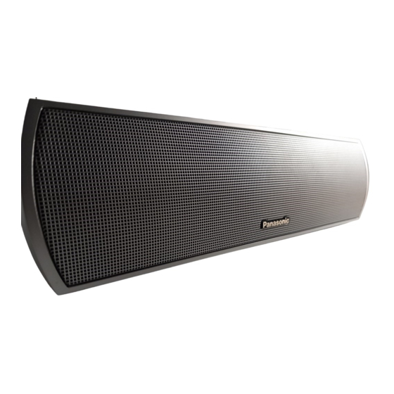
Speaker System
SB-PC930P
Colour
(S)... Silver Type
type
Advertisement
Table of Contents

Related Manuals for Panasonic SB-PC930P


Summary of Contents for Panasonic SB-PC930P
- Page 1 1. Specifications are subject to change without notice. 2. Mass and dimensions are approximate. SB-HT930P-S consists of : SB-FS930P-S (x 2), SB-FS931P-S (x and SB-PC930P-S (x 1) 2004 Matsushita Electric Industrial Co. Ltd.. All rights reserved. PDF created with pdfFactory Pro trial version...
-
Page 2: System Combination
Unauthorized copying and distribution is a violation of law. 1. System Combination System SC-HT930P-S SC-HT930PC-S Music Center SA-HT930P-S SA-HT930PC-S Front Speakers SB-FS930P-S Surround Speakers SB-FS931P-S Centre Speaker SB-PC930P-S Active Subwoofer SB-WA930PP-S System SC-HT930PX-S Music Center SA-HT930PX-S Front Speakers SB-FS930P-S Surround Speakers SB-FS931P-S Centre Speaker SB-PC930P-S Active Subwoofer... -
Page 3: Disassembly Process
System SC-HT930GC-S SC- SC-HT930GS-S HT930GCSS Music Center SA-HT930GC-S SA- SA-HT930GS-S HT930GCSS Front Speakers SB-FS930P-S Surround SB-FS880EB-S Speakers Centre Speaker SB-PC930P-S Active SB-WA930GC-S Subwoofer System SC-HT880EB-S SC-HT880WEBS Music Center SA-HT880EB-S SA-HT880WEBS Front Speakers SB-FS930P-S Surround Speakers SB-FS880EB-S Centre Speaker SB-PC930P-S Active Subwoofer... - Page 4 Step 1: Remove 8 screws from the Rear Cabinet Assembly. Step 2: Push the Front Panel forward to detach from the Rear Cabinet Assembly as arrow shown above. 2.2. Disassembly of the Woofer 1 - Repeat step 1 to step 2 in item 2.1. Step 1: Detach the wires (+) red and (-) black from the Woofer 1.
- Page 5 Step 2: Remove 4 screws from the Woofer 1. 2.3. Disassembly of the Woofer 2 - Repeat step 1 to step 2 in item 2.1. Step 1: Detach the wires (+) black and (-) black from the Woofer 2. Step 2: Remove 4 screws from the Woofer 2. 2.4.
- Page 6 Step 1: Detach the wires (+) gray and (-) black from the Tweeter. Step 2: Remove 4 screws from the Tweeter. 2.5. Disassembly of the Terminal - Repeat step 1 to step 2 in item 2.1. Step 1: Detach the wires (+) red and (-) black from the Terminal. PDF created with pdfFactory Pro trial version www.pdffactory.com...
-
Page 7: Connection Of The Speaker Cables
Step 2: Remove 1 screw from the Terminal. Step 3: Remove the Terminal from the Rear Cabinet Assembly. 3. Connection of the Speaker Cables - Be sure to connect speaker cables before connecting the AC power supply cord. - The load impedance of any speaker used with this unit must be 4 - Be sure to connect the cable from the right speaker to the right terminal and the cable from the left speaker to the left terminal. -
Page 8: Cabinet Parts Location
Notes : - To prevent damage to circuitry, never short-circuit positive (+) and negative (-) speaker wires. - Be sure to connect only positive (copper) wires to positive (+) terminals and negative (silver) wires to negative (-) terminals. Incorrect connection can damage the speakers. 4. -
Page 9: Replacement Parts List
6. Replacement Parts List Notes : - Important safety notice : When replacing any of these components, be sure to use only manufacturer’s specified parts shown in the parts list. - [M] indicates in the Remarks columns indicates parts supplied by PAVCSG. - Page 10 Ref. No. Part No. Part Name & Description Remarks EAST6PH17D6 TWEETER L0AA06A00015 WOOFER 7. Packaging FLE0412W/S PDF created with pdfFactory Pro trial version www.pdffactory.com...