Table of Contents
Advertisement
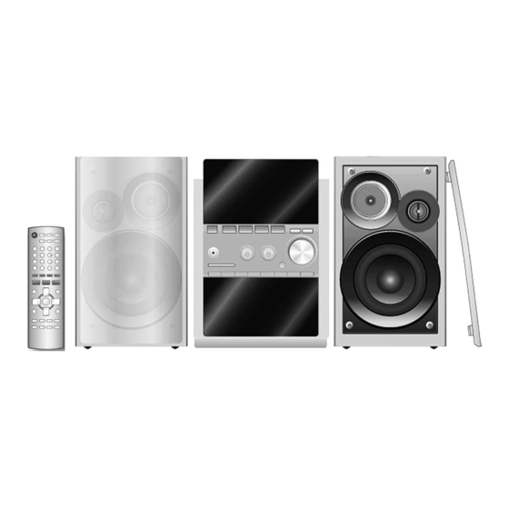
Specification
Type
Speaker (s)
Woofer
Tweeter
Super tweeter
Impedance
Input power (IEC)
High
Low
Output sound pressure
Crossover frequency
Frequency range
CONTENTS
3 way, 3 speaker system
10 cm cone type (6 Ω)
6 cm cone type (6 Ω)
2.5 cm piezo type
6 Ω
90 W (Max)
90 W (Max)
80 dB/W (1.0 m)
2.2 kHz
45 Hz to 35 kHz (-16 dB)
Page
3
3
4
4
5
5
6
7
SB-PM54GN
Colour
(M)... Wood Type
Dimensions (W x H x D)
Mass
Notes :
1. Specifications are subject to change without notice.
Mass and dimensions are approximate.
2. Total harmonic distortion is measured by the digital spectrum
analyzer.
3. The labels "HIGH" and "LOW" on the rear or the speakers refer to
High frequency and Low speakers refer to High frequency and Low
frequency.
© 2007 Matsushita Electric Industrial Co. Ltd.. All
rights
reserved.
distribution is a violation of law.
ORDER NO. MD0702005CE
Speaker System
50 Hz to 31 kHz (-10 dB)
144 x 249 x 200 mm
2.0 kg
Page
Unauthorized
copying
8
9
10
11
12
12
13
and
Advertisement
Table of Contents

Related Manuals for Panasonic SB-PM54GN


Summary of Contents for Panasonic SB-PM54GN
-
Page 1: Table Of Contents
ORDER NO. MD0702005CE Speaker System SB-PM54GN Colour (M)... Wood Type Specification Type 3 way, 3 speaker system 50 Hz to 31 kHz (-10 dB) Speaker (s) Dimensions (W x H x D) 144 x 249 x 200 mm 10 cm cone type (6 Ω) - Page 2 SB-PM54GN 6 Replacement Parts List...
-
Page 3: System Combination
SB-PM54GN 1 System Combination 1.1. System Breakdown Note : The table below show the breakdown for speaker combinations used in main unit systems. System SC-PM54GN-K Music center SA-PM54GN-K Speaker system SB-PM54GN-M... -
Page 4: Assembling And Disassembling
SB-PM54GN 2 Assembling and Disassembling “ATTENTION SERVICER” Some chassis components may have sharp edges. Be careful when disassembling and servicing. 1. This section describes procedures for checking the operation of the major printed circuit boards and replacing the main components. -
Page 5: Disassembly Of Net Frame Assembly
SB-PM54GN 2.2. Disassembly of Net frame 2.3. Disassembly of Front Panel assembly Follow (step 1) in item 2.2. Note: The disassembly process illustrates left speaker only. For right speaker, the disassembly process is the same. Step 1: Remove 4 screws. -
Page 6: Disassembly Of Piezzo Ornament
SB-PM54GN 2.4. Disassembly of Piezzo ornament Follow (step 1) in item 2.2. Follow (step 1) to (step 4) in item 2.3. Step 3: Insert a flathead screwdriver into the groove of the front panel as shown. Ensure that the screwdriver is above the small steel rule. -
Page 7: Disassembly Of Tweeter
SB-PM54GN Step 2: Insert the steel rule in between the tweeter and rear cabinet as arrow shown. Step 3: Remove glue from piezzo ornament. 2.5. Disassembly of Tweeter Follow (step 1) in item 2.2. Follow (step 1) to (step 4) in item 2.3. -
Page 8: Disassembly Of Woofer
SB-PM54GN 2.6. Disassembly of Woofer Follow (step 1) in item 2.2. Follow (step 1) to (step 4) in item 2.3. Step 3: Detach the red (+) and black (-) wires. Step 1: Remove 4 screws. Step 2: Insert the steel rule in between the woofer and rear... -
Page 9: Assembly Of Speaker Unit
SB-PM54GN 2.7. Assembly of Speaker Unit Step 1: Scrape off using the scriber and clean up the remaining glue at the 8 bosses and 8 holes of the front panel and rear cabinet and replace with new glue. Step 2: Fix the front panel firmly back to the rear cabinet. -
Page 10: Connection Of The Speaker Cables
SB-PM54GN 3 Connection of the Speaker Cables · Be sure to connect speaker cables before connecting the Connection AC power supply cord. · The load impedance of any speaker used with this unit must be 6 Ω. · Be sure to connect the cable from the right speaker to the right terminal and the cable from the left speaker to the left terminal. -
Page 11: Connection Of The Wiring Diagram
SB-PM54GN 4 Connection of the Wiring Diagram... -
Page 12: Exploded View
SB-PM54GN 5 Exploded view 5.1. Cabinet Parts Location... -
Page 13: Packaging
SB-PM54GN 5.2. Packaging... - Page 14 SB-PM54GN 6 Replacement Parts List Notes : · Important safety notice : When replacing any of these components, be sure to use only manufacturer’s specified parts shown in the parts list. · [M] markings in the Remarks columns indicates parts supplied by PAVCSG.