Makita DMP180 Repair Manual
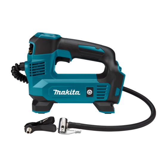
Cordless inflator
Hide thumbs
Also See for DMP180:
- Instruction manual (232 pages) ,
- Instruction manual (29 pages) ,
- Instruction manual (234 pages)
Table of Contents
Advertisement
Quick Links
Advertisement
Table of Contents

Related Manuals for Makita DMP180


Summary of Contents for Makita DMP180
- Page 1 OFFICIAL USE For ASC CORDLESS INFLATOR DMP180 REPAIR MANUAL August 2020 Ver.1...
-
Page 2: Table Of Contents
CONTENTS CONTENTS ....................................2 CAUTION ....................................3 NECESSARY REPAIRING TOOLS ............................3 REPAIR ......................................4 Battery ....................................4 4-1-1 Disassembling ................................4 Motor and Pump section ..............................4 4-2-1 Disassembling ................................4 4-2-2 Assembling .................................. 5 Switch/ Sensor, Terminal section/ Board ..........................6 4-3-1 Disassembling ................................ -
Page 3: Caution
CAUTION Repair the machine in accordance with "Instruction manual" or "Safety instructions". Follow the instructions described below in advance before repairing: Wear gloves. In order to avoid wrong reassembly, draw or write down where and how the parts are assembled, and what the parts are. ... -
Page 4: Repair
REPAIR Battery 4-1-1 Disassembling Remove the battery. Motor and Pump section 4-2-1 Disassembling Fig.1 Remove Swim ring adapter [1] and Ball adapter [2] from Fixed bracket. Fig.2 Remove Screws 3x14 [1] (10 pcs), then remove Housing. Remove Mats [2] (2 pcs). Fig.3 Remove Lead wires of Motor assembly [1] to release the lock by pinching the claw on the... -
Page 5: Assembling
Fig.4 Loosen and remove Hose [1] with Wrench 10 [2] (781036-5). Note Only a thin wrench [2] can be inserted, so be careful when loosening. As adhesive is applied to the thread on Hose end, be careful when you loosen it. 4-2-2 Assembling Fig.5... -
Page 6: Switch/ Sensor, Terminal Section/ Board
Switch/ Sensor, Terminal section/ Board 4-3-1 Disassembling Fig.8 Remove Switch trigger [1] carefully so that Spring [2] does not pop out. Fig.9 Remove Screw 3 *10 [1], then remove the following parts: Switch [2] Trigger spring-fixed block [3] ... -
Page 7: Assembling Of Terminal Section/ Board
Assembling of Terminal section/ Board Fig.12 When assembling PCB board [1], make sure that it is in the groove of Housing [2]. Fig.13 Align the groove of Battery terminal [1] with the rib of Housing. 7 / 9... -
Page 8: Assembling Of Switch/ Sensor
4-3-2 Assembling of Switch/ Sensor Fig.14 Assemble Power on/ off [1] so that the red switch side faces to the yellow arrow side, then tighten Screws 3*10 [2] (2 pcs). Fig.15 Assemble Switch [1] into two bosses. Assemble Digital display [2] and LED PCB [3]. Tighten SCREW 3*10 [5] carefully so as not to pinch Lead wires with Trigger spring-fixed block [4]. -
Page 9: Check After Repair
Check after REPAIR Check the operation of the repaired machine. Check that neither abnormal noise nor leakage of compressed air happens. Check that the digital monitor is displayed, and the LED light is light up. Check by putting air into the tires of the car, etc. ...