Table of Contents
Advertisement
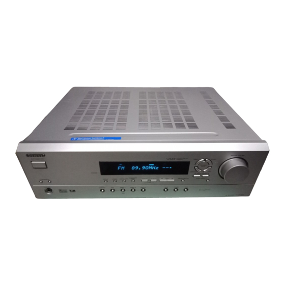
AV Receiver
TX-SR302
Instruction Manual
Thank you for purchasing an Onkyo AV Receiver.
Please read this manual thoroughly before making
connections and plugging in the unit.
Following the instructions in this manual will enable
you to obtain optimum performance and listening
enjoyment from your new AV Receiver. Please retain
this manual for future reference.
Contents
Before using
Important Safety Instructions ........................... 2
Precautions ........................................................ 3
Features ............................................................. 4
Supplied accessories ......................................... 4
Before Using the TX-SR302 ............................ 5
Facilities and connections
Index to parts and controls ............................... 6
Connecting to audio/video equipment ........... 10
Connecting antennas ....................................... 14
Enjoying music or videos
TX-SR302 .................................................... 17
Speaker setup .................................................. 18
to your connections ...................................... 21
Listening to the radio ...................................... 22
Enjoying multi channel sources ..................... 27
Enjoying the listening modes ......................... 28
Audio adjust function ..................................... 30
Recording a source ......................................... 32
Remote controller
AV components ............................................ 33
Appendix
Troubleshooting .............................................. 35
Specifications ................................................. 37
) ............. 16
E
n
Advertisement
Table of Contents

Related Manuals for Onkyo TX-SR302


Summary of Contents for Onkyo TX-SR302
-
Page 1: Table Of Contents
AV Receiver TX-SR302 Instruction Manual Thank you for purchasing an Onkyo AV Receiver. Please read this manual thoroughly before making connections and plugging in the unit. Following the instructions in this manual will enable you to obtain optimum performance and listening enjoyment from your new AV Receiver. -
Page 2: Important Safety Instructions
WARNING: TO REDUCE THE RISK OF FIRE OR ELECTRIC SHOCK, DO NOT EXPOSE THIS APPARATUS TO RAIN OR MOISTURE. CAUTION: TO REDUCE THE RISK OF ELECTRIC SHOCK, DO NOT REMOVE COVER (OR BACK). NO USER-SERVICEABLE PARTS INSIDE. REFER SERVICING QUALIFIED PERSONNEL. -
Page 3: Precautions
AC outlet voltages vary from country to country. Make sure that the voltage in your area meets the voltage requirements printed on the TX-SR302’s rear panel (e.g., AC 230 V, 50 Hz or AC 120 V, 60 Hz). Setting the [STANDBY/ON] switch to STANDBY does not fully shutdown the TX-SR302. -
Page 4: Features
Check that the following accessories are supplied with the TX-SR302. AM loop antenna × 1 The alphabet displayed at the end of the product name found in catalogs and on the packages represents the color of this receiver. Though the color varies, the specifications and operations are the same. -
Page 5: Before Using The Tx-Sr302
• Flat batteries should be removed as soon as possible to prevent possible leakage and corrosion. Using the Remote Controller To use the remote controller, point it at the TX-SR302’s remote control sensor, as shown below. The TX-SR302’s STANDBY indicator flashes while a signal is being received from the remote controller. -
Page 6: Index To Parts And Controls
5 seconds then show the current sound input source. Pressing the button again returns the TX-SR302 to the standby state. This state turns off the display, disables control functions. STANDBY indicator [17] Lights when the TX-SR302 is in the standby state and flashes when a signal is received from the remote controller. - Page 7 Index to parts and controls Display DISPLAY button [25] Each time you press the DISPLAY button, the display changes. AUDIO SELECTOR button [26, 27] Press to select an audio input signal format other than FM and AM. Each time this button is pressed, the setting cycles. Input selector buttons (DVD, VIDEO 1, VIDEO 2, VIDEO 3, TAPE, TUNER, and CD) [17, 21-23, 26, 27, 32]...
- Page 8 (REC) to the VIDEO 1 OUT jacks. Connect the output terminals of the video cassette player or satellite tuner to the VIDEO 2 IN or VIDEO 3 IN jacks on the TX-SR302. DVD [11] Connect the DVD player. If the DVD player has 5.1 channel output terminals, connect each terminal to the FRONT L/R, CENTER, SUBWOOFER, and SURR L/R terminals on the TX-SR302.
- Page 9 Index to parts and controls Remote controller RC-479S Explanations on this page are for controlling the TX-SR302. To operate other components, see “Using the remote controller with your other AV components” on pages 33 through 34. For operational instructions, refer to the page indicated in brackets.
-
Page 10: Connecting To Audio/Video Equipment
Connecting to audio/video equipment Before connecting • Be sure to always refer to the instruction manual that came with the component that you are connecting. • Do not plug in the power cord until all connections have been made. • For input jacks, red connectors are used for the right channel, white connectors are used for the left channel, and yellow connectors are used for video connection. - Page 11 To connect the digital output to the OPTICAL input jack of this unit, it is required to change the assignment of digital inputs to input sources by referring to “Setting the digital inputs” on page 21. If you have an LD player with AC-3RF output, connect via an AC-3RF demodulator to one of the TX-SR302’s DIGITAL INPUT terminals.
-
Page 12: Positioning Speakers/Connecting Speakers
Positioning speakers/Connecting speakers Two speaker systems can be connected to the Receiver. The speaker system A is to be placed in the main room, and the speaker system B is to be placed in a second room. The speaker system A consists of the FRONT SPEAKERS A (L/R), CENTER SPEAKER, SURROUND SPEAKERS (L/R) and SUBWOOFER. - Page 13 (+) and negative (–) speaker wires. • Do not connect more than one speaker cable to one speaker terminal. Doing so may damage the TX-SR302. • When you are using only one speaker or when you wish to listen to monaural (mono) sound, a single speaker should never be connected in parallel to both the right and left channel terminals simultaneously.
-
Page 14: Connecting Antennas
The AM loop antenna is for indoor use only. Set it in the direction and position where you receive signals clearly. Put it as far away as possible from the TX-SR302, televisions, speaker cables, and power cords. When reception is not satisfactory with the attached AM loop antenna alone, connection of an outdoor antenna is recommended. - Page 15 Connecting antennas Connecting an Outdoor FM Antenna If you cannot achieve good reception with the supplied indoor FM antenna, try a commercially available outdoor FM antenna instead. Notes • Outdoor FM antennas work best outside, but usable results can sometimes be obtained when installed in an attic or loft. •...
-
Page 16: Connections For Remote Control
Power on/ready function terminal. When a When the TX-SR302 is in the standby state, if an component is turned on, then the TX-SR302 also turns on and the input source selected at the TX-SR302 automatically switches to that component. If the power cord for an... -
Page 17: Enjoying Music Or Videos With The Tx-Sr302
• Make sure that all the connections from pages 10 to 16 are complete. • Turning on the AV Receiver may cause a momentary power surge, which might interfere with other electrical equipment such as computers. If this happens, use a wall outlet on a different circuit. -
Page 18: Speaker Setup
Speaker setup You need to set up the speaker configuration for the speaker system A (see page 12). (There is no speaker configuration setup for the speaker system B.) It is not necessary to set the parameters again once you have completed the setup unless you change the speaker configuration. - Page 19 Speaker setup Specifying speaker distances To get the best from surround sound, it’s important that the sound from each speaker reaches the listener at the same time. To achieve this, you need to specify the distance from each speaker to the listening position.
-
Page 20: Setting The Subwoofer Mode
Speaker setup SUBWOOFER MODE Setting the subwoofer mode Press SUBWOOFER MODE on the unit. With the first press of the button, you can check the present setting. Then each press of the button changes the subwoofer mode as follows (a tip on how to select the right subwoofer mode is in parenthesis): →... -
Page 21: Changing The Default Settings According To Your Connections
Switch the source from TAPE to MD You can set the AV receiver to show “MD” when the TAPE source is selected by pressing TAPE on the unit. 1 Press TAPE to select the input source. -
Page 22: Listening To The Radio
Listening to the radio There are two ways to select radio stations: • Manual tuning • Presetting radio stations then selecting the preset channels Tuning into a radio station 1. Press TUNER. The selected band appears in the display. Each time you press the button, the band changes as follows: AM ↔... - Page 23 Listening to the radio FM MODE MEMORY Presetting radio stations You can preset up to 30 stations. 1. Tune in the radio station you wish to preset (refer to the previous page). 2. Press MEMORY. The MEMORY indicator lights and the preset number starts flashing in the display.
-
Page 24: Various Functions Common To All The Sources
If you turn off the unit during muting, and turn it on again, the sound will be restored. Listening through headphones Connect the plug of the stereo headphones to the PHONES jack on the AV Receiver. Notes • The speakers will not reproduce sound while headphones are connected. - Page 25 Press SLEEP. “Sleep 90 min” appears in the multipurpose display for about 5 seconds, which means the AV Receiver will turn off and enter standby mode in 90 minutes. Also the SLEEP indicator is lit in the display while the sleep timer is on.
- Page 26 The adjusted values will return to the values set on page 20 when the AV Receiver enters standby mode unless you save the values. Note You cannot adjust the volume balance while the muting function is activated.
-
Page 27: Enjoying Multi Channel Sources
Enjoying multi channel sources SURROUND AUDIO SELECTOR Using analog multi channel input The multi channel input refers to a system, which is compatible with a source component equipped with analog 5.1-channel outputs (DVD player, MPEG decoder, etc.), reproducing the left/right front, center and left/right surround channels from five respective speakers and outputting the subwoofer channel from SUB WOOFER (refer to page 13). -
Page 28: Enjoying The Listening Modes
DTS source, a short noise may be heard. This is not a malfunction. • The DTS indicator on the TX-SR302 lights up while it plays the DTS source. When playback concludes and the DTS signal transmission stops, the TX-SR302 remains in DTS mode and the DTS indicator remains lit. - Page 29 DTS). A.STEREO button: Set the listening mode to “All Ch St”. DSP button on the front panel: Recall the Onkyo-original DSP mode. Each time this button is pressed, the listening mode cycles; “Orchestra” → “Unplugged” → “Studio Mix” → “TV Logic” →...
-
Page 30: Audio Adjust Function
Audio adjust function Using the audio adjust functions Before operating the remote controller, press RCVR/TAPE. These functions only work with speaker system A. Audio Adjust provides various functions for adjusting the sound, including several especially for use with Dolby Digital, DTS, and Pro Logic II source. - Page 31 Note that the impact of the Late Night function depends on the Dolby Digital source that you are playing, and with some source there will be little or no effect. This function is automatically cancelled when you set the TX-SR302 to Standby. Cinema Filter...
-
Page 32: Recording A Source
Recording a source To record the input source signal you are currently watching or listening to Recording of video and/or audio signals can be performed on the components connected to the VIDEO 1 OUT and TAPE OUT (audio only) jacks. Input selector buttons 1. -
Page 33: Using The Remote Controller With Your Other Av Components
In the following illustrations, buttons that control the TX-SR302 regardless of which mode is selected are shaded. When you want to control the TX-SR302 fully, press the RCVR/TAPE button, then you can use all the buttons that apply to the TX-SR302. operation buttons Power On/Off. -
Page 34: Using The Remote Controller With Your Other Av Components
Using the remote controller with your other AV components CD mode operation buttons CD input selector Power On/Off. Starts playback of CD. Stops playback, fast forward or fast reverse. Fast forwards of CD. Fast reverses of CD. L e t s p l a y b a c k temporarily. -
Page 35: Troubleshooting
Remedies • Check the connection of the power cord. • Disconnect the power cord, then connect it again. • Contact your Onkyo Service Center. • Disconnect the power cord, then connect it again. • Deactivate the muting function. • Check the connections to the AV receiver. - Page 36 To reset the surround mode and other settings to the factory default settings, hold down the VIDEO 1 button with the TX-SR302 turned on and then press the STANDBY/ON button. “Clear” appears in the front display and the TX-SR302 enters the standby state.
-
Page 37: Specifications
Specifications Amplifier Section Power Output Front L/R: 65 W + 65 W Center: 65 W Surround L/R: 65 W + 65 W (8 Ω, 20 Hz~20 kHz, FTC) 160 W + 160 W (3 Ω, Front) Dynamic Power: 125 W + 125 W ( 4 Ω, Front) 85 W + 85 W (8 Ω, Front) (Total Harmonic Distortion): 0.08 % (Power Rated) - Page 38 Memo...
- Page 39 Memo...
- Page 40 ONKYO CHINA LIMITED Units 2102-2107, Metroplaza Tower I, 223 Hing Fong Road, Kwai Chung, N.T., HONG KONG Tel: 852-2429-3118 Fax: 852-2428-9039 SN 29343913 (C) Copyright 2004 ONKYO CORPORATION Japan. All rights reserved. HOMEPAGE http://www.onkyo.com/ D0409-1 * 2 9 3 4 3 9 1 3 *...