Garmin GPSMAP 5215 Installation Instructions Manual
Gpsmap 4000 series; gpsmap 5000 series
Hide thumbs
Also See for GPSMAP 5215:
- Owner's manual (116 pages) ,
- Important safety information (4 pages) ,
- Technical reference (42 pages)
Table of Contents
Advertisement
GPSMAP
4000/5000 Series Installation Instructions
®
The GPSMAP 4000/5000 series chartplotter and GPS antenna must be properly installed according to the following instructions. You need the
appropriate fasteners, tools, and mounts listed in each section. These items are available at most marine dealers.
CAutIon
Always wear safety goggles, ear protection, and a dust mask when drilling, cutting, or sanding.
notice
When drilling or cutting, always check what is on the opposite side of the surface.
Mount the GPSMAP 4000/5000 series chartplotter in a location that provides a clear, glare-free view of the display and easy operation of the
controls or touch screen.
Contact Garmin Product Support if you have any questions while installing your GPSMAP 4000/5000 Series chartplotter. In the USA, go to
www.garmin.com/support, or contact Garmin USA by phone at (913) 397.8200 or (800) 800.1020.
In the UK, contact Garmin (Europe) Ltd. by phone at 0808 2380000.
In Europe, go to
www.garmin.com/support
and click
Contact Support
for in-country support information, or contact Garmin (Europe) Ltd. by
phone at +44 (0) 870.8501242.
Before installing your GPSMAP 4000/5000 series chartplotter, confirm that the package contains the items listed on the box. If any parts are
missing, contact your Garmin dealer immediately.
WArnInG
See the Important Safety and Product Information guide in the product box for product warnings and other important information.
to install the GPSMAP 4000/5000 series chartplotter, you must:
1. Mount the GPSMAP 4000/5000 series chartplotter (page 2).
2. Mount the GPS antenna (page 5).
3. Connect the GPSMAP 4000/5000 series device to power and to the GPS antenna (pages 8-9).
4. Create a NMEA 2000 network or connect the chartplotter to an existing NMEA 2000 network (page 10).
5. Connect the GPS 17x antenna to the NMEA 2000 network (page 10).
6. Ensure the chartplotter software is up-to-date (page 20).
Although they are not necessary to use the GPSMAP 4000/5000 chartplotter, this manual covers other installation options:
• Connecting the chartplotter to other Garmin Marine Network compatible devices, such as a sounder or a radar (page 15).
• Connecting the chartplotter to other NMEA 0183-compatible devices such as a VHF radio with DSC (page 15).
• Connecting the chartplotter to an external alarm (page 18).
• Connecting the chartplotter to a video input source (page 19).
• Connecting the chartplotter to an external video monitor (page 19).
August 2011
Part Number 190-00779-02 Rev. J
Printed in Taiwan
Advertisement
Table of Contents

Related Manuals for Garmin GPSMAP 5215


Summary of Contents for Garmin GPSMAP 5215
- Page 1 Mount the GPSMAP 4000/5000 series chartplotter in a location that provides a clear, glare-free view of the display and easy operation of the controls or touch screen. Contact Garmin Product Support if you have any questions while installing your GPSMAP 4000/5000 Series chartplotter. In the USA, go to www.garmin.com/support, or contact Garmin USA by phone at (913) 397.8200 or (800) 800.1020.
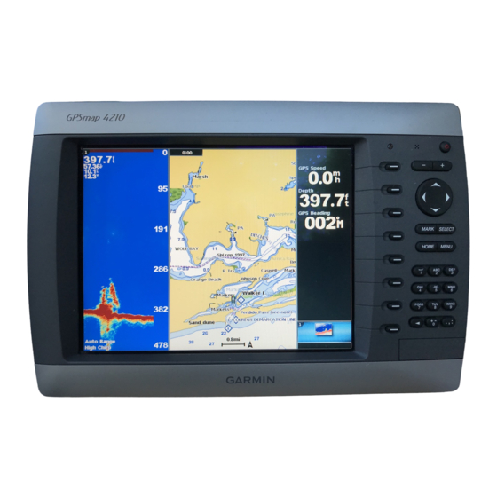
- Page 2 Mounting the GPSMAP 4000/5000 Series Chartplotter You can mount the GPSMAP 4000/5000 series chartplotters one of two ways. You can use the included bracket to bail mount the chartplotter, or you can use the included template and hardware to flush mount the chartplotter. You cannot bail mount the GPSMAP 5015/5215 chartplotters.
- Page 3 Flush Mounting the GPSMAP 4000/5000 Series Chartplotter The flush-mount method you will use with your chartplotter is dependent on the model. Be sure to follow the instructions for your chartplotter model. Flush Mounting a GPSMAP 4008/4208/4012/4212 Chartplotter or a GPSMAP 5008/5208/5012/5212 Chartplotter Hardware (included): • Flush-mount template...
- Page 4 Rubber gasket Flush Mounting a GPSMAP 4008/4208/4012/4212/5008/5208/5012/5212 Chartplotter Flush Mounting a GPSMAP 4010/4210 Chartplotter or a GPSMAP 5015/5215 Chartplotter: Hardware (included): • Flush-mount template • Rubber gasket • Mounting screws (4.2 × 1.4 DIN7981 / number 8 ANSI) to flush mount a GPSMAP 4010/4210 chartplotter or a GPSMAP 5015/5215 chartplotter: 1. The flush-mount template is included in the product box. Trim the template and ensure it will fit in the location where you want to flush mount the chartplotter.
-
Page 5: Mounting The Gps 17X Antenna
10. P lace the chartplotter into the cutout. 11. S ecurely tighten the included mounting screws through the chartplotter into the pilot holes. NOTE: Stainless-steel screws may bind when screwed into fiberglass and overtightened. Garmin recommends applying an anti-galling, stainless anti- seize lubricant to the screw before using. 12. R eplace the mounting covers by snapping them into place. Be sure to follow the correct mounting directions and the correct wiring directions for the antenna included with your chartplotter. - Page 6 Mounting the Antenna on a Surface 1. Select a mounting location for the antenna, and verify correct operation at the mounting location. 2. Trim the surface-mount template, and make sure the antenna fits in the mounting location you selected. 3. Remove the protective liner on the back of the template, and apply the template to the mounting location. 4. Use a in. (3.2 mm) bit to drill the three pilot holes indicated on the template. If you are mounting the GPS 17x on fiberglass, it is recommended to use a countersink bit to drill a clearance counterbore through the top gelcoat layer (but no deeper).
- Page 7 4. At the marked location, use a in. (19 mm) bit to drill a hole for the cable to pass through. 5. Fasten the marine pole mount to the boat (hardware not included). 6. Thread the pole-mount bracket onto the marine pole mount. ➊ Do not overtighten the bracket. 7. Route a NMEA 2000 drop cable through the pole-mount bracket and the pole, and connect the cable to the antenna. 8. Place the antenna on the pole-mount bracket, and twist it clockwise 9. Secure the antenna to the bracket with the included M3 set screw 10. R oute the NMEA 2000 drop cable away from sources of electronic interference. 11. C onnect the antenna to your NMEA 2000 network. 12. A fter the antenna is installed on the pole mount, fill the vertical cable slot with a marine sealant (optional). Mounting the Antenna under a Surface When choosing a location to install the under-deck-mounting bracket, make sure the included screws are not too long for the surface thickness. If the screws are not appropriate for the surface, you must supply the correct length of M4 screws to avoid damage to the top of the mounting surface.
-
Page 8: Wiring And Cables
• The NMEA 2000 cables and connectors come with the locking rings pre-installed. Do not remove the locking ring from a NMEA 2000 cable while routing the cable. • Optional Garmin Marine Network components use specialized Garmin Network cables (not included). Each network cable is also packaged with a separate locking ring, in a bag labeled with a GPSMAP 4000/5000 cable. -
Page 9: Wiring The Power Cable
5. Insert the O-ring into the end of the connector. Installing a Locking ring Wiring the Power Cable The GPSMAP 4000/5000 series chartplotter must be connected to the power supply for the boat. Use the 2-pin power cable included, and connect the power (red) and ground (black) wires. NOTES: •... -
Page 10: Connecting To An Existing Nmea 2000 Network
The GPSMAP 4000/5000 series chartplotter is packaged with the necessary NMEA 2000 connectors and cable to either connect the GPSMAP 4000/5000 series chartplotter and GPS 17x antenna to your existing NMEA 2000 network, or to build a basic NMEA 2000 network. For more information on NMEA 2000, visit www.garmin.com. Connecting to an Existing nMEA 2000 network If your boat already has a NMEA 2000 network installed, use the included T-connectors and drop cable to connect the GPSMAP 4000/5000 series chartplotter and GPS 17x antenna to the existing network. -
Page 11: Creating A Basic Nmea 2000 Network
Creating a Basic nMEA 2000 network If your boat does not already have an existing NMEA 2000 network installed, you will need to create a basic NMEA 2000 network. For more information on NMEA 2000, visit www.garmin.com. to create a basic nMEA 2000 network 1. Connect the three included T-connectors together by their sides. -
Page 12: Wiring A Garmin Marine Network
• NMEA 0183 devices must all be wired to one chartplotter on the network. The data is then shared over the network to other connected chartplotters. • Connect all chartplotters to the NMEA 2000 network as well as to the Garmin Marine Network. NMEA 2000 data is not shared over the Garmin Marine Network. - Page 13 NOTES: • Every device connected to the Garmin Marine Network must be connected to the power supply for the boat. These diagrams show the network connections; however, they do not show the power connections. Wire each device according to the appropriate installation instructions.
- Page 14 Network data, but do not share cartography. • Every device connected to the Garmin Marine Network must be connected to the power supply for the boat. This diagram shows the network connections; however, it does not show the power connections. Wire each device according to the appropriate installation instructions.
-
Page 15: Wiring Additional Nmea 0183 Devices
These diagrams illustrate basic NMEA 0183 wiring used to connect your GPSMAP 4000/5000 series chartplotter to NMEA 0183-compliant devices such as an AIS or DSC device. For more-complete information on the NMEA 0183 capabilities of the GPSMAP 4000/5000 series chartplotter, see the section on advanced NMEA 0183 wiring Garmin GPSMAP 4000/5000 series chartplotter... -
Page 16: Advanced Nmea 0183 Wiring
• Approved NMEA 0183 sentences—GPBWC, GPRMC, GPGGA, GPGSA, GPGSV, GPGLL, GPBOD, GPRMB, GPRTE, GPVTG, GPWPL, GPXTE, and Garmin proprietary sentences —PGRME, PGRMM, and PGRMZ. • The GPSMAP 4000/5000 series chartplotter also includes support for the WPL sentence, DSC, and sonar NMEA 0183 input with support for the DPT (depth) or DBT, MTW (water temperature), and VHW (water temperature, speed, and heading) sentences. - Page 17 Garmin GPSMAP 4000/5000 series chartplotter Wiring to a Standard nMEA 0183-compliant Device with 2-way Communication Garmin GPSMAP 4000/5000 series chartplotter Wiring to a Standard nMEA 0183-compliant Device for one-Way Communication Garmin GPSMAP 4000/5000 series chartplotter Wiring to Send Data to a nMEA 0183-compliant Device With a Single Wire tX Connection...
-
Page 18: Wiring To A Db-9 Pc Serial Connector
The maximum current is 100 mA, and a relay is needed to limit the current from the chartplotter to 100 mA. To select between visual and audible alerts, install a switch. Garmin GPSMAP 4000/5000 series... - Page 19 Wiring to a GPS 17 or GPS 17 HVS Antenna If you already have a Garmin GPS 17 or GPS 17 HVS installed on your boat, you can wire it to the GPSMAP 4000/5000 series chartplotter instead of installing the included GPS 17x. Wire the existing GPS 17 or GPS 17 HVS antenna to the included 19-pin NMEA 0183 cable as well as to the power supply for the boat, referring to the diagram below.
-
Page 20: Updating The Chartplotter Software
To attach a Garmin Marine Network cable or a NMEA 2000 Micro-connector cable, carefully press the cable into the correct port on the back of the chartplotter until it is firmly seated. Do not force the cable, because this may damage the pins. After the cable is seated, turn the locking ring clockwise until it is tight. -
Page 21: Specifications
Specification Devices Size 4008, 4208 4010, 4210 4012, 4212 5008, 5208 5012, 5212 5015, 5215 Weight 4008, 4208 4010, 4210 4012, 4212 5008, 5208 5012, 5212 5015, 5215 Display 4008, 4208 4010, 4210 4012, 4212 5008, 5208 5012, 5212 5015, 5215 Case All models Temp. Range All models Compass Safe 4008, 4208, 5008, 5208 Distance 4012, 4212, 5012, 5212 4010, 4210 5015, 5215 Power Specification Source Usage Fuse NMEA 2000 Load Equivalency Number (LEN) All models NMEA 2000 Unit Draw GPSMAP 4000/5000 Series Installation Instructions Specifications... -
Page 22: Nmea 2000 Pgn Information
nMEA 2000 PGn Information receive 059392 ISO Acknowledgment 059904 ISO Request 060928 ISO Address Claim 126208 NMEA - Command/Request/Acknowledge Group Function 126464 Transmit/Receive PGN List Group Function 126992 System Time 126996 Product Information 127250 Vessel Heading 127489 Engine Parameters - Dynamic 127488 Engine Parameters - Rapid Update 127505 Fluid Level 128259 Speed - Water Referenced 128267 Water Depth 129025 Position - Rapid Update 129026 COG & SOG - Rapid Update 129029 GNSS Position Data 129539 GNSS DOPs 129540 GNSS Sats in View 130306 Wind Data... - Page 23 GPSMAP 4000/5000 Series Installation Instructions...
- Page 24 For the latest free software updates (excluding map data) throughout the life of your Garmin products, visit the Garmin Web site at www.garmin.com. © 2011 Garmin Ltd. or its subsidiaries Garmin International, Inc. 1200 East 151 Street, Olathe, Kansas 66062, USA Garmin (Europe) Ltd. Liberty House, Hounsdown Business Park, Southampton, Hampshire, SO40 9LR UK Garmin Corporation No. 68, Zhangshu 2 Road, Xizhi Dist., New Taipei City, 221, Taiwan (R.O.C.) www.garmin.com...