
Related Manuals for Dell VxRail E660


Summary of Contents for Dell VxRail E660
- Page 1 Dell VxRail™ E660, E660F, and E660N Installation and Service Manual January 2023 Rev. 8...
- Page 2 A WARNING indicates a potential for property damage, personal injury, or death. © 2021 - 2023 Dell Inc. or its subsidiaries. All rights reserved. Dell Technologies, Dell, and other trademarks are trademarks of Dell Inc. or its subsidiaries. Other trademarks may be trademarks of their respective owners.
-
Page 3: Table Of Contents
Contents Revision history..................................4 Chapter 1: Introduction......................... 5 Dell Technologies Support..............................5 Register for a Dell Technologies Support account....................5 Where to go for support resources...........................5 Use SolVe Online for VxRail procedures........................6 Locate your VxRail serial number............................ 6 Look up your VxRail serial number in VxRail Manager..................6 Locate the serial number and service tag number on your VxRail..............6... -
Page 4: Revision History
November 2021 Updated for VxRail software version 7.0.300, updated the PSU as fault tolerant redundant, and added the support for 256 GB LRDIMM for VxRail E660 and E660F. August 2021 Updated to include support for Intel Persistent Memory 200 series (BPS) and minor updates. -
Page 5: Chapter 1: Introduction
Introduction The VxRail E660, E660F, and E660N Installation and Service Manual provides an overview about the system, diagnostic tools, and guidelines describing high-level operations. The target audience for this document includes customers, field personnel, and partners who want to operate and maintain a VxRail E660, E660F, or E660N. -
Page 6: Use Solve Online For Vxrail Procedures
To view the PSNT and other labels, pull out the information tag in the front of the VxRail. Alternatively, information may be on a sticker on the chassis of VxRail. The mini Enterprise Service Tag (EST) is found on the back of VxRail. This information is used by Dell to route support calls to the appropriate personnel. -
Page 7: Chapter 2: System Overview
For more information about supported drives, see the Dell VxRail™ E660, E660F, and E660N Technical Specifications. Front view of the system The following figure shows the front view of the VxRail E660, E660F, and E660N 10 x 2.5-inch drive system: Item... -
Page 8: Rear View Of The System
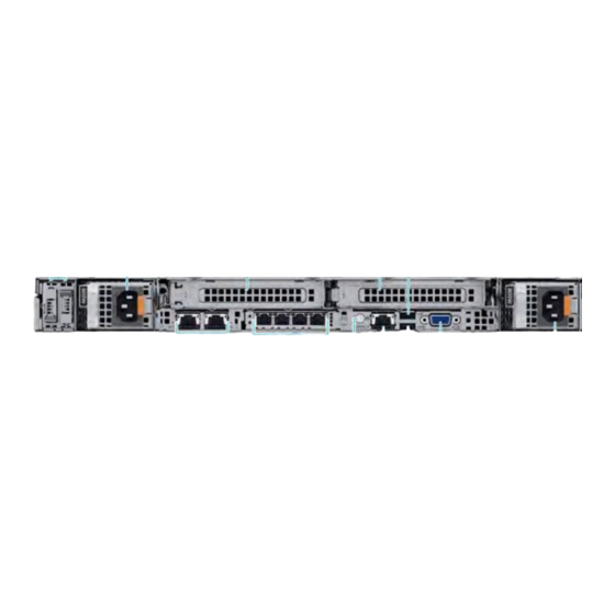
For more information about the ports, see the Dell VxRail E660, E660F, and E660N Technical Specifications. Rear view of the system The following figure shows the rear view of VxRail E660 and E660F with 2 x FH PCIe slots: Item... - Page 9 For more information, see the Dell VxRail E660, E660F, and E660N Technical Specifications. The following figure shows the rear view of VxRail E660, E660F, and E660N with 3 x LP PCIe slots: Item Ports, panels, or slots...
-
Page 10: Inside The System
BOSS S2 module This slot supports the BOSS S2 module. For more information, see the Dell VxRail E660, E660F, and E660N Technical Specifications. Inside the system The following figure shows the components inside the system: 1. - Page 11 7. Power supply unit (PSU 1) 8. BOSS S2 module 9. Processor socket 10. Memory DIMM slot for processor 1 (A6) 11. Drive backplane 12. fPERC (front mounted) 13. Service Tag System overview...
-
Page 12: Chapter 3: Initial Setup And Configuration
● You can purchase deployment services from Dell Technologies. If you are using VxRail deployment services from Dell Technologies, do not rack the VxRail or connect power. Contact your Dell Technologies account team or reseller to arrange for deployment by Dell Technologies certified technicians. -
Page 13: Chapter 4: Pre-Operating System Management Applications
Your VxRail was optimized by Dell Technologies during the initial configuration. NOTE: Do not change any of the basic settings or features set by Dell Technologies to ensure best performance. iDRAC configuration The Integrated Dell Remote Access Controller (iDRAC) is designed to make appliance administrators more productive and improve the overall availability of Dell appliances. -
Page 14: Chapter 5: Replacement Of Hardware Components
Supported hardware components section to know the components that you can replace. In addition to these components, there are some hardware components that require you to contact the Dell Technologies support to arrange for repair or replacement. Before you proceed with the replacement, go to SolVe and generate the replacement procedure of the component that you want to replace. -
Page 15: System Memory Guidelines
Drive backplane cover System memory guidelines The VxRail E660 series supports DDR4 registered DIMMs (RDIMMs), Load Reduced DIMM (LRDIMMs) and Intel Persistent Memory 200 series (BPS). System memory holds the instructions that are started by the processor. Your system memory is organized into eight channels per processor (two memory sockets per channel),16 memory sockets per processor, and 32 memory sockets per system. - Page 16 Figure 1. Memory channels The following table describes memory channels and how the channels are organized: Processor Channel A Channel B Channel C Channel D Channel E Channel F Channel G Channel H Processor 1 Slots A1 and Slots A5 Slots A3 and Slots A7 and Slots A2 and...
-
Page 17: General Memory Module Installation Guidelines
The following table describes the supported memory matrix: DIMM type Rank type Capacity DIMM rated Operating Speed voltage and 1 DIMM per 2 DIMMs per speed channel (DPC) channel (DPC) RDIMM 16 GB, 32 GB, 64 DDR4 (1.2 V), 3200 3200 MT/s 3200 MT/s MT/s... -
Page 18: Intel Persistent Memory 200 Series (Bps) Installation Guidelines
● Populate Intel Persistent Memory 200 series in DIMM slot 1, unless Intel Persistent Memory 200 series is the only DIMM in that channel, and then populate in DIMM slot 0. For more information about the supported Intel Persistent Memory 200 series (BPS) configurations, see the Dell Intel Persistent Memory 200 series (BPS) User's Guide at https://www.dell.com/support/home/products/server_int/server_int_poweredge. - Page 19 6+1 1 or 8+1 1 or 8+4 1 or 8+8 1 or 1 or The following table lists the BPS configurations in App Direct Mode for the single-socket configurations of VxRail E660 and E660F: Configuration Total No Total No of...
- Page 20 Configuration Total No Total No of 1 RDIMM/ 1 Intel Total Total PM Total Memory Intel LRDIMM Persistent Standard Capacity (GB) RDIMMs Persistent capacity Memory Memory (GB) Memory (GB) 200 series Capacity (GB) LRDIMM 200 series (BPS) (BPS) capacity DIMMs (GB) 1024 1024...
- Page 21 1216 1024 1408 1024 1792 1536 1024 2560 The following table lists the BPS configurations in App Direct Mode for the dual-socket configurations of VxRail E660 and E660F: Configuration Total No Total No of 1 RDIMM/ 1 Intel Total Total PM...
- Page 22 Configuration Total No Total No of 1 RDIMM/ 1 Intel Total Total PM Total Memory Intel LRDIMM Persistent Standard Capacity (GB) RDIMMs Persistent capacity Memory Memory (GB) Memory (GB) 200 series Capacity (GB) LRDIMM 200 series (BPS) (BPS) capacity DIMMs (GB) 4096 4224...
-
Page 23: Expansion Card Installation Guidelines
Configuration Total No Total No of 1 RDIMM/ 1 Intel Total Total PM Total Memory Intel LRDIMM Persistent Standard Capacity (GB) RDIMMs Persistent capacity Memory Memory (GB) Memory (GB) 200 series Capacity (GB) LRDIMM 200 series (BPS) (BPS) capacity DIMMs (GB) 2048 2048... - Page 24 Riser 2A - Low profile 1. Slot 1 2. Slot 2 Riser 3A - Low profile 1. Slot 3 Replacement of hardware components...
- Page 25 Riser 4 -Full height 1. Slot 2 The VxRail E660 and VxRail E660F supports the following riser configurations: ● Riser configuration 0-1: R2A + R3A NOTE: PCIe slot-1 supports single-socket configuration only. Location Width Length Height Processor 1 Processor 2...
- Page 26 Location Width Length Height Processor 1 Processor 2 Riser 2A Riser 2A Riser 3A PCIe Slot-3 Single-wide Half length Low profile ● Riser configuration 3: R1A + R4C + R4D Location Width Length Height Processor 1 Processor 2 Riser 2A Riser 4C Riser 4D PCIe Slot-1...
-
Page 27: Chapter 6: System Diagnostics And Indicator Codes
System diagnostics and indicator codes This section describes the chassis LEDs and diagnostic indicators on the front panel of VxRail E660 series. These diagnostic indicators display the system status during system startup. Status LED indicators The status LED indicators are located on the chassis and they indicate the condition of the system. If any error occurs, the indicators turn solid amber in color. -
Page 28: System Health And System Id Indicator Codes
Solid amber Indicates that the system is in fail-safe mode. If the problem persists, see Dell Technologies Support. Blinking amber Indicates that the system is experiencing a fault. Check the System Event Log for specific error messages. -
Page 29: Idrac Direct Led Indicator Codes
Solid amber Indicates that the system is in fail- Restart the system. safe mode. If the problem persists, see Dell Technologies Support. Blinking amber Indicates that the iDRAC Quick Restart the system. Sync 2 hardware is not responding... -
Page 30: Power Supply Unit Indicator Codes
Power supply unit indicator codes AC power supply units (PSUs) have an illuminated translucent handle that serves as an indicator. The indicator shows if power is present or if a power fault has occurred. 1. AC PSU handle 2. Socket 3. -
Page 31: Drive Indicator Codes
Using system diagnostics If you experience an issue with the system, run the system diagnostics before contacting Dell Technologies for technical assistance. The purpose of running system diagnostics is to test the system hardware without using additional equipment or risking data loss. - Page 32 Run the Embedded System Diagnostics from the Dell Lifecycle Controller Steps 1. When the system is booting, press F10. 2. Select Hardware Diagnostics → Run Hardware Diagnostics. The ePSA Pre-boot System Assessment window is displayed, listing all devices detected in the system. The diagnostics start executing the tests on all the detected devices.