Sony DSC-HX300 Service Manual
Hide thumbs
Also See for DSC-HX300:
- Instruction manual (595 pages) ,
- User manual (252 pages) ,
- Limited warranty (1 page)
Advertisement
Quick Links
SERVICE MANUAL
Ver. 1.1 2013.05
Internal memory
Internal memory
ON BOARD
ON BOARD
Revised-1
Replace the previously issued
SERVICE MANUAL 9-834-725-31
with this Manual.
SERVICE NOTE (Check the following note before the service.)
– ENGLISH –
1-1. PRECAUTION ON REPLACING THE SY-1016 BOARD
1-2. ADDITION OF DESTINATION DATA FILE
1-3. METHOD FOR COPYING OR ERASING THE DATA IN INTERNAL MEMORY
1-4. HOW TO WRITE DATA TO INTERNAL MEMORY
1-5. SELF-DIAGNOSIS FUNCTION
1-6. PROCESS AFTER FIXING FLASH ERROR
1-7. ORNAMENTAL PLATE REPLACING METHOD
1-8. 2ND ASSY REPLACING METHOD
1-9. FINAL INSPECTION
‒ JAPANESE ‒
1-1. SY-1016基板交換時の注意
1-2. Destination Data ファイルの追加について
1-3. 内蔵メモリーのデータコピーおよび消去方法
1-4 . 内蔵メモリーへデータを書き戻す方法
1-5. 自己診断機能
1-6. フラッシュエラー発生時の対処法
The components identified by
Les composants identifiés par
mark 0 or dotted line with mark
une marque 0 sont critiques pour
0 are critical for safety.
la sécurité.
Replace only with part number
Ne les remplacer que par une piè-
specified.
ce portant le numéro spécifié.
DSC-HX300_L2
9-834-725-32
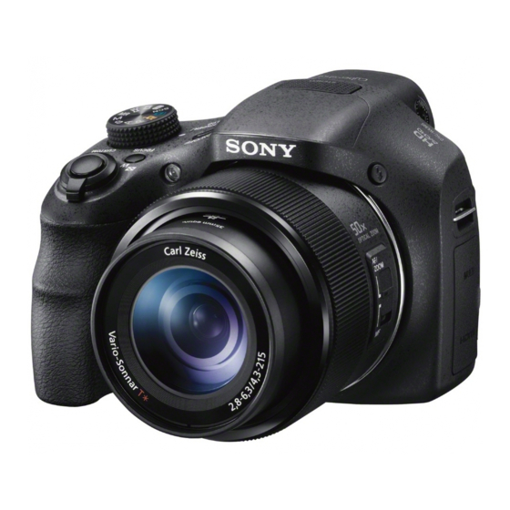
DSC-HX300
LEVEL
US Model
Canadian Model
AEP Model
UK Model
Russian Model
E Model
Australian Model
Hong Kong Model
Chinese Model
Korea Model
Brazilian Model
Japanese Model
Tourist Model
DIGITAL STILL CAMERA
Ver.
Date
History
2
1.0
2013.02
Official Release
1.1
2013.05
Revised-1
(A1 13-010)
Sony Corporation
Revision History
Contents
—
• Change of SERVICE NOTE.
Page 1-12,
1-14
• Change of REPAIR PARTS LIST.
Page
2-6
Published by Sony Techno Create Corporation
983472532.pdf
S.M. Rev.
issued
—
Yes
2013E08-1
© 2013.05
Advertisement

Related Manuals for Sony DSC-HX300


Summary of Contents for Sony DSC-HX300
- Page 1 0 sont critiques pour 0 are critical for safety. la sécurité. Replace only with part number Ne les remplacer que par une piè- specified. ce portant le numéro spécifié. 2013E08-1 DSC-HX300_L2 © 2013.05 Sony Corporation 9-834-725-32 Published by Sony Techno Create Corporation...
- Page 2 PRINT Image Matching III: Duo” media, “Memory Stick Compatible Micro” media, SD cards, microSD memory cards Model information table Model DSC-HX300 Destination US, CND, E, KR, BR, J AEP, UK, RU, E, AUS, HK, CH, JE Color system NTSC –...
- Page 3 DIAGRAMMES SCHÉMATIQUES ET LA LISTE DES PIÈCES SONT サービス,点検時には次のことにご注意ください。 ARE CRITICAL TO SAFE OPERATION. REPLACE THESE COMPO- CRITIQUES POUR LA SÉCURITÉ DE FONCTIONNEMENT. NE REM- NENTS WITH SONY PARTS WHOSE PART NUMBERS APPEAR AS PLACER CES COMPOSANTS QUE PAR DES PIÈCES SONY DONT 1. 注意事項をお守りください。 無鉛半田について...
- Page 4 1. SERVICE NOTE – ENGLISH – 1-1. PRECAUTION ON REPLACING THE SY-1016 BOARD 1-2. ADDITION OF DESTINATION DATA FILE DESTINATION DATA If the Destination Data file included in the Adjust manual is old, “DESTINATION DATA WRITE” cannot be executed in some cases. In that case, download a new Destination Data file from the TISS homepage according to the following procedure.
- Page 5 – ENGLISH – 3) Search the model whose new Destination Data file you want to get on the TISS homepage. 6) Click the [File Update] button in the window. When the Destination Data file has been updated, a file with a name “Destination File For ‘model name’.zip” is registered. (Example) Destination File For DSC-WX50.zip Furthermore, the version supported by the Destination Data file is shown in the Remarks column.
- Page 6 – ENGLISH – 1-3. METHOD FOR COPYING OR ERASING THE DATA IN INTERNAL MEMORY 1-4. HOW TO WRITE DATA TO INTERNAL MEMORY The data can be copied/erased by the operations on the MENU. (When erasing the data, execute formatting the internal memory.) Usually, the camera has been set so as to disable the data writing from the PC to the internal memory of the camera.
- Page 7 – ENGLISH – 1-5. SELF-DIAGNOSIS FUNCTION 1-5-3. Self-diagnosis Code Table Self-diagnosis Code 1-5-2. Self-diagnosis Display 1-5-1. Self-diagnosis Function When problems occur while the unit is operating, the LCD screen shows When problems occur while the unit is operating, the self-diagnosis func- a 4-digit display consisting of an alphabet and numbers, which blinks at tion starts working, and displays on the LCD screen what to do.
- Page 8 – ENGLISH – – JAPANESE – 1-6. PROCESS AFTER FIXING FLASH ERROR 1-1. SY-1016基板交換時の注意 When “FLASH error” (Self-diagnosis Code E : 91 : 01) occurs, to prevent any abnormal situation caused by high voltage, setting of the flash is changed 仕向けデータ...
- Page 9 – JAPANESE – 3) TISSホームページにて,新しい Destination Data ファイルを入手したい機種を検索する。 1-2. Destination Data ファイルの追加について Destination Data ファイルが更新されている場合, 「Destination File For ”機種名”.zip」 という名称のファイルが登録されてい Adjust manual に含まれる Destination Data ファイルが古い場合, 「DESTINATION DATA WRITE」 が実行できないことがあります。 る。 その場合は,下記の手順を参考にして, TISS ホームページより新しい Destination Data ファイル を入手してください。 (例) Destination File For DSC-WX50.zip Note 1: この機種で仕向け設定を行うには,DSC-WX50シリーズの Adjust manual がインストールされている必要があります。 先に DSC-WX50 シリーズの Adjust manual をインストールしてください。 また,Remarks欄にはこの Destination Data ファイルが対応するバージョンが記載されています。 Note 2: 手順中の画像は実際と異なる場合があります。 Note: バージョンが更新されていなかった場合は,サービスヘッドクォーターへお問い合わせください。 1) 使用している Adjust manual の Destination Data ファイルが古い場合, Fig. 1 のようなウインドウが表示される。 ...
- Page 10 – JAPANESE – 1-3. 内蔵メモリーのデータコピーおよび消去方法 6) ウインドウ内の [File Update] ボタンをクリックする。 内蔵メモリーのデータコピーまたは消去はメニュー操作から実行可能です。 (消去する場合は内蔵メモリーの初期化を行います。 ) Note1:SY-1016基板交換の際は,基板交換前に内蔵メモリーのデータを消去して下さい。 Note2:SY-1016基板交換の際は,基板交換後に内蔵メモリーのフォーマットおよび初期化を実行して下さい。 内蔵メモリーのコピー方法 7) ファイルを選択する画面が出るので,追加する Destination Data ファイルを選択し, [開く] ボタンをクリックする。 内蔵メモリー,もしくはメモリーカードのフォーマット方法 8) ファイルの追加が成功すると, 下記のような画面が出る。 9) Destination Ver. ウインドウを確認し,バージョンが更新されていることを確認する。 Destination Ver. ウインドウ DSC-HX300_L2...
- Page 11 – JAPANESE – 1-4 内蔵メモリーへデータを書き戻す方法 1-5. 自己診断機能 通常は,PCからカメラの内蔵メモリへデータを書き込むことはできない設定になっています。 1-5-1. 自己診断機能について 1-5-2. 自己診断表示 基板交換後などに,内蔵メモリへデータを書き戻す場合には,この設定を一時的に変更する必要があります。 本機の動作に不具合が生じたとき,自己診断機能が働き,LCD 本機の動作に不具合が生じたとき,LCD画面にアルファベッ 設定の変更は,Adjust StationからAdjust Manualを起動させて書き込み許可ツール (Write Enable Tool) を使用します。 画面に,どう処置したらよいか判断できる表示を行います。自 トと4桁の数字が表示され,3.2Hzで点滅します。この5文字の 己診断機能については取扱説明書にも掲載されて 表示によって対応者分類および不具合の生じたブロックの分 書き戻し方法 います。 類,不具合の詳細コードを示します。 1) Adjust StationからAdjust Manualを起動する。 LCD画面 2) (Write Enable Tool) ボタンをクリックする。 3) “Activate Write Enable Mode”ボタンをクリックする。 3.2 Hz点滅 詳細コード 対応者分類 ブロック分類 C :お客さま自身で対応 対応方法の違いにより分類 「1‑5‑3. 自己診断コード表」を参照 ...
- Page 12 – JAPANESE – 1-5-3. 自己診断コード表 1-6. フラッシュエラー発生時の対処法 自己診断コード 本機はフラッシュエラー(自己診断コードE:91:01) が発生した場合,高電圧による異常を防止するために自動的にフラッシュ充 対 電および発光禁止の設定になります。 症状/状態 対応/方法 ブロック 詳細 応 フラッシュエラー発生後はエラーの解除を行う必要があります。 機能 コード 者 内蔵メモリーに メディアエラー があっ 電源を入れ直す。 た。 フラッシュエラーの解除方法 内蔵メモリーにフォーマットエラーが 内蔵メモリーをフォーマットする。 あった。 Flash Error Repair Tool Ver̲[].[].exe を使用して Flash Error を解除してください。 フォーマットしていないメモリーカー メモリーカードをフォーマットする。 ドを入れた。 メモリーカードが壊れている。 新しいメモリーカードに交換する。 メモリーカードのタイプエラーを検出 規格内のメモリーカードを挿入する。 した。 電源の入れ直し,またはメモリーカードの挿し/外しを数回 メモリーカードが読み/書きできない。 試す。 ハードウェアトラブルを検出した。 電源を入れ直す。...
- Page 13 1-7. ORNAMENTAL PLATE REPLACING METHOD 1-8. 2ND ASSY REPLACING METHOD Removal Removal (1) Pour a solvent such as alcohol from four places A to the tweezers or a needle shown below into a gap of Ornamental Plate. (1) Peel off the Polyester Tape. (2) Remove the Ornamental Plate.
- Page 14 (5) Peel the Main Flexible Board off the Fixed Stationary Tube Assy. (10) Turn the Naruto Gear counterclockwise to extend the lens. (11) Draw the F Flexible Board and the Vibration Absorption Flexible Board inside the Fixed Stationary Tube Assy. Main Flexible Board (12) Turn the Naruto Gear clockwise to return the lens to the previous position.
- Page 15 Ver. 1.1 2013.05 The changed portions from Ver. 1.0 are shown in blue. (15) Turn the Cam Tube in the direction of the arrow to detach the 1st Assy. (18) Fully turn the Shafts Retainer Assy in the direction of arrow. (19) Remove the 3rd Assy.
- Page 16 (21) Remove the five screws to detach the Shafts Retainer Assy and the 2nd Assy. Installation (1) Attach the 2nd Assy to the Shafts Retainer Assy. 2nd Assy 2nd Assy, Shafts Retainer Assy Shafts Retainer Assy (22) Detach the 2nd Assy from the Shafts Retainer Assy. (2) Match the groove with the hole and attach the Straight Tube to the Cam Tube Assy.
- Page 17 Ver. 1.1 2013.05 The changed portions from Ver. 1.0 are shown in blue. Match the boss with the groove and, install the 3rd Assy while inserting the shaft into the hole. (8) Pass the Flexible Boards through the notches of the Straight Tube. Note: When installing the 3rd Assy, hold the bottom of the 2nd Assy to prevent it from falling.
- Page 18 (11) Attach the Naruto Gear. (15) Install the Rear Mirror Assy and tighten six screws. Naruto Gear Rear Mirror Assy (12) Turn the Naruto Gear counterclockwise to extend the lens. (13) Pull the F Flexible Board and the Vibration Absorption Flexible Board out of the Fixed Stationary Tube Assy. (14) Turn the Naruto Gear clockwise to return the lens to the previous position.
- Page 19 (20) Connect the 5th Assy Flexible Board to the connector on the Main Flexible Board. 1-9. FINAL INSPECTION 1-9-1. Confirm There Is No Fault In Actual Motion/Actual Screen Inspect it as follows when you exchange parts in the lens block. 5th Assy Zoom motion (Check five postures: horizontal, upward/downward, upper/lower oblique 45º) Flexible Board...
- Page 20 1-9-2. Inspection When Cam Tube Block Assy Or Straight Tube Lubricated Assy Is Replaced Focus check 1 Preparation • Camera installed re-assemble lens. • Chart (Printed PDF file at the same magnification) (Refer to <Reference>) • Tripod • Mirror (ex. CD) •...
- Page 21 2. REPAIR PARTS LIST IDENTIFYING PARTS (ENGLISH) The components identified by mark 0 NOTE: or dotted line with mark 0 are critical for Follow the disassembly in the numerical order given. safety. • -XX, -X mean standardized parts, so they may have some differences from the original Replace only with part number specified.
- Page 22 – ENGLISH – – JAPANESE – NOTE FOR REPAIR 修理時の注意 Cut and remove the part of gilt Cut and remove the part of gilt which comes off at the point. which comes off at the point. • Make sure that the flat cable and flexible board are not cracked (Be careful or some (Be careful or some • ...
- Page 23 2-1. EXPLODED VIEWS DISASSEMBLY 2-1-1. OVERALL SECTION 1. Remove in numerical order ( ) in the left figure. #2 X 8 Bottom View Back View Left View Main Board Section (See page 2-4) #108 #12 X 2 → #140 X 1 Back View #140 LCD902...
- Page 24 DISASSEMBLY 2-1-2. MAIN BOARD SECTION 1. Remove in numerical order ( ) in the left figure. to 2. The meaning of the symbol in left figure is as follows. Be careful when you remove it. ns : not supplied ◇: Solder #12 X 2 #257 X 3 #257 X 3...
- Page 25 DISASSEMBLY 2-1-3. LENS SECTION 1. Remove in numerical order ( ) in the left figure. #291 X 4 Back View ST/BT Section (See page 2-6) #291 Screw #291: M1.7 X 7.0 (Tapping) (Silver) 3-078-890-41 #291 Lens Block section (See page 2-9) Ref.
- Page 26 Ver. 1.1 2013.05 The changed portions from Ver. 1.0 are shown in blue. DISASSEMBLY (Note 1) 2-1-4. ST/BT SECTION 1. Remove in numerical order ( ) in the left figure. 2. The meaning of the symbol in left figure is as follows. Be careful when you remove it. ns : not supplied ◇: Solder #12 X 2 →...
- Page 27 Screw 2-1-5. FRONT SECTION #108: M1.7 X 3.0 (Tapping) #292: M1.4 X 6.0 (Tapping) #294: M1.4 X 5.0 (Black) (Black) (Black) 2-695-430-01 4-188-736-21 3-939-590-46 ns : not supplied #108 #294 #292 Ref. No. Part No. Description Ref. No. Part No. Description X-2586-764-1 RING ASSY (490), MF...
- Page 28 Screw 2-1-6. REAR SECTION #12: M1.7 X 5.0 (Tapping) #108: M1.7 X 3.0 (Tapping) #140: M1.7X 2.0 #292: M1.4 X 6.0 (Tapping) (Black) (Black) (Black) (Black) 3-080-204-21 2-695-430-01 2-635-562-01 4-188-736-21 ns : not supplied (Note 1) #140 (Claws) (Note 1) #140 (Note 1) Note...
- Page 29 DISASSEMBLY 2-1-7. LENS BLOCK SECTION The meaning of the symbol in left figure is as follows. Be careful when you remove it. ◇-X: Solder ns : not supplied Screw (including CP001 (CMOS imager)) #115: M1.4 X 3.5 (Tapping) #172: M1.4 X 4.0 (Tapping) #258: M1.2 X 3.5 (Tapping) (Note 1) (Silver)
- Page 30 ACCESSORIES Ref. No. Part No. Description Ref. No. Part No. Description 1-490-498-12 AC Adaptor AC-UB10/UB10B/UB10C/UB10D (J) * 908 4-457-248-41 Instruction Manual (ENGLISH, RUSSIAN, UKRAINIAN) 1-490-498-21 AC Adaptor AC-UB10/UB10B/UB10C/UB10D (US, CND) * 908 4-457-248-51 Instruction Manual (ENGLISH, FRENCH, ITALIAN, 1-490-498-31 AC Adaptor AC-UB10/UB10B/UB10C/UB10D (CH) SPANISH, PORTUGUESE, GERMAN, DUTCH, 1-490-498-61 AC Adaptor AC-UB10/UB10B/UB10C/UB10D...
- Page 31 3. ASSEMBLY Assembly-1: Notes on Assembling the Control Switch Block Assembly-3: The Method of installation of the Hinge Covers (SW63490) 1 Set up the hinge part. 4 Fix the Hinge Cover (R). 5 Install the Hinge Cover (M). Install the Control Switch Block (SW63490) with the lever positioned at the center.