
Related Manuals for Briggs & Stratton 1696783


Summary of Contents for Briggs & Stratton 1696783
- Page 1 ATTACHMENT OPERATOR’S MANUAL Turbo Vacuum System Mfg. No. Description 1696783 Turbo, 52” Fabricated Mower Deck 80024713 Rev.: A...
-
Page 2: Table Of Contents
Table of Contents Operator Safety ................Parts / Hardware ................Assembly ..................Mower Preparation - Disassembly ..........Install Turbo Assembly ............... Install New Pulley Cover ............Operation ..................Before Operation ............... Mowing with the Turbo ............... Mowing without the Turbo ............Recommended Accessories ............. -
Page 3: Operator Safety
General Information Hazard Symbols and Meanings For additional information, refer to the Customer Contact Symbol Meaning Symbol Meaning Guide and Setup Instructions included with unit. Safety informa- Read and The illustrations in this document are representative. Your tion about haz- understand unit may vary from the images displayed. - Page 4 Operator Safety / TURBO Operator Safety WITH TURBO Operation Safety WITHOUT Turbo WARNING WARNING • For operation without the turbo, the deflector • When blower assembly is removed from the mower must be properly installed in the down position and deck, the deflector must be properly installed.
-
Page 5: Parts / Hardware
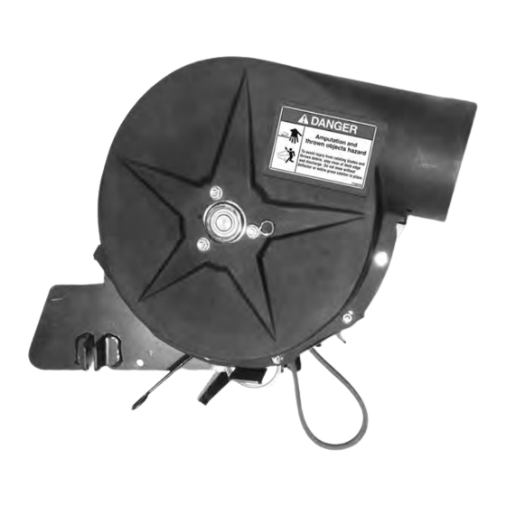
Parts / Hardware - PULLEY ASSEMBLY, (Qty. 1) -TURBO ASSEMBLY, (Qty. 1) - PULLEY COVER, (Qty. 1) HARDWARE BAG 1756733 - CARRIAGE BOLT, - RETAINER, - SNAPPER PIN, .3125” -18 x 1.25, (Qty. 1) .3125”, (Qty. 1) (Qty. 2) - FLAT WASHER, - LOCKWASHER, - KNOB, .3125”, (Qty. -
Page 6: Assembly
Assembly 7. For ease of disassembly in Step 8, wedge a wooden WARNING block between the mower blade and the mower deck housing to keep the mower blade from turning (Figure Before beginning any service work turn off the PTO, set the parking brake, turn off the ignition, and disconnect the spark plug wire(s). -
Page 7: Install Turbo Assembly
Install Turbo Assembly 6. On the inside of discharge opening, insert carriage bolt (B, Figure 7) through slot and secure with retainer (C). 1. Park tractor on a hard, level surface such as a concrete floor. Engage parking brake, disengage PTO, and stop engine. -
Page 8: Install New Pulley Cover
9. On right side, align holes of deck tab (o, Figure 9) with 12. Ensure belt is routed as shown in Figure 11. holes of turbo tabs (p) and secure with snapper pin (F). 10. On left side, pull back on idler arm (n). Align holes of deck tab with holes of turbo tabs and secure with snapper pin. -
Page 9: Operation
Operation Before Operation Clear the lawn of all sticks, stones, wire and other debris which may be caught or thrown by the mower blades. For best results, mow when the grass is dry. Wet grass tends to clump and plug up the mower and grass catcher For efficient grass collection, air circulation under the mower deck, through the chute and into the grass catcher or cart is very important. -
Page 10: Turbo Removal
Turbo Removal 6. On left side, remove snapper pins (F, Figure 16) from DANGER deck tabs (o) and turbo tabs (p). To operate without the collection system, the turbo 7. On left side, pull back on idler arm (n). Align holes assembly MUST be removed and the deflector MUST be of deck tab with holes of turbo tabs and secure with in the down position. -
Page 11: Storage
Storage 9. Align notches of old pulley cover (D, Figure 18) with Storage holes in deck plate (a). Tighten tapetites. Remove any debris from the turbo housing. To clean the housing, use a mild detergent only (other products may damage tube). If paint has been scratched on metal parts, touch up with paint, or apply a thin film of oil. -
Page 12: Warranty
Warranty BRIGGS & STRATTON PRODUCTS WARRANTY POLICY APRIL 2012 LIMITED WARRANTY Briggs & Stratton warrants that, during the warranty period specified below, it will repair or replace, free of charge, any part that is defective in material or workmanship or both. Transportation charges on product submitted for repair or replacement under this warranty must be borne by purchaser. This warranty is effective for and is subject to the time periods and conditions stated below.