Table of Contents
Advertisement
Quick Links
INSTALLATION MANUAL
AIR
CONDITIONER
Please read this installation manual completely before installing the product.
Installation work must be performed in accordance with the national wiring standards
by authorized personnel only.
Please retain this installation manual for future reference after reading it thoroughly.
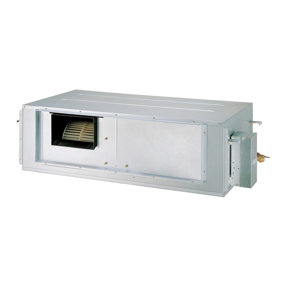
Multi V Fresh Air Intake Unit
Original instruction
MFL67475722
Rev.01_122022
Copyright © 2012 - 2022 LG Electronics Inc. All Rights Reserved.
www.lg.com
Advertisement
Table of Contents

Related Manuals for LG Multi V ARNU48GBRZ Series


Summary of Contents for LG Multi V ARNU48GBRZ Series
- Page 1 Installation work must be performed in accordance with the national wiring standards by authorized personnel only. Please retain this installation manual for future reference after reading it thoroughly. Multi V Fresh Air Intake Unit Original instruction www.lg.com MFL67475722 Copyright © 2012 - 2022 LG Electronics Inc. All Rights Reserved. Rev.01_122022...
-
Page 2: Table Of Contents
TABLE OF CONTENTS TABLE OF CONTENTS FEATURES SAFETY PRECAUTIONS INSTALLATION Installation Limit Selection of the best location Ceiling dimension and hanging bolt location Indoor Unit Installation Wiring Connection Check the Drainage Indoor Unit Drain Piping DIP Switch Setting of Indoor unit PCB Group Control Setting Model Designation Airborne Noise Emission... -
Page 3: Features
Features Features Air outlet vents Air filters Air intake vents Wired Remote Controller (Optional) Standard Accessories Washer for Clamp Insulation for Name Clamp metal Drain hose hanging bracket (Tie Wrap) fitting Others Quantity 1 EA 2 EA 8 EA 4 EA 1 SET •... -
Page 4: Safety Precautions
Safety Precautions Safety Precautions To prevent injury to the user or other people and property damage, the following instructions must be followed. n Be sure to read before installing the air conditioner. n Be sure to observe the cautions specified here as they include important items related to safety. n Incorrect operation due to ignoring instruction will cause harm or damage. - Page 5 Safety Precautions • Use a vacuum pump or Inert (nitrogen) gas when do leakage test or air purge. Do not compress air or Oxygen and do not use Flammable gases. Otherwise, it may cause fire or explosion. - There is the risk of death, injury, fire or explosion. •...
-
Page 6: Installation
Installation Installation Installation Limit Read completely, then follow step by step. 1. Fresh Air Intake Unit Combination Connection Condition Combination System only includes Fresh Air 1) The total capacity of all Fresh Air Intake Units should Intake Units be 50 to 100% of outdoor unit. 1) The total capacity index of all indoor units must be 50 to 100% of the outdoor unit capacity. - Page 7 Installation 3. Installation of intake air duct Min. 2m Inlet Hood 1/30 Slope Intake Air Duct Outlet Air Fresh Air Intake Unit Exhaust Fan Door Exhaust air ① Inlet Hood Inlet Hood should be installed such that no water enter inside the unit ②...
- Page 8 Standard 48 kBtu/h 48 kBtu/h 48 kBtu/h 48 kBtu/h ZONE 1 ZONE 2 5. Cycle check and SVC For Fresh Intake Unit cycle check and SVC, LG MV 5.8 or later version should be used. 8 Fresh Air Intake Unit...
-
Page 9: Selection Of The Best Location
Installation Selection of the best location Install the air conditioner in the location that satisfies the following conditions. • The place shall easily bear a load exceeding four times the indoor unit’s weight. • The place shall be able to inspect the unit as the figure. •... -
Page 10: Ceiling Dimension And Hanging Bolt Location
Installation Ceiling dimension and hanging bolt location n Installation of Unit BR Chassis (48k) Install the unit above the ceiling correctly. CASE 1 POSITION OF SUSPENSION BOLT • Apply a joint-canvas between the unit and duct to absorb unnecessary vibration. (Unit:mm) Dimension Capacity(Btu/h) -
Page 11: Indoor Unit Installation
Installation Indoor Unit Installation • Select and mark the position for fixing bolts. • Insert the set anchor and washer onto the • Drill the hole for set anchor on the face of ceiling. suspension bolts for locking the suspension bolts on the ceiling. -
Page 12: Check The Drainage
Installation INSULATION, OTHERS Insulate the joint and tubes completely. THERMAL INSULATION All thermal insulation must comply with local requirement. INDOOR UNIT Union for liquid pipe Thermal insulator for refrigerant pipe (Local supply) Thermal insulator for Refrigerant pipe and thermal piping(Local supply) insulator(Local supply) Hose crip for thermal insulator (Local supply) -
Page 13: Indoor Unit Drain Piping
Installation CAUTION 1. Install declination of the indoor unit is very important for the drain of the duct type air conditioner. 2. Minimum thickness of the insulation for the connecting pipe shall be 5mm. Front of view • The unit must be horizontal or declined to the drain hose connected when finished installation. Ceiling Drain Pump Drain Pump... - Page 14 Installation CAUTION After the confirmation of the above conditions, prepare the wiring as follows: 1) Never fail to have an individual power specialized for the air conditioner. As for the method of wiring, be guided by the circuit diagram posted on the inside of control box cover. 2) Provide a circuit breaker switch between power source and the unit.
-
Page 15: Dip Switch Setting Of Indoor Unit Pcb
Installation DIP Switch Setting of Indoor unit PCB Function Description Setting Off Setting On Default Communication N/A (Default) Cycle N/A (Default) Group Control Selection of Master or Slave Master Slave Selection of Dry Contact Dry Contact Mode Wired/Wireless remote Mode controller Auto Selection of Manual or Auto... -
Page 16: Group Control Setting
Installation Group Control Setting 1. Group Control 1 Wired remote controller 1 + Standard Indoor Units LGAP Network System Slave Master Slave Signal Slave 12 V Display Error Message Only connect serial signal and GND lines between slave indoor unit Master DIP Switch in PCB (Cassette and Duct Type indoor units) - No. - Page 17 Installation 5. In case of any error occurs at indoor unit, display on the wired remote controller. Exception of the error indoor unit, an individual indoor unit control possibility. 6. In case of Group Control, it is possible to use following functions. - Selection of operation options (operation/stop/mode/set temperature) - Control of flow rate (High/Middle/Low) - It is not possible at some functions.
- Page 18 Installation 3. Group Control 3 Mixture connection with indoor units and Fresh Air Intake Unit LGAP Network System Signal Master Slave Master Slave 12 V Display Error Message Master Master In case of connecting with standard indoor unit and Fresh Intake Unit, separate Fresh Air Intake Unit with standard units.
- Page 19 Installation 4. 2 Remote Control Wired remote controller 2 + Indoor unit 1 LGAP Network System Master Display Error Message Master Slave 1. It is possible to connect two wired remote controllers with one indoor unit. 2. Every types of indoor unit is possible to connect two remote controller. 3.
-
Page 20: Model Designation
Installation Model Designation Serial Number Combinations of functions A:Basic function L: Neo Plasma(Wall Mounted) C: Plasma(Ceiling Cassette) G: Low Static K: High Sensible Heat U: Floor Standing without Case SE/S8 - R: Mirror V: Silver B:Blue(ART COOL Type Panel Clolr) - E: Red V: Silver G:Gold 1: Kiss (Photo changeable) -
Page 21: Outlet Air Temp & Air Flow Rate
Outlet Air Temp & Air flow rate Outlet Air Temp & Air flow rate 1. Outlet Air Temperature ARNU48GBRZ* Cooling Outdoor 59 WB 63 WB 69 WB 73 WB 79 WB 82 WB 86 WB 90 WB 95 WB air temperature 32.0 10.4 12.9... - Page 22 Outlet Air Temp & Air flow rate Cooling 59 WB 63 WB 69 WB 73 WB 79 WB 82 WB 86 WB 90 WB 95 WB Outdoor air temperature 32.0 11.9 11.4 11.1 14.8 10.8 14.4 18.2 10.7 14.1 17.9 20.7 13.7 17.6...
- Page 23 Outlet Air Temp & Air flow rate ARNU96GB8Z* Cooling 59 WB 63 WB 69 WB 73 WB 79 WB 82 WB 86 WB 90 WB 95 WB Outdoor air temperature 32.0 11.1 10.3 16.0 10.6 15.3 10.6 10.5 14.8 10.0 20.5 14.3 11.2...
- Page 24 Outlet Air Temp & Air flow rate 2. Air flow rate ARNU48GBRZ* ESP (mmAq) Setting Value 15.8 18.7 22.2 19.9 13.6 24.2 23.4 17.8 25.2 24.1 19.6 26.8 25.5 21.9 15.9 28.1 22.8 18.2 10.6 19.8 13.8 30.3 28.5 22.5 15.8 29.8 26.5...
- Page 25 İTHALATÇI FİRMA Arçelik-LG Klima Sanayi ve Ticaret A.Ş. Merkez Adresi : Gebze Organize Sanayi Bölgesi, İhsan Dede Cad. No: 139, 41480 Gebze Kocaeli Telefonu : (0262) 678 78 78 Telefaksı : (0262) 678 78 79 ÜRETİCİ FİRMA LG Electronics Inc...