LG MULTI V 2 Series Installation Manual
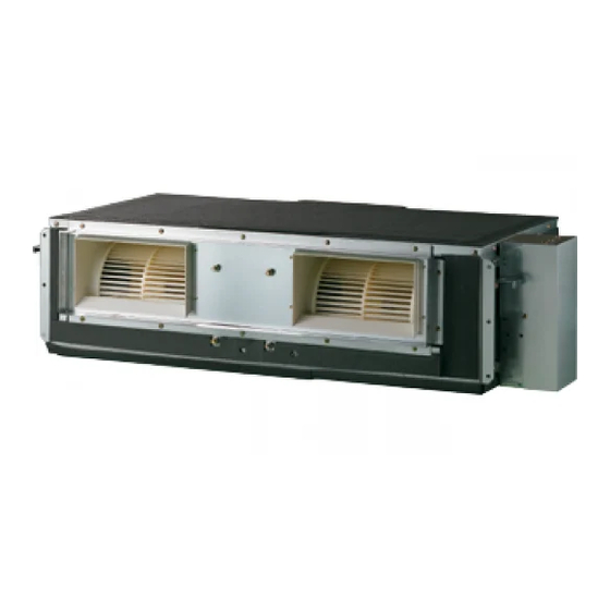
System indoor unit, type: ceiling concealed duct - high static
Hide thumbs
Also See for MULTI V 2 Series:
- Installation manual (100 pages) ,
- Installation manual (20 pages) ,
- Installation manual (17 pages)
Table of Contents
Advertisement
Available languages
Available languages
Indoor Unit (2 Series)
INSTALLATION MANUAL
Type: Ceiling Concealed Duct - High Static
System
IMPORTANT
• Please read this installation manual completely before
installing the product.
• Installation work must be performed in accordance with
the national wiring standards by authorized personnel
only.
• Please retain this installation manual for future reference
after reading it thoroughly.
LG
Advertisement
Chapters
Table of Contents

Related Manuals for LG MULTI V 2 Series


Summary of Contents for LG MULTI V 2 Series
- Page 1 System Indoor Unit (2 Series) INSTALLATION MANUAL Type: Ceiling Concealed Duct - High Static IMPORTANT • Please read this installation manual completely before installing the product. • Installation work must be performed in accordance with the national wiring standards by authorized personnel only.
-
Page 2: Table Of Contents
Ceiling Concealed Duct - High Static Type Indoor Unit Installation Manual TABLE OF CONTENTS Required Parts Required Tools Installation Requirements Features ........3 Safety Precautions ....4 Installation Level gauge Four type "A" screws Screw driver Connecting cable Electric drill Selection the best location ..7 Hole core drill Ceiling opening dimension Pipes: Gas side... -
Page 3: Features
Feature Features Air outlet vents Air filters Air intake vents Wired Remote Controller TE MP ote Cont roller Installation Manual 3... -
Page 4: Safety Precautions
Safety Precautions Safety Precautions To prevent injury to the user or other people and property damage, the following instructions must be followed. Be sure to read before installing the air conditioner. Be sure to observe the cautions specified here as they include important items related to safety. Incorrect operation due to ignoring instruction will cause harm or damage. - Page 5 Safety Precautions Do not modify or extend the Do not let the air conditioner Be cautious when unpacking power cable. run for a long time when the and installing the product. humidity is very high and a door or a window is left open. •...
- Page 6 Safety Precautions Installation Always check for gas (refriger- Install the drain hose to ensure Keep level even when installing ant) leakage after installation or that water is drained away prop- the product. repair of product. erly. • Low refrigerant levels may cause •...
-
Page 7: Installation
Installation Installation Read completely, then follow step by step. Selection of the best location Install the air conditioner in the location that satisfies the following conditions. • The place shall easily bear a load exceeding four times the indoor unit’s weight. •... - Page 8 Installation Ceiling dimension and hanging bolt location BH/BG/BR Chassis Installation of Unit Install the unit above the ceiling correctly. CASE 1 POSITION OF SUSPENSION BOLT • Apply a joint-canvas between the unit and duct to absorb unnecessary vibration. (Unit:mm) Dimension Capacity(Btu/h) 7/9/12/15/18/24k 932 28/36/42k...
-
Page 9: Indoor Unit Installation
Installation Indoor Unit Installation • Select and mark the position for fixing bolts. • Insert the set anchor and washer onto the suspen- • Drill the hole for set anchor on the face of ceiling. sion bolts for locking the suspension bolts on the ceiling. -
Page 10: Checking The Drainage
Installation INSULATION, OTHERS Insulate the joint and tubes completely. THERMAL INSULATION All thermal insulation must comply with local requirement. INDOOR UNIT Union for liquid pipe Thermal insulator for refrigerant pipe (Local supply) Thermal insulator for Refrigerant pipe and thermal piping(Local supply) insulator(Local supply) Hose crip for thermal insulator (Local supply) - Page 11 Installation CAUTION 1. Install declination of the indoor unit is very important for the drain of the duct type air conditioner. 2. Minimum thickness of the insulation for the connecting pipe shall be 5mm. Front of view • The unit must be horizontal or declined to the drain hose connected when finished installation.
- Page 12 Installation CAUTION: After the confirmation of the above conditions, prepare the wiring as follows: 1) Never fail to have an individual power specialized for the air conditioner. As for the method of wiring, be guided by the circuit diagram posted on the inside of control box cover. 2) Provide a circuit breaker switch between power source and the unit.
- Page 13 Installation Installation of Wired Remote Controller 1. Connect the wired remote controller cable to the wired remote controller installation board as shown in the right picture. 12V SIG GND Red wire Yellow Yellow wire Black Black wire Remote Controller Cable The wired remote controller cable is connected as factory default.
- Page 14 Installation 5. Use the connecting cable to connect the indoor unit and the wired remote controller. Check whether the connector is connected correctly. Indoor unit side Connecting cable 6. When the distance between the wired remote controller and the indoor unit is 10m and above, use the extension cable.
-
Page 15: Optional Operation Of Wired Remote Controller
Optional Operation of Wired Remote Controller Optional Operation of Wired Remote Controller Two Thermistor System 1. Press button for 4 seconds to enter the installer setting mode until timer segment display “01:01”. 2. Repeat pressing button to select Function code 04. 04:01 Function Code Thermistor setting... -
Page 16: How To Set E.s.p
How to Set E.S.P? How to Set E.S.P? What is an E.S.P function? This is the function that decides the strength of the wind for each wind level and because this function is to make the installation easier, please do not use this function when using the remote controller. If you set ESP incorrectly, the air conditioner may malfunction. - Page 17 How to Set E.S.P? ARNU07GBHA2, ARNU09GBHA2, ARNU12GBHA2 ARNU15GBHA2, ARNU18GBHA2, ARNU24GBHA2 (Unit: CMM) Static Pressure(mmAq(Pa)) Setting Value 3(30) 4(40) 5(50) 6(60) 7(70) 8(80) 9(90) 10(100) 12(120) 10.7 13.4 11.2 15.9 13.2 12.6 10.3 18.6 16.2 15.2 12.8 11.1 19.8 18.8 18.0 15.3 14.2 12.4...
- Page 18 How to Set E.S.P? URNU76GB8A2, URNU96GB8A2 Static Pressure(mmAq) Setting Value 25(250) 40.5 52.7 63.7 47.1 71.1 56.9 44.7 76.3 69.7 55.2 83.3 78.6 67.4 55.9 89.7 87.1 78.9 67.6 54.2 93.4 91.4 86.1 66.4 50.6 93.4 91.4 88.3 84.9 75.9 69.5 60.8 43.1...
- Page 19 Type: Ceiling Concealed Duct-High Static IMPORTANTE IMPORTANT • Leggere questo manuale d’istruzioni prima di installare il condizionatore d’aria. • Il lavoro d’installazione deve essere eseguito conformemente alla normativa vigente sugli impianti elettrici, solo da personale tecnico autorizzato. • Dopo averlo letto dettagliatamente, conservare questo manuale come riferimento per il futuro...
- Page 20 Unità interna con pompa di calore Manuale d'installazione SOMMARIO Componenti Arnesi richiesti Lavori di installazione dell’installazione Installazione Componeti..3 Precauzioni di siculezza ..4 Installazione Vitie tasselli in plastica Livella Cavo di collegamento Cacciavite Scelta del posizionamento più Trapano elettrico indicato ........7 Trapano per carotaggio Dimensioni apertura soffitto e Tubi: lato gas...
-
Page 21: Installazione Componeti
Installazione Componeti Installazione Componeti Bocchette di erogazione aria Filtri aria Bocchette di aspirazione aria TE MP Dispositivo di regolazione ote Cont roller Manuale Installazione 3... -
Page 22: Precauzioni Di Siculezza
Precauzioni di sicurezza Precauzioni di sicurezza Rispettare le seguenti istruzioni per prevenire infortuni agli utenti, e alle altre persone in generale, e danni alle proprietà. Assicurarsi di aver letto le istruzioni prima di installare il condizionatore d’aria. Osservare le avvertenze specificate qui perché riguardano aspetti importanti attinenti alla sicurezza. Operazioni errate dovute alla non osservanza delle istruzioni possono causare lesioni o danni. - Page 23 Precauzioni di sicurezza Non utilizzare interruttori automatici Non utilizzare il prodotto troppo a Il prodotto deve essere sempre difettosi o di potenza inferiore. lungo in ambienti molto umidi e con provvisto di messa a terra. Utilizzare questa apparecchiatura su una finestra o una porta aperta. un circuito dedicato.
- Page 24 Precauzioni di sicurezza ATTENZIONE Installazione Dopo l'installazione o la riparazione del Installare il tubo flessibile di scarico Installare il prodotto allineandolo in prodotto, verificare sempre che non vi in modo da garantire uno scarico cor- modo uniforme. siano perdite di gas (refrigerante). retto e sicuro.
-
Page 25: Installazione
Installazione Installazione Scelta del posizionamento più indicato Installare il condizionatore in un punto che soddisfi i seguenti requisiti: • Il punto del soffitto dove viene montata l’unità deve essere in grado di reggere un carico quattro volte supe- riore al peso della stessa unità. •... - Page 26 Installazione Dimensioni apertura soffitto e posizionamento bulloni di sospensione Installazione dell’unità BH/BG/BR Chassis Installare l’unità correttamente sopra il soffitto. ESEMPIO 1 POSIZIONE DEL BULLONE DI SOSPENSIONE • Inserire del materiale assorbente tra l’unità e il con- dotto per smorzare le vibrazioni. •...
-
Page 27: Sospensione
Installazione Installazione unità interna Nuova Vecchia costruzione costruzione 1 Ancoraggio 2 Rondella piana 3 Rondella elastica 4 Dado 5 Bulloni di sospensione • Stabilire e contrassegnare la posizione dei bulloni • Inserire l’ancoraggio e la rondella sui bulloni di di fissaggio. sospensione per bloccare i bulloni sul soffitto. -
Page 28: Controllo Dello Scarico
Installazione ISOLAMENTO, VARIE Isolare completamente il raccordo e i tubi. ISOLAMENTO TERMICO Il tipo di isolamento termico adottato deve essere conforme agli stan- dard locali. UNITÀ INTERNA Tubo liquido refrig. ed elem. termoisolante(a carico dell’utente) Attacco per tubo liquido refrig. Elem. - Page 29 Installazione AVVERTENZA 1. La giusta inclinazione dell’unità interna è molto importante per lo scarico dei condizionatori di questo tipo. 2. Lo spessore minimo dell’isolamento per il tubo di collegamento deve essere 5mm. Vista anteriore • L’unità deve essere montata in piano o leggermente inclinata verso il tubo flessibile di scarico collegato.
- Page 30 Installazione AVVERTENZA : Dopo aver realizzato le suddette condizioni, preparare i fili elettrici secondo le seguenti istruzioni: 1) Utilizzare sempre un circuito di alimentazione dedicato esclusivamente al condizionatore. Per quanto riguarda il metodo di collegamento, seguire lo schema riportato all’interno del coperchietto quadro di comando.
-
Page 31: Installazione Dispositivo Di Regolazione
Installazione Installazione dispositivo di regolazione 1. Collegare il cavo del telecomando alla scheda di installazione dello stesso come mostrato nella figura a destra. 12V SIG GND Filo rosso Arancione Giallo Filo giallo Nero Filo nero Cavo del telecomando Il cavo del telecomando è collegato per impostazione predefinita. 2. - Page 32 Installazione 5. Utilizzare il cavo di collegamento per collegare l'unità interna e il telecomando. Verificare che il connettore sia collegato correttamente. Lato unità interna Cavo di collegamento 6. Quando la distanza tra il telecomando cablato e l’unità interna è uguale o maggiore di 10 metri, utilizzare una prolunga.
-
Page 33: Optional Operation Of Wired Remote Controller
Sistema a due termistori Optional Operation of Wired Remote Controller Sistema a due termistori 1. Premere per 4 secondi per aprire la modalità di impostazione fino alla visualizzazione di '01:01 2. Premere ancora per selezionare il codice funzione 04:01 Codice funzione Impostazione termistore 3. -
Page 34: Impostazione Installatore -E.s.p
Impostazione installatore -E.S.P. Impostazione installatore -E.S.P. Cosa è una funzione E.S.P? Questa è la funzione che decide l'intensità della ventilazione per ciascun livello di ventilazione e poiché la funzione è quella di facilitare l'installazione, non usare la funzione quando si usa il telecomando. ATTENZIONE Se si imposta ESP in modo scorretto, il condizionatore d'aria potrebbe non funzionare in modo corretto. - Page 35 Impostazione installatore -E.S.P. ARNU07GBHA2, ARNU09GBHA2, ARNU12GBHA2 ARNU15GBHA2, ARNU18GBHA2, ARNU24GBHA2 (Unit: CMM) Pressione statica(mmAq) Valore impostazione 3(30) 4(40) 5(50) 6(60) 7(70) 8(80) 9(90) 10(100) 12(120) 10.7 13.4 11.2 15.9 13.2 12.6 10.3 18.6 16.2 15.2 12.8 11.1 19.8 18.8 18.0 15.3 14.2 12.4 10.4...
- Page 36 Impostazione installatore -E.S.P. URNU76GB8A2, URNU96GB8A2 Pressione statica(mmAq) Valore impostazione 25(250) 40.5 52.7 63.7 47.1 71.1 56.9 44.7 76.3 69.7 55.2 83.3 78.6 67.4 55.9 89.7 87.1 78.9 67.6 54.2 93.4 91.4 86.1 66.4 50.6 93.4 91.4 88.3 84.9 75.9 69.5 60.8 43.1 93.2...
- Page 37 Type: Ceiling Concealed duct-High Static IMPORTANTE • Lea este manual de instrucciones completamente antes de instalar el producto. • El trabajo de instalación debe realizarse de acuerdo con el Reglamento Eléctrico nacional y únicamente por personal autorizado. • Después de leer completamente este manual de instalación, guárdelo para futuras consultas.
- Page 38 Aire acondicionado de Tipo Duto Manual de instalación ÍNDICE Trabajos de instalación Componentes de instalación Herramientas necesarias Instalación componentes..3 Precauciones de seguidad ..4 Instalación Nivel Cuatro tornillos modelo "A" & Destornillador Selección de la ubicación fijaciones de plástico Taladro eléctrico perfecta........7 Cable de conexión Broca...
-
Page 39: Instalación Componentes
Instalación Componentes Instalación Componentes Rejillas de salida de aire Filtros de aire Rejillas de entrada de aire Control remoto TE MP ote Cont roller Manual de Instalación 3... -
Page 40: Precauciones De Seguidad
Precauciones de seguridad Precauciones de seguridad Para evitar lesiones al usuario o a otras personas y daños materiales, debe seguir las siguientes instrucciones. Lea estas instrucciones antes de instalar el aire acondicionado. Observe las precauciones especificadas en este manual, ya que incluyen indicaciones importantes relacionadas con la seguridad. - Page 41 Precauciones de seguridad No modifique ni extienda el cable No deje funcionando el aire Tenga cuidado al desembalar e de alimentación. acondicionado durante mucho instalar el aparato. tiempo cuando la humedad sea muy alta y haya una puerta o ventana abierta. •...
- Page 42 Precauciones de seguridad PRECAUCIÓN Instalación Compruebe siempre las fugas de Instale la manguera de drenaje para Instale el aparato bien nivelado. gas (refrigerante) después de la asegurarse de que el agua se drena instalación o reparación del correctamente. aparato. • Niveles bajos de refrigerante pueden •...
-
Page 43: Instalación
Instalación Instalación Selección de la ubicación perfecta Instale el aparato acondicionador de aire en el lugar que cumpla las condiciones que se indican a continuación. • El lugar puede soportar con facilidad una carga que exceda el cuádruple del peso de la unidad interior. •... -
Page 44: Dimensiones Del Techo Y Situación Del Perno De Suspensión
Instalación Dimensiones del techo y situación del perno de suspensión Instalación de la unidad Instale la unidad correctamente en el techo. CASE 1 POSITION OF SUSPENSION BOLT • Aplique una tela de unión entre la unidad y el conducto para absorber las vibraciones innecesarias. -
Page 45: La Instalación De La Unidad Interior
Instalación La instalación de la unidad interior • Seleccione y marque la posición para los pernos • Inserte el anclaje de fijación y la arandela en los de sujeción. pernos de suspensión para fijar los pernos de • Taladre el orificio para el anclaje de fijación en el suspensión en el techo. -
Page 46: Comprobación Del Drenaje
Instalación AISLAMIENTO, OTROS Aísle completamente la unión y los conductos. AISLAMIENTO TÉRMICO Todo aislamiento térmico debe cumplir los requisitos locales. UNIDAD INTERIOR Aislador térmico para tubería de líquido refrigerante. (Suministro local) Unión para tubería de líquido Aislamiento local para tuberías Tubería de líquido refrigerante y (Suministro local) aislante térmico (suministro local) - Page 47 Instalación PRECAUCIÓN 1. La inclinación de instalación de la unidad interior es muy importante para el drenaje del aparato acondicionador de aire con conductos. 2. El grosor mínimos del aislante para el tubo conector será de 5 mm. Vista frontal •...
- Page 48 Instalación PRECAUCIÓN : Una vez confirmadas las condiciones anteriores, prepare el cableado como sigue: 1) Nunca deje de tener una corriente individual especial para el aire acondicionado. Con respecto al método de cableado, siga los pasos del diagrama de circuito colocado en el interior de la cubierta de control.
-
Page 49: Instalación Del Mando A Distancia
Instalación Instalación del mando a distancia 1. Conecte el cable del controlador a distancia a la placa de instalación correspondiente, como ilustra la imagen derecha. 12V SIG GND Cable rojo Rojo Amarillo Cable amarillo Negro PUESTA A TIERRA Cable negro Cable del controlador a distancia El cable del controlador a distancia está... - Page 50 Instalación 5. Utilice el cable de conexión para conectar la unidad interior y el controlador a distancia. Compruebe si el conectar está correctamente conectado. Lado de la unidad interior Cable de conexión 6. Cuando la distancia entre el controlador a distancia alámbrico y la unidad interior sea de 10 m o más, utilice una alargadera.
-
Page 51: Optional Operation Of Wired Remote Controller
Doble sistema térmico Optional Operation of Wired Remote Controller Sistema de dos resistencias 1. Presione durante 4 segundos para introducir el modo de configuración del instalador hasta que el segmento del temporizador muestre "01:01". 2. Vuelva a presionar para seleccionar el código de función 04. -
Page 52: Configuración Del Instalador -E.s.p
Configuración del instalador –E.S.P. Configuración del instalador –E.S.P. ¿Qué es una función E.S.P.? Esta función decide la potencia del flujo de aire en cada nivel, y como su finalidad es facilitar la instalación, no la utilice junto con el mando a distancia. PRECAUCIÓN Si ajusta incorrectamente la función ESP, el aire acondicionado podría funcionar mal. - Page 53 Configuración del instalador –E.S.P. ARNU07GBHA2, ARNU09GBHA2, ARNU12GBHA2 ARNU15GBHA2, ARNU18GBHA2, ARNU24GBHA2 (Unit: CMM) Presión estática (mm A) Valor de ajuste 3(30) 4(40) 5(50) 6(60) 7(70) 8(80) 9(90) 10(100) 12(120) 10.7 13.4 11.2 15.9 13.2 12.6 10.3 18.6 16.2 15.2 12.8 11.1 19.8 18.8 18.0...
- Page 54 Configuración del instalador –E.S.P. URNU76GB8A2, URNU96GB8A2 Presión estática (mm A) Valor de ajuste 25(250) 40.5 52.7 63.7 47.1 71.1 56.9 44.7 76.3 69.7 55.2 83.3 78.6 67.4 55.9 89.7 87.1 78.9 67.6 54.2 93.4 91.4 86.1 66.4 50.6 93.4 91.4 88.3 84.9 75.9...
- Page 55 Type: Gainable(High-Static) IMPORTANT • Veuillez lire entièrement ce manuel d’instructions avant d'installer le matériel. • Conformément aux standards nationaux sur le câblage, l’installation ne doit être effectuée que par du personnel autorisé. • Après l’avoir lu entièrement, veuillez conserver ce manuel d’installation pour référence ultérieure.
- Page 56 Type Gainable (High-Static) Manuel d'installation TABLE DES MATIÈRES Eléments à installer Outillage Travaux d'installation Eléments d'installation ..3 Mesures de sécurité....4 Installation Niveau à bulle Quatre vis de type "A" Tournevis Choix du meilleur emplace- Plaque de montage Perceuse électrique ment........7 Embout scie trépan Longueur horizontale Dimension du plafond et...
-
Page 57: Eléments D'installation
Eléments d'installation Eléments d'installation Grilles de sortie d’air Filtres d’air Grilles d’entrée d’air Commande à distance TE MP ote Cont roller Manuel d'installation 3... -
Page 58: Mesures De Sécurité
Mesures de sécurité Mesures de sécurité Les instructions ci-après doivent être observées dans le but de prévenir tout risque de dommages corporels ou matériels. Veillez à lire ce manuel avant d’installer le climatiseur. Veillez à observer les précautions spécifiées dans ce manuel, puisqu’elles incluent des points importants con- cernant la sécurité. - Page 59 Mesures de sécurité Ne modifiez ni prolongez le cordon Ne laissez pas le climatiseur Prenez soin lorsque vous déballez d'alimentation. marcher trop longtemps lorsque et installez ce produit. l'humidité est très élevée et qu'il y a une porte ou une fenêtre ouverte. •...
- Page 60 Mesures de sécurité ATTENTION Installation Vérifiez toujours s'il y a des fuites Installez le raccord de drainage de Maintenez le produit de niveau lors de gaz (frigorigène) suite à l'instal- manière à assurer une vidange de son installation. lation ou réparation du produit. appropriée.
-
Page 61: Installation
Installation Installation Choix du meilleur emplacement Installez le climatiseur dans un emplacement ayant les caractéristiques suivantes : • Il devra supporter aisément un poids quatre fois plus lourd que le poids de l’unité intérieure. • L’unité devra être placée dans un endroit où elle puisse être révisée facilement, comme il est illustré sur la figure. - Page 62 Installation Dimension du plafond et emplacement des boulons de support Installation de l’unité BH/BG/BR Chassis Installez correctement l’unité au dessus du plafond. CAS 1 POSITION DU BOULON DE SUPPORT • Utilisez un joint en étoupe entre l’unité et le conduit afin d’absorber toute vibration inutile.
-
Page 63: Support
Installation Installation de l’unité intérieure • Choisissez et marquez la position des boulons de • Insérez l’élément d’ancrage et la rondelle dans les fixation. boulons de support pour fixer les boulons de sup- • Percez le trou d’ancrage au plafond. port au plafond. -
Page 64: Vérification Du Drainage
Installation ISOLATION, AUTRES Isolez complètement les joints et les tubes. ISOLATION THERMIQUE Toute isolation thermique doit respecter les régulations locales. UNITÉ INTÉRIEURE Isolant thermique pour tuyau réfrigérant (Fourniture sur place) Joint pour le tuyau à liquide Isolant thermique pour tuyauterie Tuyau réfrigérant et isolant thermique (Fourniture sur place) (Fourniture sur place) - Page 65 Installation ATTENTION 1. L’installation en pente de l’unité intérieure est très importante pour le drainage du climatiseur du type conduit. 2. L’épaisseur minimale de l’isolation pour le tuyau de connexion devra être de 5 mm. Vue du front • L’unité doit être horizontalement ou inclinée vers le raccord de drainage à la fin de l’installation.
- Page 66 Installation ATTENTION: Après confirmation des conditions ci-dessus, préparez le câblage comme suit : 1) Assurez-vous de disposer d’un circuit individuel destiné exclusivement au climatiseur. Quant à la méthode de câblage, suivez le schéma de circuit collé à l’intérieur du couvercle du panneau de commande.
-
Page 67: Installation De La Commande À Distance
Installation Installation de la commande à distance 1. Connectez le câble de la télécommande à la carte d’installation de la télécommande à fil comme sur l’image de droite. 12V SIG GND Fil rouge Rouge Jaune Fil jaune Noir Fil noir Câble de la Télécommande Le câble de la télécommande est connecté... - Page 68 Installation 5. Utilisez le câble de connexion pour reliser l’unité intérieure et la télécommande. Vérifiez que le connecteur soit bien branché. Côté unité intérieure Câble de connexion 6. Si la distance entre la télécommande à fil et l’unité intérieure est de 10 mètres ou plus, utilisez une rallonge.
-
Page 69: Optional Operation Of Wired Remote Controller
Système à deux thermistors Optional Operation of Wired Remote Controller Système à deux thermistors 1. Pour entrer au mode de réglage d’installation, appuyez sur la touche pendant 4 secondes jusqu’à ce que le segment minuteur affiche « 01:01 ». 2. Appuyez plusieurs fois sur la touche pour sélectionner le code de fonction 04. -
Page 70: Paramètres De L'installateur - E.s.p
Paramètres de l’installateur – E.S.P. Paramètres de l’installateur – E.S.P. Qu’est ce que la function E.S.P. ? Cette fonction gère la puissance de ventilation pour chaque niveau de ventilation. Cette fonction ren- dant l’installation beaucoup plus facile, veuillez ne pas utiliser cette dernière lorsque vous utilisez la télécommande. - Page 71 Paramètres de l’installateur – E.S.P. ARNU07GBHA2, ARNU09GBHA2, ARNU12GBHA2 ARNU15GBHA2, ARNU18GBHA2, ARNU24GBHA2 (Unité: CMM) Static Pressure(mmAq) Valeur de réglage 3(30) 4(40) 5(50) 6(60) 7(70) 8(80) 9(90) 10(100) 12(120) 10.7 13.4 11.2 15.9 13.2 12.6 10.3 18.6 16.2 15.2 12.8 11.1 19.8 18.8 18.0 15.3...
- Page 72 Paramètres de l’installateur – E.S.P. URNU76GB8A2, URNU96GB8A2 Static Pressure(mmAq) Valeur de réglage 25(250) 40.5 52.7 63.7 47.1 71.1 56.9 44.7 76.3 69.7 55.2 83.3 78.6 67.4 55.9 89.7 87.1 78.9 67.6 54.2 93.4 91.4 86.1 66.4 50.6 93.4 91.4 88.3 84.9 75.9 69.5...
- Page 73 Type: Ceiling Concealed Duct-High Static WICHTIG • Lesen Sie diese Anleitung vor der Montage des Gerätes vollständig durch. • Die Montage darf nur durch qualifiziertes Personal und muss gemäß den nationalen Bestimmungen für elektrische Anschlüsse erfolgen. • Bewahren Sie dieses Benutzerhandbuch nach dem Lesen zum späteren Gebrauch an einem sicheren Ort auf.
- Page 74 Kassetten-Klimaanlag Montageanleitung INHALTSVERZEICHNIS Installationsteile Benötigtes Werkzeug Arbeitsvorgänge Installationsteile .....3 Sicherheitshinweise....4 Installierung Niveau Vir Schrauben Typ "A" und Schraubenzieher Auswahl des besten Standorts Duebel Elektrischer Bohrer ..........7 Verbindungskabel Wandbohre Wasserwage Abmessungen Deckenöffnung Leitungen: Gasseite Lötwerkzeugsatz und Position Aufhängung ..8 Flüssigkeitsseite Gegenhalteschlüssel Isolierter Abflussch lauch (different depending on model No.) Weiterer Abflupsch lauch...
-
Page 75: Installationsteile
Installationsteile Installationsteile Luftauslassöfnungen Luftfilter Luftauslassöfnungen Fernbedienung TE MP ote Cont roller Montageanleitung 3... -
Page 76: Sicherheitshinweise
Sicherheitshinweise Sicherheitshinweise Um Verletzungen des Benutzers oder anderer Personen sowie Sachbeschädigungen zu vermeiden, müssen die folgenden Anleitungen befolgt werden. Lesen Sie vor der Montage des Raum-Klimagerätes dieses Handbuch sorgfältig durch. Beachten Sie angegebene Vorsichtshinweise mit wichtigen sicherheitsrelevanten Informationen. Ein unsachgemäßer Betrieb bei Missachtung von Anleitungen führt zu Verletzungen oder Beschädigungen.Die Schweregrade werden durch folgende Symbole gekennzeichnet. - Page 77 Sicherheitshinweise Netzkabel nicht verändern oder Das Klimagerät sollte bei extrem hoher Das Gerät vorsichtig auspacken und verlängern. Luftfeuchtigkeit oder bei geöffneten montieren. Türen/Fenstern nicht lange betrieben werden. • Es besteht Feuer- oder Stromschlaggefahr. • Feuchtigkeit könnte kondensieren und • Scharfe Kanten bergen Verletzungsgefahr. Möbel befeuchten oder beschädigen Besonders auf Gehäusekanten und Lamellen des Kondensators und...
- Page 78 Installation VORSICHT Installation Nach der Montage oder Reparatur des Ablassschlauch zum ordnungs- Das Gerät immer waagerecht mon- Gerätes immer auf Gaslecks (Kältemit- gemäßen Wasserabfluss montieren. tieren. tel) überprüfen. • Ein niedriger Kältemittelstand kann zum • Mangelhafte Verbindungen können • So werden Vibrationen oder Wasserlecks Ausfall des Gerätes führen.
-
Page 79: Installierung
Installierung Installierung Auswahl des besten Standorts Montieren Sie das Klimagerät an einer Position, die folgenden Anforderungen genügt. • Die Position muss problemlos eine Last tragen können, die dem vierfachen des Gewichts der Inneneinheit entspricht. • Die Position muss zur Inspektion so zugänglich sein, wie in der Abbildung dargestellt. •... -
Page 80: Und Position Aufhängung
Installierung Abmessungen Deckenöffnung und Position Aufhängung Montage der Einheit BH/BG/BR Chassis Montieren Sie die Einheit korrekt über der Decke. FALL 1 POSITION DER AUFHANGUNGSSCHRAUBE • Montieren Sie einen Segeltuchstutzen zwischen Einheit und Kanal um die Übertragung der Vibrationen zu verhindern •... -
Page 81: Installation Der Inneneinheit
Installierung Installation der Inneneinheit • Wählen und markieren Sie die Position für die • Setzen Sie die Dübel und Scheiben auf die Befestigungsschrauben. Aufhängungsbolzen, um diese an der Decke zu • Bohren Sie das Loch für die befestigen. Verankerungsschraube in die Decke. •... -
Page 82: Prüfen Des Abflusses
Installierung DAMMUNG, ANDERE Dämmen Sie die Verbindungsstelle und die Leitungen WARMEDAMMUNG Die gesamte Wärmedämmung muss den örtlichen Vorschriften entsprechen. Inneneinheit Verschraubung für Schlauchklemme für Wärmedämmung (Bauseitig) Wärmedämmung für Wärmedämmung für Kältemittelleitung (Bauseitig) Kältemittelleitung (Bauseitig) Kältemittelleitung und Wärmedämmung (bauseitig) Überlappung mit Wärmedämmung Wärmedämmung für für Leitung. - Page 83 Installierung VORSICHT 1. Die Montageneigung der Inneneinheit ist sehr wichtig für den Ablauf des Kanaleinbaugeräts. 2. Die minimale Dicke der Dämmung für die Verbindungsleitung sollte 7 mm betragen. Vorderansicht • Die Einheit muss nach dem Abschluss der Installation waagerecht oder in Richtung des Kondensatschlauchs geneigt sein.
- Page 84 Installierung VORSICHT: Bereiten Sie, nach der Überprüfung der obigen Bedingungen die Verkabelung wie folgt vor: 1) Schließen Sie das Klimagerät immer an einen eigenen Stromkreis an. Beachten Sie für die Verkabelung das Elektroschema auf der Innenseite der Abdeckung des Steuergehäuses. 2) Montieren Sie einen Sicherung zwischen Hauptnetz und der Einheit.
-
Page 85: Installation Der Fernbedienung
Installierung Installation der Fernbedienung 1. Schließen Sie das Kabel der Fernbedienung an die Anschlussplatine der Kabel-Fernbedienung, wie in der Abbildung rechts gezeigt. 12V SIG GND Roter Draht Gelber Draht Gelb Schwarz Schwarzer Draht Kabel der Fernbedienung Das Kabel der Fernbedienung ist werkseitig angeschlossen. 2. - Page 86 Installation 5. Schließen Sie das Innengerät über das Anschlusskabel an die Fernbedienung an. Überprüfen Sie, ob die Anschlüsse fest sitzen. Innenge- räteseite Anschlusskabel 6. Bei einem Abstand zwischen der Kabel-Fernbedienung und dem Innengerät von mehr als 10 m muss ein Verlängerungskabel verwendet werden. VORSICHT Die Kabel-Fernbedienung darf nicht in die Wand eingelassen werden.
-
Page 87: Optional Operation Of Wired Remote Controller
Zwei-Thermistor-System Optional Operation of Wired Remote Controller Zwei-Thermistor-System 1. Halten Sie die Taste vier Sekunden lang gedrückt, um den Einstellungsmodus aufzurufen und die Anzeige "01:01" erscheint. 2. Drücken Sie mehrmals die Taste , um Funktionskennung 04 aufzurufen 04:01 Funktionskennung Thermistor-Einstellung 3. -
Page 88: Einstellungsmodus - Esp (Externer Statischer Druck Der Rohrleitung)
Einstellungsmodus - ESP (Externer statischer Druck der Rohrleitung) Einstellungsmodus - ESP (Externer statischer Druck der Rohrleitung) Was ist die ESP-Funktion? Mit Hilfe dieser Funktion wird die Stärke der einzelnen Luftströme geregelt. Diese Funktion soll die Montage vereinfachen und sollte daher nicht bei Verwendung der Fernbedienung eingesetzt werden. VORSICHT Eine unsachgemäße Einstellung des externen statischen Drucks der Rohrleitungen kann Fehlfunktionen des Klimagerätes verursachen. - Page 89 Einstellungsmodus - ESP (Externer statischer Druck der Rohrleitung) ARNU07GBHA2, ARNU09GBHA2, ARNU12GBHA2 ARNU15GBHA2, ARNU18GBHA2, ARNU24GBHA2 (Einheit: CMM) Statischer Druck(mmAq(Pa)) Einstellung 3(30) 4(40) 5(50) 6(60) 7(70) 8(80) 9(90) 10(100) 12(120) 10.7 13.4 11.2 15.9 13.2 12.6 10.3 18.6 16.2 15.2 12.8 11.1 19.8 18.8 18.0...
- Page 90 Installation URNU76GB8A2, URNU96GB8A2 Statischer Druck(mmAq(Pa)) Einstellung 25(250) 40.5 52.7 63.7 47.1 71.1 56.9 44.7 76.3 69.7 55.2 83.3 78.6 67.4 55.9 89.7 87.1 78.9 67.6 54.2 93.4 91.4 86.1 66.4 50.6 93.4 91.4 88.3 84.9 75.9 69.5 60.8 43.1 93.2 91.3 88.3 84.9...
- Page 91 P/No.: MFL42803104 Printed in Korea After reading this manual, keep it in a place easily accessible to the user for future reference.