Table of Contents
Advertisement
Available languages
Available languages
Quick Links
TABLE OF CONTENTS
****************
General Safety Rules .......................2-3
Specific Safety Rules ......................... 3
Symbols ..............................................4
Electrical ..........................................5-6
Features ...........................................7-8
Tools Needed ..................................... 8
Loose Parts ...................................9-10
Assembly .....................................11-18
Operation .....................................19-25
Adjustments ................................26-28
Maintenance ................................29-30
Warranty ...........................................31
Parts Ordering/Service ....... Back Page
WARNING:
To reduce the risk of injury, the user
must read and understand the op-
erator's manual before using this
product.
SAVE THIS MANUAL FOR
FUTURE REFERENCE
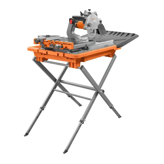
8 in. TILE AND PAVER SAW WITH LASER
SCIE À CARREAUX ET PAVES SOUS EAU
TABLE DES MATIÈRES
****************
Règles de sécurité générales ..........2-3
Règles de sécurité particulières ......... 4
Symboles ............................................5
Caractéristiques électriques ............6-7
Caractéristiques ..............................8-9
Outils nécessaires .............................. 9
Pièces détachées ........................10-11
Assemblage .................................12-19
Utilisation .....................................20-26
Réglages ......................................27-29
Entretien ......................................30-31
Garantie ............................................32
Commande de pièces /
réparation ..........................Page arrière
AVERTISSEMENT :
Pour réduire les risques de blessures,
l'utilisateur doit lire et veiller à bien
comprendre le manuel d'utilisation
avant d'utiliser ce produit.
CONSERVER CE MANUEL
POUR FUTURE RÉFÉRENCE
OPERATOR'S MANUAL
MANUEL D'UTILISATION
MANUAL DEL OPERADOR
DE 203 mm (8 po) AVEC LASER
SIERRA PARA LOSAS Y PAVIMENTO
DE 203 mm (8 pulg.) CON LÁSER
register.ridgidpower.com
Pour enregistrer votre produit de
RIDGID, s'il vous plaît la visite :
register.ridgidpower.com
Para registrar su producto de
register.ridgidpower.com
ÍNDICE DE CONTENIDO
Reglas de seguridad generales .......2-3
Reglas de seguridad especificas ....... 4
Símbolos ............................................5
Aspectos eléctricos .........................6-7
Características ................................8-9
Herramientas necesarias .................. 10
Piezas sueltas ..............................10-11
Armado ........................................12-19
Funcionamiento ...........................20-26
Ajustes .........................................27-29
Mantenimiento .............................30-31
Garantía ............................................32
Pedidos de piezas/
servicio .......................... Pág. posterior
ADVERTENCIA:
Para reducir el riesgo de lesiones, el
usuario debe leer y comprender el
manual del operador antes de usar
este producto.
GUARDE ESTE MANUAL
PARA FUTURAS CONSULTAS
R4041/R4041S
To register your RIDGID
product, please visit:
RIDGID, por favor visita:
****************
Advertisement
Table of Contents

Related Manuals for RIDGID R4041


Summary of Contents for RIDGID R4041
-
Page 1: Table Of Contents
DE 203 mm (8 pulg.) CON LÁSER R4041/R4041S To register your RIDGID product, please visit: register.ridgidpower.com Pour enregistrer votre produit de RIDGID, s’il vous plaît la visite : register.ridgidpower.com Para registrar su producto de RIDGID, por favor visita: register.ridgidpower.com TABLE OF CONTENTS TABLE DES MATIÈRES... -
Page 2: General Safety Rules
GENERAL SAFETY RULES SECURE WORK. Use clamps or a vise to hold work when practical, it is safer than using your hand and frees both WARNING: hands to operate the tool. Read and understand all instructions. Failure to DON’T OVERREACH. Keep proper footing and balance follow all instructions listed below, may result in at all times. -
Page 3: Specific Safety Rules
GENERAL SAFETY RULES INSPECT TOOL CORDS PERIODICALLY. If damaged, STAY ALERT AND EXERCISE CONTROL. Watch what have repaired by a qualified service technician at an you are doing and use common sense. Do not operate authorized service facility. The conductor with insulation tool when you are tired. -
Page 4: Symbols
SYMBOLS The following signal words and meanings are intended to explain the levels of risk associated with this product. SYMBOL SIGNAL MEANING Indicates a hazardous situation, which, if not avoided, will result in death or DANGER: serious injury. Indicates a hazardous situation, which, if not avoided, could result in death or WARNING: serious injury. -
Page 5: Electrical
ELECTRICAL ELECTRICAL CONNECTION EXTENSION CORDS Use only 3-wire extension cords that have 3-prong This tool is powered by a precision built electric motor. It should be connected to a power supply that is 120 V, AC grounding plugs and 3-pole receptacles that accept the tool’s only (normal household current), 60 Hz. - Page 6 ELECTRICAL If the saw is used with an extension cord, ensure the connection of the tool’s power cord and the extension cord are not on the ground. If a GFCI protected outlet is not available, do not use the saw until an outlet can be changed or auxiliary protection can be obtained.
-
Page 7: Features
FEATURES PRODUCT SPECIFICATIONS Wheel diameter ............8 in. Diagonal capacity (tile size) ........18 in. Wheel arbor .............. 5/8 in. Maximum depth of cut .......... 2-3/4 in. Rip cut capacity (plank tile) ......up to 48 in. Rating ...........120 V~, 12 Amps, 60 Hz No load speed .........4,400 /min (RPM) DEPTH STOP LOCK KNOB... -
Page 8: Tools Needed
FEATURES KNOW YOUR TILE SAW WARNING: See Figure 3. The safe use of this product requires an understanding of Making bevel cuts at angles other than 0˚, 22.5˚, the information on the tool and in this operator’s manual as and 45˚ angles could cause the cutting wheel to well as a knowledge of the project you are attempting. -
Page 9: Loose Parts
LOOSE PARTS The following items are included with your tile saw stand: A - Stand ................1 B - Height adjustment pin ..........4 Fig. 5 9 — English... - Page 10 LOOSE PARTS The following items are included with your tile saw: Fig. 6 K - Water tray ..............1 A - Motor head assembly ..........1 L - Water filter ..............1 B - Hex key (6 mm) ............1 M - Cap screw ..............4 C - Wheel wrench ............1 D - Arbor nut ..............1 N - Water pump ..............1...
-
Page 11: Assembly
ASSEMBLY UNPACKING ASSEMBLING THE STAND See Figures 5 - 6. See Figures 7 - 8. This product requires assembly. With the unit in the upright position, spread the legs of the stand. Place stand on level ground. Carefully lift the parts from the carton and place on a level work surface. - Page 12 ASSEMBLY To adjust the height of the stand, move each adjustable foot up or down until the hole in the leg is aligned with one of the holes in the foot. Secure the feet in place using height adjustment pins with bales. NOTE: Make sure the feet are positioned at the same height to ensure stability.
- Page 13 ASSEMBLY WATER INSTALLING WATER FILTER AND WATER WATER TRAY FILTER PUMP See Figures 10 - 11. PUMP WELL The water pump recirculates water from the tray to the cutting wheel. Locate filter slots and pump well in water tray. Pump well is marked “pump well.”...
- Page 14 ASSEMBLY INSTALLING THE FRAME Lift the edge of the frame and attach the water hose to the pump elbow. See Figure 12. Rest the pump power cord and water hose in the notches Carefully lift the frame assembly over the water tray, as provided on the water tray.
- Page 15 ASSEMBLY INSTALLING THE SLIDING TABLE LOCK TABLE LOCK See Figure 14. LEVER To install the sliding table: UNLOCK Grasp the table firmly and set the rear rollers on the front of rails. Holding the table parallel with the frame, push the table toward the back of the saw.
- Page 16 ASSEMBLY Attaching rear splash guard: Loosen wheel guard knob by turning counterclockwise and open the cutting wheel guard. Line up rear splash guard holes with screw hole and post Place the wheel wrench on the arbor nut then slide the on back of cutting wheel guard, as shown.
- Page 17 ASSEMBLY TRAY TAB INSTALLING WATER TRAY EXTENSION WATER FRAME TRAY See Figure 19. Standing at the back of the saw, hold the water tray ex- TRAY TAB tension with the tray tabs toward the slots. Tilt the tray and slip the tray tabs between the frame top and frame bottom.
- Page 18 ASSEMBLY INSTALLING THE MITER GUIDE MITER GUIDE See Figure 22. TO LOOSEN The miter guide can be used from either the left or right side of the cutting wheel. MITER GUIDE NOTE: The miter guide cannot be installed until the drop KNOB fence is in the raised position.
-
Page 19: Operation
OPERATION SWITCH WARNING: SWITCH Do not allow familiarity with tools to make you careless. Remember that a careless fraction of a second is sufficient to inflict serious injury. WARNING: Always wear eye protection with side shields marked to comply with ANSI Z87.1 along with PADLOCK hearing and breathing protection. - Page 20 OPERATION LOCKING/UNLOCKING THE MOTOR HEAD FOR PLUNGE CUTS See Figure 25. To unlock and raise the motor head: Firmly grasp the “D” handle and apply downward pressure while at the same time turning the motor head lock knob counterclockwise. ...
- Page 21 OPERATION CROSS CUT NOTE: Laser may be difficult to see in bright sunlight. With the wheel in the cutting position, move the tile until the mark and the laser line are aligned. MITER MARK Make several practice cuts on different styles and thickness GUIDE of material.
- Page 22 OPERATION DIAGONAL CUT Let the cutting wheel build up to full speed and wait for the wheel to get wet before moving the material into the wheel. Hold the material firmly against the rip fence and slowly feed the material into the cutting wheel. ...
- Page 23 OPERATION TO MAKE AN L-CUT Slide the saw table to the front of the water tray before tilting the saw head. See Figure 31. Loosen the bevel lock knob. L-cuts are cuts that remove a piece of tile to fit in a corner, around a cabinet, or a piece of molding and are made by ...
- Page 24 OPERATION Turn the on/off switch to the on position. Turn the on/off switch to the on position. Let the cutting wheel build up to full speed and wait for Let the cutting wheel build up to full speed and wait for the wheel to get wet before moving the material into the the wheel to get wet before moving the material into wheel.
- Page 25 OPERATION Move the sliding table away from the motor head and turn paver over to make through cut. To make paver for corners: Measure paver and landscaping feature to determine how much material needs to be removed and how much of an angle is required for wall corner.
-
Page 26: Adjustments
ADJUSTMENTS WARNING: Before performing any adjustment, make sure the tool is unplugged from the power supply and the switch is in the OFF position. Failure to heed this warning could result in serious personal injury. The saw has been adjusted at the factory for making very accurate cuts. - Page 27 ADJUSTMENTS LOWER CAM ROLLER TO ADJUST SLIDING TABLE ADJUSTMENT See Figures 41 - 42 . SET SCREW If the table doesn’t slide smoothly, seems too loose on the SELF-SETTING rails, moves side to side, or is visibly off track adjustments BOLT may be required.
- Page 28 ADJUSTMENTS POSITIVE STOP ADJUSTMENTS See Figure 44. NOTE: These adjustments were made at the factory and normally do not require readjustment. Unplug the saw. If the wheel is not perfectly vertical (0°): Loosen the bevel lock knob. Raise the motor head. ...
-
Page 29: Maintenance
MAINTENANCE BRUSH REPLACEMENT WARNING: See Figure 46. When servicing, use only identical RIDGID The saw motor has externally accessible brush assemblies replacement parts. Use of any other parts can that should be periodically checked for wear. create a hazard or cause product damage. - Page 30 MAINTENANCE CLEANING THE RAILS CLEANING THE SUBMERSIBLE PUMP During use, the rails will become dirty preventing the table Unplug pump before handling or cleaning the pump. rollers from rolling smoothly. Be sure to wash off and wipe Remove the front cover. clean the rails often.
-
Page 31: Warranty
RIDGID , Inc. All warranty communications should be neglect, alteration, modification or repair by other than ® directed to TTI Consumer Power Tools, Inc., attn: RIDGID an authorized service center for RIDGID branded hand ® ®... -
Page 32: Règles De Sécurité Générales
RÈGLES DE SÉCURITÉ GÉNÉRALES PORTER UNE TENUE APPROPRIÉE. Ne pas porter de vêtements amples, cravates, ou bijoux susceptibles de AVERTISSEMENT : se prendre et vous entraîner dans les pièces mobiles. Des Lire et veiller à bien comprendre toutes les gants en caoutchouc et des chaussures antidérapantes instructions. - Page 33 RÈGLES DE SÉCURITÉ GÉNÉRALES PORTER UNE PROTECTION AUDITIVE. Porter une prolongateurs à 3 fils doté d’une fiche à prise de terre protection auditive durant les périodes d’utilisation branchés sur une prise triphasée compatible avec la fiche prolongée. de l’outil. ...
-
Page 34: Règles De Sécurité Particulières
RÈGLES DE SÉCURITÉ PARTICULIÈRES TOUJOURS ASSUJETTIR LA PIÈCE À COUPER Les avertissements ci-dessous doivent être apposés sur CET OUTIL : fermement contre le guide d’onglet ou le guide. NE JAMAIS se tenir ou laisser une partie du corps se trouver a) Porter une protection oculaire, auditive et respiration. -
Page 35: Symboles
SYMBOLES Les termes de mise en garde suivants et leur signification ont pour but d’expliquer le degré de risques associé à l’utilisation de ce produit. SYMBOLE SIGNAL SIGNIFICATION Indique une situation dangereuse qui, si elle n’est pas évitée, aura pour DANGER : conséquences des blessures graves ou mortelles. -
Page 36: Caractéristiques Électriques
CARACTÉRISTIQUES ÉLECTRIQUES CORDONS PROLONGATEURS AVERTISSEMENT : Utiliser exclusivement des cordons prolongateurs à 3 fils doté d’une fiche à prise de terre branchés sur une prise triphasée Vérifier l’état des cordons prolongateurs avant chaque compatible avec la fiche de l’outil. Lors de l’utilisation d’un utilisation. - Page 37 CARACTÉRISTIQUES ÉLECTRIQUES Consulter un électricien qualifié ou le personnel de service si les instructions de mise à la terre ne sont pas bien comprises, ou en cas de doute au sujet de la mise à la terre. Tout cordon endommagé doit être réparé ou remplacé immédiatement.
-
Page 38: Caractéristiques
CARACTÉRISTIQUES FICHE TECHNIQUE Diamètre de la meule........203 mm (8 po) Capacité de diagonale ( carreaux la taille ) ... 457 mm (18 po) Arbre de la meule ........15,8 mm (5/8 po) Profondeur de coupe maximum ....70 mm (2-3/4 po) Alimentation nominale ......120 V~, 12 A, 60 Hz Capacité... -
Page 39: Outils Nécessaires
CARACTÉRISTIQUES POUR SE FAMILIARISER AVEC LA SCIE À AVERTISSEMENT : CARREAUX Voir la figure 3. Les coupes en biseau n’étant pas faites aux angles de 0, 22,5 et 45° peuvent provoquer le contact de la meule L’utilisation sûre de ce produit exige une compréhension des à... -
Page 40: Pièces Détachées
PIÈCES DÉTACHÉES Les composants suivants sont inclus avec votre support pour scie à carreaux : A - Support ..............1 B - Axe de réglage de hauteur ........4 Fig. 5 10 — Français... - Page 41 PIÈCES DÉTACHÉES Les composants suivants sont inclus avec votre scie à carreaux : Fig. 6 A - Ensemble du moteur de tête ........1 K - Plateau d’eau ............1 L - Filtre à eau ..............1 B - Clé hex. (6 mm) ............1 M - Boulon de capuchon ..........4 C - Clé...
-
Page 42: Assemblage
ASSEMBLAGE DÉBALLAGE ASSEMBLAGE DU SUPPORT Voir les figures 5. et 6 Voir les figures 7 et 8. Ce produit doit être assemblé. En plaçant l’appareil en position verticale, déployer les pattes du support. Déposer le stand sur un sol à niveau. ... - Page 43 ASSEMBLAGE Pour ajuster la hauteur du support, déplacer chaque pied réglable vers le haut ou le bas jusqu’à ce que le trou de la patte soit aligné avec l’un des trous du pied. Sécuriser la position de du pied en utilisant les axe de réglage de hauteur. NOTE : S’assurer que les pieds sont positionnés à...
- Page 44 ASSEMBLAGE INSTALLATION DU FILTRE À EAU ET DE LA FILTRE PLATEAU D’EAU À EAU POMPE À EAU CUVETTE DE Voir les figures 9 et 11. LA POMPE La pompe permet de réacheminer l’eau du plateau à la coulé sur la meule. Repérer les fentes du filtre et de la cuvette de la pompe situées dans plateau d’eau.
- Page 45 ASSEMBLAGE INSTALLATION DE LA CADRE Soulever le rebord du cadre et fixer le tuyau d’arrosage au coude de la pompe. Voir la figure 12. Faire reposer le cordon d’alimentation de la pompe et de Soulever délicatement du cadre sur le plateau d’eau, comme boyau d’eau dans les encoches situées sur le plateau d’eau.
- Page 46 ASSEMBLAGE INSTALLATION DES TABLE COULISSSANTE VERROUILLEZ LEVIER DE Voir la figure 14. VERROUILLAGE DE Pour installer de table coulissante : TABLE Tenir fermement la table et installer les rouleaux à l’avant des rails. DÉVERROUILLEZ Tenir l e parallèle de table avec le bâti, pousser la table vers arrière du scie.
- Page 47 ASSEMBLAGE Fixation du pare-éclaboussures arrière : Verrouiller la table en position avant. Dévisser le boulon du protège-meule en le tournant vers la Aligner les trous du pare-éclaboussures avec le trou de vis gauche et ouvrir le protège-meule. et le montant situés à...
- Page 48 ASSEMBLAGE INSTALLATION PLATEAU D’EAU L’EXTENSION CADRE ONGLET DE PLATEAU PLATEAU D’EAU Voir la figure 19. Depuis l’arrière de la scie, aligner la rallonge du plateau d’eau ONGLET DE PLATEAU et les onglets du plateau en direction des fentes. Incliner le plateau et glisser les onglets du plateau entre le haut et le bas du cadre.
- Page 49 ASSEMBLAGE INSTALLATION GUIDE D’ONGLET GUIDE Voir la figure 22. D’ONGLET POUR DESSERRER Le guide d’onglet peut être utilisé de la gauche et de la droit du côté de la meule de coupe. BOUTON DU GUIDE NOTE : Le guide d’onglet ne peut pas être installé tant que le D’ONGLET guide de dénivellation se trouve en position levée.
-
Page 50: Utilisation
UTILISATION COMMUTATEUR EN COMMUTATEUR POSITION D’ARRÊT EN POSITION AVERTISSEMENT : DE MARCHE Ne pas laisser la familiarité avec l’outil faire oublier la prudence. Ne pas oublier qu’une fraction de seconde d’inattention peut entraîner des blessures graves. AVERTISSEMENT : Toujours porter une protection oculaire avec écrans latéraux certifiée conforme à... - Page 51 UTILISATION VERROUILLAGE / DÉVERROUILLAGE DU MOTEUR DE TÊTE POUR COUPES PLONGEANTE Voir la figure 25. Pour déverrouiller et relever le moteur de tête : Tenir fermement la poignée en D et appuyer vers le bas tout en tournant simultanément le bouton de verrouillage de la BOUTON DE tête du moteur vers la gauche.
- Page 52 UTILISATION COUPE TRANSVERSALE fonction, il génère une ligne rouge sur la surface de travail. Le pointillé permet de voir la marque tracée sur le carreaux en GUIDE DE même temps que le trait laser ce qui permet d’aligner les deux MARQUER DÉNIVELLATION lignes afin d’obtenir une coupe plus précise.
- Page 53 UTILISATION COUPE EN DIAGONALE Placer le matériau sur la table et fermement contre le guide de dénivellation. Avant d’allumer la scie, s’assurer que le matériaux ne touche pas la meule à carreaux. Mettre le commutateur marche/arrêt en position de marche. ...
- Page 54 UTILISATION POUR EFFECTUER UNE COUPE EN L COUPE EN L Voir la figure 31. Une coupe en L est une section de la matériaux q’on retire et qu’on utilize lorsqu’on coupe un morceau de matériaux afin de l’ajuster dans le coin d’une armoire ou une boiserie et sont fait par deux coupures séparées.
- Page 55 UTILISATION COUPE PLONGEANTE Placer le matériau sur la table et fermement contre le guide d’onglet et guide ou la guide longitudinal. S’assurer que le matériau ne touche pas la meule avant de démarrer la scie. Mettre le commutateur marche/arrêt en position de marche. ...
- Page 56 UTILISATION Laissez le meule de coupe atteindre son régime maximum et attendre le meule pour obtenir mouillé avant d’avancer le matériau pour alimenter la pièce vers le meule. Maintenir la matériaux fermement contre le guide d’onglet et guide, et engager le meule de coupe. ...
-
Page 57: Réglages
RÉGLAGES AVERTISSEMENT : Avant d’effectuer tout réglage, s’assurer que l’outil est débranché et que son commutateur est en position d’arrêt (OFF). Le non-respect de cet avertissement pourrait entraîner des blessures graves. Cette scie à table a été réglée en usine pour effectuer des coupes très précises. - Page 58 RÉGLAGES RÉGLAGES DE LA TABLE COULISSANTE RÉGLAGE DU ROULEAU À CAME INFÉRIEUR Voir les figures 41 et 42. BOULON À VIS D’ARRÊT Si la table ne glisse pas en douceur, semble branlante dans ses INSTALLATION rails ou est déraillée, des ajustements s’imposent. AUTOMATIQUE Pour ajuster si la table est desserrer : ...
- Page 59 RÉGLAGES RÉGLAGES DE BUTÉE POSITIVE Voir la figure 44. NOTE : Ces réglages ont été effectués en usine et n’ont normalement pas besoin d’être refaits. Débrancher la scie. Si la meule n’est pas parfaitement verticale (0°) : Desserrer le bouton de verrouillage de biseau. ...
-
Page 60: Entretien
AVERTISSEMENT : Voir la figure 46. Le moteur de la scie est équipé de balais accessibles de Utiliser exclusivement des pièces RIDGID identiques à l’extérieur, dont l’usure doit être vérifiée périodiquement. celles d’origine pour les réparations. L’usage de toute autre pièce pourrait créer une situation dangereuse Lorsque le remplacement des balais s’avère nécessaire,... - Page 61 ENTRETIEN NETTOYER DE RAILS NETTOYAGE DE LA POMPE Pendant l’usage, la rails deviendra empêcher sale les rouleaus Débrancher la pompe avant de la manipuler ou de la nettoyer. de table du glissement facilement. C’est important de nettoyer Retirer le couvercle avant. la rails souvent.
-
Page 62: Garantie
à un usage particulier ne pouvant pas être exclues en raison des lois en vigueur, sont limitées Cette garantie sur les outils motorisés à main et d’établi RIDGID ® à une durée de trois ans, à compter de la date d’achat. TTI couvre tous les vices de matériaux et de fabrication, ainsi que les... -
Page 63: Reglas De Seguridad Generales
REGLAS DE SEGURIDAD GENERALES VÍSTASE ADECUADAMENTE. Evite ponerse ropas holgadas, corbatas ni joyas que puedan engancharse y tirar ADVERTENCIA: de usted hacia las piezas en movimiento. Se recomiendan Lea y comprenda todas las instrucciones. El guantes y calzado antiderrapantes (botes de goma) al incumplimiento de las instrucciones señaladas abajo trabajar al aire libre. - Page 64 REGLAS DE SEGURIDAD GENERALES PROTÉJASE EL OÍDO. Durante períodos prolongados de USE SOLAMENTE LOS DISPOSITIVOS ELÉCTRICOS CORRECTOS: cables de extensión de 3 conductores, con utilización de la unidad póngase protección para los oídos. clavijas de tres puntas y contactos de tres polos que acepten ...
-
Page 65: Reglas De Seguridad Especificas
REGLAS DE SEGURIDAD ESPECÍFICAS ASEGURE LA PIEZA DE TRABAJO firmemente contra guía SIEMPRE APAGUE LA SIERRA antes de desconectarla, de ingletes o la guía. para evitar un arranque accidental de la misma al volver a conectarla al suministro de corriente. ... -
Page 66: Símbolos
SÍMBOLOS Las siguientes palabras de señalización y sus significados tienen el objeto de explicar los niveles de riesgo relacionados con este producto. SÍMBOLO SEÑAL SIGNIFICADO Indica una situación peligrosa, la cual, si no se evita, causará la muerte o lesiones PELIGRO: serias. -
Page 67: Aspectos Eléctricos
ASPECTOS ELÉCTRICOS CABLES DE EXTENSIÓN ADVERTENCIA: Sólo utilice cables de extensión de 3 conductores con clavijas de tres puntas y contactos de tres polos que acepten la clavija Inspeccione los cables de extensión cada vez antes del cable de la herramienta. Si la herramienta eléctrica debe de usarlos. - Page 68 ASPECTOS ELÉCTRICOS Consulte a un electricista calificado o técnico de servicio si no ha comprendido completamente las instrucciones de conexión a tierra o si no está seguro si la herramienta está bien conectada a tierra. Repare o reemplace de inmediato todo cordón dañado o gastado.
-
Page 69: Características
CARACTERÍSTICAS ESPECIFICACIONES DEL PRODUCTO Diámetro de la hoja ........203 mm (8 pulg.) Capacidad de diagonale (tamaño de losas) ........457 mm (18 pulg.) Árbol de la hoja ........15,8 mm (5/8 pulg.) Profundidad del corte máxima ....70 mm (2-3/4 pulg.) Capacidad de corte al hilo (losa de tablón) ........hasta 121,9 cm (48 pulg.) Potencia nominal ........120 V~, 12 A, 60 Hz... -
Page 70: Herramientas Necesarias
CARACTERÍSTICAS FAMILIARÍCESE CON LA SIERRA DE LOSAS ADVERTENCIA: Vea la figura 3. El uso seguro que este producto requiere la comprensión de la Si realiza cortes en bisel con ángulos que no sean 0˚, información impresa en la herramienta y en el manual del operador 22,5˚... -
Page 71: Piezas Sueltas
PIEZAS SUELTAS Con la para pedestal de sierra de losas vienen incluidos los siguientes artículos: A - Pedestal ..............1 B - Pasador de ajuste de altura ........4 Fig. 5 10 — Español... - Page 72 PIEZAS SUELTAS Con la sierra de losas vienen incluidos los siguientes artículos: Fig. 6 A - Conjunto del motor de cabeza .........1 K - Bandejas de agua .............1 B - Llave hexagonal (6 mm) ..........1 L - Filtro de agua ............1 C - Llave de la muela ............1 M - Tornillo de cabeza hueca ..........4 D - Tuerca del árbol ............1...
-
Page 73: Armado
ARMADO DESEMPAQUETADO ARMADO DEL PEDESTAL Vea las figuras 5 y 6. Voir les figures 7 et 8. Este producto requiere armarse. Con la unidad en posición ascendente, coloque las patas sobre el pedestal. Ubique el pedestal sobre un terreno ... - Page 74 ARMADO Para ajustar la altura del pedestal, mueva cada pie ajustable hacia arriba o hacia abajo hasta que el orificio de la pata quede alineado con uno de los orificios del pie. Asegure los pies en su lugar utilizando los pasadores de ajuste de altura con las correas.
- Page 75 ARMADO INSTALACIÓN DEL FILTRO DE AGUA Y LA FILTRO BANDEJAS DE AGUA BOMBA DE AGUA DE AGUA Vea las figuras 10 y 11. POZO DE LA La bomba causa la recirculación de agua de la bandeja a la hoja. BOMBA Ubique las ranuras para el filtro y el pozo de la bomba dentro de la bandeja de agua.
- Page 76 ARMADO INSTALACIÓN DEL ARMAZÓN Coloque el cable de alimentación de la bomba y la manguera de agua en las muescas provistas para tal fin en la bandeja Vea la figura 12. para el agua. Levante ligeramente el conjunto del marco sobre la bandeja ...
- Page 77 ARMADO INSTALACIÓN DE LAS MESAS DESLIZABLE PALANCA DE ASEGURAR Vea la figura 14. FIJACIÓN DE LA MESA Para instalar la mesa deslizable: DESASEGURAR Sostenga la mesa con firmeza y coloque los rodillos en la parte delantera de los rieles. Sostener la paralela de mesa con el armazón, empuja la mesa hacia parte trasera del sierra.
- Page 78 ARMADO INSTALACIÓN DEL CONJUNTO DEL Desconecte la sierra. PROTECTOR CONTRA SALPICADURAS Fije la mesa en la posición delantera. Vea las figuras 16 a 18. Gire la perilla de la protección de la muela en sentido antihorario para aflojarla y abra la protección de la muela El protector contra salpicaduras de esta sierra es un conjunto de corte.
- Page 79 ARMADO LENGÜETAS DE Inserte el poste, ubicado al costado de la protección de BANDEJAS LA BANDEJA la muela de corte, en el orificio de la solapa lateral de la ARMAZÓN DE AGUA protección. OREJETA DE Acomode las ranuras de la protección contra salpicaduras BANDEJA sobre las costillas de la protección de la muela de corte.
- Page 80 ARMADO CÓMO INSTALAR LA GUÍA DE CORTE GUÍA DE CORTE AL HILO Vea la figura 21. La guía de corte al hilo puede usarse desde el lado izquierdo o derecho del disco de corte. MANGO DE BLOQUEO NOTA: La guía de corte al hilo no puede instalarse hasta que la valla ajustable esté...
-
Page 81: Funcionamiento
FUNCIONAMIENTO INTERRUPTOR EN INTERRUPTOR ADVERTENCIA: POSICIÓN DE ENCENDIDO APAGADO No permita que su familarización con las herramientas lo vuelva descuidado. Tenga presente que un descuido de un instante es suficiente para causar una lesión seria. ADVERTENCIA: Siempre póngase protección ocular con la marca de cumplimiento de la norma ANSI Z87.1, junto con protección auditiva y protección respirar. - Page 82 FUNCIONAMIENTO PROCEDIMIENTO DE TRABA Y DESTRABA EL MOTOR DE CABEZA Vea la figura 25. Para destrabar y levantar el motor de cabeza: Sujete firmemente el mango en “D” y presione hacia abajo mientras tira de la pasador de seguridad hacia afuera, separándola de la carcasa de la sierra.
- Page 83 FUNCIONAMIENTO CORTES TRANSVERSALES propia línea al mismo tiempo, lo cual le ayuda a alinear la marca para lograr un corte más preciso en la losa. NOTA: El láser puede ser difícil de ver si hay mucha luz solar. GUÍA DE INGLETES Manteniendo la sierra hacia arriba, mueva la losa hasta que la MARCA...
- Page 84 FUNCIONAMIENTO CORTE DIAGONALE Asegúrese de que la guía de corte al hilo no esté en la trayectoria de corte. Coloque la materia sobre la mesa y firmemente contra la guía de corte al hilo. Asegúrese de que la material está lejos de la muela para cortar losas antes de encender la sierra.
- Page 85 FUNCIONAMIENTO PARA EFECTUAR CORTES EN L CORTE EN L Vea la figura 31. Une corte en L es una sección que se saca de la material y se una al cortar la material que entrará en un rincón de un mueble o pieza de moldura y son hechos por dos cortes separados.
- Page 86 FUNCIONAMIENTO Asegúrese de que la material está lejos de la muela para Use un marcador o un lápiz de cera para realizar dos marcas; cortar losas antes de encender la sierra. marque todo el contorno del adoquín. Coloque el interruptor de encendido/apagado en la posición ...
- Page 87 FUNCIONAMIENTO Asegúrese de que la material está lejos de la muela para Cuando termine el corte, apague la sierra; para ello, ponga cortar losas antes de encender la sierra. el botón en la posición apagado. Espere a que la muela se detenga por completo antes de retirar cualquier parte de la ...
-
Page 88: Ajustes
AJUSTES ADVERTENCIA: Antes de efectuar cualquier ajuste, asegúrese de que la herramienta esté desconectada del suministro de corriente y de que el interruptor esté en la posición de apagado. La falta de atención a esta advertencia podría causar lesiones corporales graves. La sierra ha sido ajustada en la fábrica para producir cortes muy TORNILLO exactos. - Page 89 AJUSTES REALIZAR AJUSTES SOBRE LA MESA AJUSTE DEL RODILLO DE LEVA INFERIOR PERNO DE DESLIZABLE TORNILLO DE FIJACIÓN ACCIONAMIENTO Vea las figuras 41 y 42. AUTOMÁTICO Si la mesa no desliza lisamente, parece afloja también en la barra de la corredera, o movimientos lado para lado, los ajustes pueden ser requeridos.
- Page 90 AJUSTES AJUSTES DE LOS TOPES Vea la figura 44. NOTA: Estos ajustes se realizaron en la fábrica y normalmente no requieren reajustarse. Desconecte la sierra. Si la muela no está perfectamente vertical (0°): Afloje la perilla de fijación del bisel. ...
-
Page 91: Mantenimiento
Vea la figura 46. Al dar servicio a la unidad, sólo utilice piezas de La sierra dispone de conjuntos de escobillas accesibles repuesto RIDGID idénticas. El empleo de piezas externamente, cuyo desgaste debe revisarse periódica-mente. diferentes puede causar un peligro o dañar el Proceda como sigue cuando se requiera un reemplazo: producto. - Page 92 MANTENIMIENTO LIMPIEZA EL RIEL LIMPIEZA DE LA BOMBA Al usarse, el riel llegará a ser prevenir sucia los rodillos de mesa Desconecte la bomba antes de manipular o limpiar la bomba. de deslizar lisamente. Es importante limpiar el riel a menudo. Retire la tapa delantera.
-
Page 93: Garantía
Se limita a las herramientas de mano y estacionarias RIDGID ® sin ningún costo para el consumidor. adquiridas a partir del 1 de febrero de 2004. Este producto está... - Page 94 NOTES/NOTAS...
- Page 95 NOTES/NOTAS...
- Page 96 TTI CONSUMER POWER TOOLS, INC. P.O. Box 1427 Anderson, SC 29622 USA powertools.ridgid.com 1-866-539-1710 RIDGID is a registered trademark of RIDGID, Inc., used under license. 998000160 6-23-22 (REV:04)