Advertisement
Quick Links
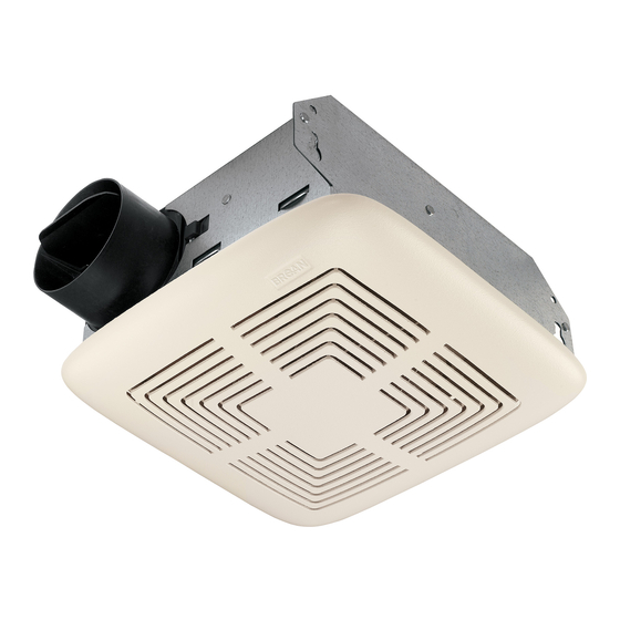
MODEL 771
CEILING/WALL FAN
READ AND SAVE THESE
INSTRUCTIONS
WARNING
TO REDUCE THE RISK OF FIRE, ELECTRIC SHOCK, OR INJURY
TO PERSONS, OBSERVE THE FOLLOWING:
1. Use this unit only in the manner intended by the manufacturer.
If you have questions, contact the manufacturer at the address
or telephone number listed in the warranty.
2. Before servicing or cleaning unit, switch power off at service
panel and lock the service disconnecting means to prevent power
from being switched on accidentally. When the service discon-
necting means cannot be locked, securely fasten a prominent
warning device, such as a tag, to the service panel.
3. Installation work and electrical wiring must be done by a qualified
person(s) in accordance with all applicable codes and standards,
including fire-rated construction codes and standards.
4. Sufficient air is needed for proper combustion and exhausting
of gases through the flue (chimney) of fuel burning equip-
ment to prevent backdrafting. Follow the heating equipment
manufacturer's guideline and safety standards such as those
published by the National Fire Protection Association (NFPA),
and the American Society for Heating, Refrigeration and Air
Conditioning Engineers (ASHRAE), and the local code authorities.
5. When cutting or drilling into wall or ceiling, do not damage
electrical wiring and other hidden utilities.
6. To reduce the risk of fire or electric shock, do not use
with an additional speed control device.
7. Ducted fans must always be vented to the outdoors.
8. Acceptable for use over a bathtub or shower when installed in
a GFCI protected branch circuit.
9. Install fan at least five feet (1.52 m) above the floor.
10. Never place a switch where it can be reached from a tub or shower.
11. This unit must be grounded.
CAUTION
1. For general ventilating use only. Do not use to exhaust hazardous or explosive materials
and vapors.
2. To avoid motor bearing damage and noisy and/or unbalanced impellers, keep drywall
spray, construction dust, etc. off power unit.
3. Please read specification label on product for further information and requirements.
USE AND CARE
DISCONNECT ELECTRIC POWER SUPPLY AND LOCK OUT SERVICE PANEL BEFORE
SERVICING THE UNIT.
PREVENTATIVE MAINTENANCE
A clean fan provides better service. Disconnect the power supply and clean the fan as
described below:
TO CLEAN GRILLE - Use a mild detergent, such as dishwashing liquid, and dry with a soft
cloth. DO NOT USE ABRASIVE CLOTHS, STEEL WOOL PADS, OR SCOURING POWDERS.
TO CLEAN FAN ASSEMBLY - Unplug motor cord from receptacle. To remove motor plate:
Find the single tab on the motor plate (located next to the receptacle). Push up near motor
plate tab while pushing out on side of housing. Or insert a straight-blade screwdriver into
slot in housing (next to tab) and twist screwdriver. Gently vacuum fan, motor and interior
of housing. METAL AND ELECTRICAL PARTS SHOULD NEVER BE IMMERSED IN WATER.
TO REASSEMBLE ALL ABOVE PARTS - Reverse all procedures explained above.
MAINTENANCE
The motor is permanently lubricated and never needs oiling. If the motor bearings are making
excessive or unusual noises, replace the motor with the exact service motor. You should
replace the blower wheel at the same time.
INSTALLATION
1. Push down on plate while pulling out on side of housing. Motor plate may also be removed
by inserting a straight-blade screw driver into slot in housing and twisting screw driver.
(FIG. 1)
2. Remove wiring cover from housing by pulling straight out. Unit is shipped ready to wire
through the top of housing. To wire through the side, bend housing flap to cover top hole
and expose side hole. DO NOT BREAK OFF FLAP. If flap breaks, plug unused hole using
standard electrical hole plug. (FIG. 2)
3. Turn off electrical power at service entrance and connect power cable to housing using
appropriate connector. Wire black to black, white to white, and green to green or bare
wire..
Push all wiring up into corner of unit and replace wiring cover. Make sure cover holds
housing flap in place against side or top of housing.
CAUTION: DO NOT ALLOW WIRES TO EXTEND OUTSIDE OF WIRING BOX. Wire left
exposed will become pinched or cut when motor plate is installed. Electrical shock
may result. (FIG. 3)
4. Choose the location for your fan. For best performance, use the shortest possible duct
run and a minimum number of elbows, For wall installations: Position unit so damper
flap closes when unit is off.
FIG. 1
SCREWDRIVER
SLOT
RANURA PARA
DESARMADOR
FIG. 2
HOUSING
FLAP
SOLAPA DE LA
CAJA
this fan
FIG. 3
SWITCH BOX
CAJA DE
INTERRUPTORES
BLACK
NEGRO
SWITCH OR TIMER
INTERRUPTOR O
REGULADOR
BLACK
NEGRO
120 VAC LINE IN
LINEA DE ENTRADA
A 120 VCA
MODELO 771
VENTILADORE DE TECHO
LEA Y CONSERVE ESTAS
ADVERTENCIA
PARA REDUCIR EL RIESGO DE INCENDIO, DESCARGA ELÉCTRICA,
O LESIONES A PERSONAS, CUMPLA LOS SIGUIENTES PUNTOS:
1. Solamente use esta unidad de la manera propuesta por el fabricante.
Si tiene alguna pregunta, póngase en contacto con el fabricante en
la dirección o teléfono anotados en la garantía.
2. Antes de limpiar o de poner en servicio la unidad, apague el interruptor
en el panel de servicio, y asegure el panel de servicio para evitar que
WIRING
se encienda accidentalmente. Cuando el dispositivo para desconectar
COVER
el servicio eléctrico no puede ser cerrado con algún tipo de traba,
sujete fuertemente al panel de servicio, una etiqueta de advertencia
CUBIERTA DEL
prominente.
ALAMBRADO
3. El trabajo de instalación y el alambrado eléctrico deben llevarse a
cabo por personal calificado de acuerdo con todos los códigos y las
normas aplicables, incluyendo los códigos y normas de construcción
contra incendios.
4. Se requiere una cantidad de aire suficiente para la combustión y escape
de gases por la chimenea del equipo de quemado de combustible
para evitar salirse de las especificaciones y estándares de seguridad
del fabricante, tales como los publicados por la Asociación nacional
de protección contra incendios (NFPA por sus siglas en Inglés), y
la Sociedad americana de ingenieros de calefacción, refrigeración y
aire acondicionado (ASHRAE por sus siglas en Inglés), y los códigos
de las autoridades locales.
5. Cuande corte o taladre en una pared o techo, no dañe los cables
RECEPTACLE
eléctricos ni otras instalaciones ocultas.
RECEPTÁCULO
6. Para reducir el riesgo de incendio o de descarga eléctrica, no utilice
WHITE TO
WHITE
este ventilador con ningún dispositivo de una control de velocidad
BLANCO A
BLANCO
de estado sólido adicional.
7. Los ventiladores con ductos siempre deben de ventilar hacia el exterior.
GREEN TO
GREEN OR
8. Aceptable si se lo usa por encima de una tina o ducha instaladas en
BARE WIRE
VERDE A
WHITE TO
un circuito derivado protegido GFCI (con interruptor accionado por
VERDE 0
WHITE
BLACK TO
ALAMBRE
corriente de pérdida a tierra).
BLANCO A
BLACK
DESNUDO
BLANCO
NEGRO A
9. Instálelo por lo menos a 152 cm sobre el piso.
NEGRO
GROUND
TIERRA
10. NUNCA coloque un interruptor donde pueda ser alcanzado desde
la bañera o la ducha.
11. Esta unidad debe conectarse a tierra.
PRECAUCIÓN
1. Sólo para uso de ventilación general. No se use para extraer materiales o vapores peligrosos
o explosivos.
2. Para evitar daños al cojinete del motor y/o impulsores ruidosos o desequilibrados, mantenga
la fuente de potencia lejos de rocíos de pared seca, de polvo de construcción, etc.
3. Lea la etiqueta de especificaciones en el producto para mayor información y requisitos.
USO Y CUIDADO
DESCONECTE EL SUMINISTRO ELÉCTRICO Y BLOQUEE EL PANEL DE SERVICIO ANTES DE DAR
SERVICIO A LA UNIDAD.
MANTENIMIENTO PREVENTIVO
Un ventilador limpio proporciona mejor servicio. Desconecte el suministro eléctrico y limpie el
ventilador de la siguiente manera:
PARA LIMPIAR LA REJILLA – Lávela con detergente suave tal como líquido para lavar vajilla;
séquela con un paño suave. NO USE PAÑOS ABRASIVOS, ALMOHADILLAS DE LANA DE ACERO
NI POLVOS ABRASIVOS.
PARA LIMPIAR EL CONJUNTO DEL VENTILADOR – Desconecte el cable del motor de su receptáculo.
Para quitar la placa del motor: Localice la aleta única de la placa del motor (se encuentra junto al
receptáculo). Empuje hacia arriba cerca de la aleta de la placa del motor mientras empuja hacia
afuera el costado de la cubierta. O bien, introduzca un destornillador de punta recta en la ranura de
la cubierta (junto a la aleta) y haga girar el destornillador. Con una aspiradora limpie suavemente
el ventilador, el motor y el interior de la cubierta. NO SUMERJA NUNCA EN AGUA LAS PIEZAS
METÁLICAS NI LAS ELÉCTRICAS.
PARA VOLVER A MONTAR TODAS LAS PIEZAS ANTERIORES – Haga el procedimiento que se
acaba de explicar, pero en orden invertido.
MANTENIMIENTO
El motor está permanentemente lubricado y nunca necesitará aceite. Si los cojinetes del motor
están haciendo ruido excesivo o inusitado, reemplace el motor con el motor de servicio exacto. Al
mismo tiempo debe reemplazar el pistón impulsor.
INSTALACIÓN
1. Empujando hacia abajo sobre de la placa a la vez que se jala hacia afuera del lado de la caja.
La placa del motor puede también removerse introduciendo un desarmador en la ranura de la
caja y haciéndolo girar. (FIG. 1)
2. Retire la cubierta de la caja empujando directamente hacia el exterior. La unidad se envía lista
para tender el alambrado desde la parte superior de la caja. Para alambrar a través de uno de
los lados, doble la solapa de la caja hasta cubrir el agujero superior y exponer el agujero lateral.
NO ROMPA LA SOLAPA. Si la solapa se rompe, cubra el agujero que no se utiliza con tapones
eléctricos estan. (FIG. 2)
3. Apaque la fuente de energía eléctrica de la entrada de servicio y conecte el cable de energía
elétrica en la caja usando la conexión appropiada. El alambre negro con nergo y el blanco con
blanco, y verde a verde o alambra desnudo.
Empuje todo el alambre hacia arriba y hacia la esquina de la unidad y reemplace la cubierta de
la unidad. Asegúrese de que la cubierta sostiene la solapa de la caja en su lugar contra la parte
lateral o superior de la caja. PRECAUCIÓN: NO PERMITA QUE LOS ALAMBRES SE EXTIENDAN
HACIA EL EXTERIOR DE LA CAJA DE ALAMBRADO. El alambre que quede expuesto puede
ser rasgado o cortado cuando se instale la placa del motor. Esto puede dar como resultado
una descarga eléctrica. (FIG. 3)
INSTRUCCIONES
Advertisement

Related Manuals for Broan 771


Summary of Contents for Broan 771
- Page 1 MODEL 771 MODELO 771 CEILING/WALL FAN VENTILADORE DE TECHO READ AND SAVE THESE LEA Y CONSERVE ESTAS FIG. 1 INSTRUCTIONS INSTRUCCIONES WARNING ADVERTENCIA TO REDUCE THE RISK OF FIRE, ELECTRIC SHOCK, OR INJURY PARA REDUCIR EL RIESGO DE INCENDIO, DESCARGA ELÉCTRICA,...
- Page 2 At the time of requesting warranty service, you must present evidence IMPLÍCITAS DE COMERCIALIZACIÓN O APTITUD PARA UN PROPÓSITO PARTICULAR. Durante el período de un año, y a su propio criterio, Broan reparará o reemplazará, of the original purchase date.