Honeywell Friedland GlobalGuard HISK1 Hardware Installation And Operating Manual
Hide thumbs
Also See for Friedland GlobalGuard HISK1:
- Quick installation manual (2 pages) ,
- Quick installation manual (2 pages)
Table of Contents
Advertisement
Quick Links
Advertisement
Table of Contents

Related Manuals for Honeywell Friedland GlobalGuard HISK1


Summary of Contents for Honeywell Friedland GlobalGuard HISK1
- Page 1 GlobalGuard Alarm System HISK1 Hardware Installation and Operating Manual...
- Page 2 FOREWORD All devices in this wireless Alarm System are Tools and Equipment Required: designed and manufactured to provide long No.0 Philips Screwdrivers reliable service. The system is designed for Bradawl ease of installation using only conventional No.1 Philips Screwdrivers domestic tools. However, it is essential that the Drill installer reads and fully understands the advice No.2 Philips Screwdrivers...
- Page 3 An unrestricted internet broadband physical protection such as security window and connection with wired or wireless (Wifi) door locks. connectivity. (For optional wireless indoor CCTV accessory, Wifi will allow All units in the system are encoded to operate you connect the camera to the router together using an 20 bit rolling House Code.
- Page 4 Gateway otherwise the software will not run correctly. If using a WIFI connection, ensure the PC is within operating range of the router. SECURITY DEVICES BACKWARD COMPATIBILITY Please note that earlier versions of the Response branded 868MHz security PIR movement detectors, magnetic door/window contact detectors, remote control and remote keypad devices are also compatible with this system.
-
Page 5: Table Of Contents
CONTENTS PASSIVE INFRA-RED (PIR) MOVEMENT DETECTOR Positioning the PIR Detectors KIT CONTENTS Installing the PIR Movement INTRODUCTION AND OVERVIEW Detector Multiple Users Testing the PIR Detector Independently 22 User Access PIN Code Linking A PIR Detector To The Control System Arming Panel Entry/Exit Delay Testing the PIR Detector with the... - Page 6 DEFAULT SETTINGS Device Remote Access Control Home Automation/Remote Sensor RESET Learning a transmitter PROGRAMMING Communication Device Setup Learning/replacing a communication User Setup device Learn Remote Control Backup & Restore System Setup OPERATING INSTRUCTIONS Internal Siren Fully Arming The System Alarm Duration Holiday Arming The System Wireless Siren Part-Arming The System: Part-Arm-I 64...
-
Page 7: Kit Contents
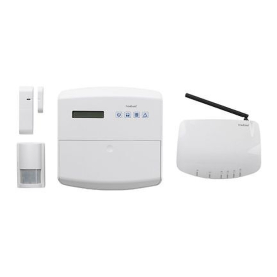
Please visit www.GlobalGuard.Friedland.co.uk to view an online installation video. Further KIT CONTENTS details on setup and operation can be found in The Alarm System should contain the following devices both this and the online software manual 1 x Solar Siren 1 x LCD Control Panel 1 x IP Gateway 1 x Wireless USB Dongle... -
Page 8: Introduction And Overview
left un-occupied, the ‘Fully Arm’ mode will arm INTRODUCTION AND all zones to protect the entire property, (i.e. OVERVIEW upper and lower floors and outbuildings). MULTIPLE USERS The system allows for up to 8 Users, a Master (Admin) and 7 Users to be configured. This allows the system Event Log to maintain a record of which users have armed and disarmed the system. -
Page 9: Zones
typically installed at entry/exit points of your – ‘24-hour Intruder’ mode provides 24 hour property. intruder protection for areas where continuous monitoring is required, (e.g. gun lockers). The system Exit-Delay may be configured for between 10 to 250 seconds or disabled –... -
Page 10: Chime
This enables the user to see which user has The jamming detection circuit will constantly Armed/Disarmed the system and if and when scan for jamming signals. However, it will also any alarms occurred. The time, date and details detect and could in extreme cases be triggered of the event type will be recorded for each by radio signals from other radio equipment system event. -
Page 11: Planning And Extending Your Alarm System
This hardware manual will only detail how to link these devices to the Control Panel. To operate these devices with a Programme, Schedule or Event, please refer to the online software manual available at www.GlobalGuard.Friedland.co.uk. PLANNING AND EXTENDING YOUR ALARM SYSTEM Before attempting to install your Alarm System it is important to study your security requirements and plan your installation accordingly. - Page 12 Typical Installation using only the iii) in the hall covering the Control Panel and routes between downstairs rooms. detectors supplied: 1. Place the 1st Door/Window Detector The system may be expanded with additional (configured on zone 1) on the front door. detectors, Remote Controls and Keypads to 2.
- Page 13 b. Any detectors covering the remainder of the lower floor apart from the entry/exit points (zones1&2) should be left with an instant delay (default for all other zones) for maximum security. c. Any detectors placed upstairs (which are not required when activating Part-Arm-I mode) should not be setup with Part-Arm I ON.
-
Page 14: External Solar Siren
Shadows cast by neighboring walls, trees and EXTERNAL SOLAR SIREN roof overhangs should also be avoided. If the Siren is to be mounted below the eaves, it The Siren is encapsulated within a tough should be positioned a distance of at least twice polycarbonate housing that also provides full the width of the eaves overhang below the protection against adverse weather conditions. -
Page 15: Charging The Solar Siren Battery
Under the cover you will also find a row of 5 DIP CHARGING THE SOLAR SIREN Switches labeled SW3 and a “LEARN” button. BATTERY 1. Ensure that DIP Switch5 of SW3 on the LED Before getting your system up and running, it is indicator board is set to OFF (“SIREN”) for important to initially charge up the battery for the use with this alarm system. -
Page 16: Control Panel
The Control Panel must be located CONTROL PANEL within reach of a mains socket. Note that to fully install the Control Panel in DO NOT fix the Control Panel onto or position, the siren’s battery charging very close to metalwork (i.e. radiators, process must be complete. -
Page 17: Installing The Control Panel
The function keys I/II/III are home automation keys used to operate Programmes setup in the PC setup software INSTALLING THE CONTROL PANEL 4. Ensure that the Reset jumper link (P1) and External Tamper Switch Jumper (P51) are 1. Pull the clip outwards together with pushing set in the OFF position the mounting bracket downwards to detach it from the rear of the Control Panel. -
Page 18: Ip Gateway
IMPORTANT: The keys must be pressed firmly so, again it is advisable to wear ear and within 5 seconds. If you make a mistake, defenders as the tamper alarm will sound. press the “ESC” button and start the sequence again. ... -
Page 19: Installing The Ip Gateway
The internet connection must be free from LINKING AN IP GATEWAY TO THE any firewalls/restrictions that might prevent CONTROL PANEL (OPTIONAL) remote access. The gateway supplied in this kit has been supplied pre-linked to the Control Panel at INSTALLING THE IP GATEWAY the factory therefore you do not need to repeat this. -
Page 20: Deleting The Ip Gateway From The Control Panel(Optional)
PASSIVE INFRA-RED (PIR) MOVEMENT DETECTOR PIR Movement Detectors detect movement in a protected area by detecting changes in infra-red Link push button radiation levels caused for example when a person moves within or across the PIR’s detection pattern. If movement is detected an DELETING THE IP GATEWAY FROM THE alarm will be triggered, (if the system is armed).