YASKAWA S-II Series Instructions Manual
Ac servo drives devicenet application module
Hide thumbs
Also See for S-II Series:
- User manual (447 pages) ,
- User manual (617 pages) ,
- Instructions manual (31 pages)
Table of Contents
Advertisement
Quick Links
サーボドライブ
AC
Σ-II
シリーズ
取扱説明書
アプリケーションモジュール
DeviceNet
形式
JUSP-NS300, JUSP-NS300-E
製品を安全にお使い頂くために,本書を必ずお読みください。
また,本書をお手元に保管していただくとともに,最終的に本製品をご使用になる
ユーザー様のお手元に確実に届けられるよう,お取り計らい願います。
AC Servo Drives
Σ
II
Series
-
INSTRUCTIONS
DeviceNet Application Module
Type JUSP-NS300, JUSP-NS300-E
To properly use the product, read this manual thoroughly and retain
for easy reference, inspection, and maintenance. Ensure the end user
receives this manual.
MANUAL NO. TOB-C718-6C
Advertisement
Table of Contents

Related Manuals for YASKAWA S-II Series


Summary of Contents for YASKAWA S-II Series
- Page 1 サーボドライブ Σ-II シリーズ 取扱説明書 アプリケーションモジュール DeviceNet 形式 JUSP-NS300, JUSP-NS300-E 製品を安全にお使い頂くために,本書を必ずお読みください。 また,本書をお手元に保管していただくとともに,最終的に本製品をご使用になる ユーザー様のお手元に確実に届けられるよう,お取り計らい願います。 AC Servo Drives Σ Series INSTRUCTIONS DeviceNet Application Module Type JUSP-NS300, JUSP-NS300-E To properly use the product, read this manual thoroughly and retain for easy reference, inspection, and maintenance. Ensure the end user receives this manual.
- Page 2 Yaskawa. No patent liability is assumed with respect to the use of the information contained herein. Moreover, because Yaskawa is constantly striving to improve its high-quality products, the information contained in this manual is subject to change without notice.
- Page 3 INTRODUCTION ■ Manual Contents This manual consists of Japanese Version and English Version. • Japanese Version: Described on pages J-1 to J-31. • English Version: Described on pages E-1 to E-30. Use the Japanese Version or English Version as needed. ■...
-
Page 4: Table Of Contents
INSTRUCTIONS Σ - II SERIES SGDH DeviceNet APPLICATION MODULE SYMBOLS FOR SAFE OPERATION - - - - - - - - - - - - - - - - - - - - - - - E-4 NOTES FOR SAFE OPERATION - - - - - - - - - - - - - - - - - - - - - - - - - E-4 1 PARTS - - - - - - - - - - - - - - - - - - - - - - - - - - - - - - - - - - - - - E-8 2 CHECKING ON DELIVERY - - - - - - - - - - - - - - - - - - - - - - - E-9 2.1 Checking Items - - - - - - - - - - - - - - - - - - - - - - - - - - - - - - - - E-9... - Page 5 6 OPERATION - - - - - - - - - - - - - - - - - - - - - - - - - - - - - - - - - E-25 6.1 Precautions at Test Run - - - - - - - - - - - - - - - - - - - - - - - - - E-25 6.2 Precautions at Operation - - - - - - - - - - - - - - - - - - - - - - - - E-26 7 INSPECTION AND MAINTENANCE - - - - - - - - - - - - - - - - E-27 8 MEASURES TO SATISFY THE EMC DIRECTIVE - - - - - - E-28...
- Page 6 This instruction manual covers Σ-II Series SGDH DeviceNet* Application Module (herein- after called NS300 Module), which is an application module to be connected to Σ-II series SGDH SERVOPACK for DeviceNet. To properly use the NS300 Module, read this manual thoroughly and retain for easy refer- ence for inspections and maintenance etc.
-
Page 7: Symbols For Safe Operation
SYMBOLS FOR SAFE OPERATION In this manual, the NOTES FOR SAFE OPERATION are classified as “WARNING” or “CAUTION”. The following symbols are used. Indicates a potentially hazardous situation which, if not avoided, could result in death or WARNING serious personal injury. Indicates a potentially hazardous situation which, if not avoided, may result in minor or CAUTION moderate personal injury and/or damage to the equipment. - Page 8 INSTALLATION CAUTION (Ref.No.) E-13 • Never use the equipment where it may be exposed to splashes of water, corrosive or flammable gases, or near flammable materials. Failure to observe this caution may lead to electric shock or fire. WIRING WARNING (Ref.No.) E-16 •...
- Page 9 YASKAWA representative listed on the last page stating the manual No. on the front cover. • YASKAWA is not responsible for accidents or damages due to any modification of the product made by the user since that will void our guarantee.
- Page 10 WARNING LABEL Disconnect all power and wait 5 min. WARNING before servicing. May causeelectric shock. Do not touch heat sink when power is ON. CAUTION May causeburn. Use proper grounding techniques. SERVOPACK warning label position SERVOPACK Warning Label and Grounding Mark Position...
-
Page 11: Parts
1 PARTS The NS300 Module parts names are as follows: Ground wire: Connected to the terminal marked "G" on the SGDH SERVOPACK. Rotary switches (×1, ×10): Used to set the DeviceNet node address. Rotary switches (DR): Used to set baud rate for DeviceNet. RS-232C Communications Connector (CN11): Used to communicate with the NSxxx Setup Tool. -
Page 12: Checking On Delivery
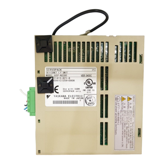
If any of the above items are faulty or incorrect, contact the dealer from which you pur- chased the products or your nearest local sales representative. 2.2 Appearance and Nameplate Application module type Application module name SERVOPACK DeviceNet I/F UNIT MODEL JUSP-NS300 VER. 000000 V81003-69 YASKAWA ELECTRIC MADE JAPAN Serial number Version number NS300 Module... -
Page 13: Type Designation
M4×8 round head screws Use the screw of the front panel. ventilated SGDH-60 to 1EDE-P (with spring washer and plain washer) 1. Remove the connector cover mounted on CN10 of SERVOPACK. SERVOPACK CN10 YASKAWA SERVOPACK SGDH- Connector cover MODE/SET DATA/ CHARGE POWER... - Page 14 2 CHECKING ON DELIVERY 2. Mount an NS300 Module. Connector CN10 (to SERVOPACK) YASKAWA SERVOPACK SGDH Ver. CHARGE POWER 3. For grounding, connect a ground wire of the application module to the marked “G” on the SERVOPACK. Ground wire YASKAWA SERVOPACK...
- Page 15 The appearance of SERVOPACK with application module properly mounted is shown below. E-12...
-
Page 16: Installation
3 INSTALLATION 3 INSTALLATION Σ-II Series SGDH SERVOPACK is a base-mount type servo controller. Incorrect installation will cause problems. Always observe the installation instructions described below. CAUTION • Never use the equipment where it may be exposed to splashes of water, corrosive or flamma- ble gases, or near flammable materials. -
Page 17: Orientation
3.3 Orientation Install the SERVOPACK perpendicular to the wall as shown in the figure below. The SERVOPACK must be orientated as shown in the figure. Firmly secure the SERVOPACK through two to four mounting holes depending on the SER- VOPACK capacity. MADE IN JAPAN Mounting face Ventilation... - Page 18 3 INSTALLATION Where mounted side by side When installing SERVOPACKs side by side, provide at least 10mm (0.4in.) space between them and at least 50mm (2in.) space above and below them as shown in the figure above. Install cooling fans above the SERVOPACKs to prevent the temperature around each SER- VOPACK from increasing excessively and also to maintain the temperature inside the con- trol panel evenly.
-
Page 19: Wiring
4 WIRING This section shows a standard example for connecting Σ-II series products to peripheral devices and briefly explains how to connect each peripheral device. WARNING • SERVOPACK grounding must be in accordance with the national code and consistent with sound local practices. -
Page 20: Devicenet Connection Example
4 WIRING 4.1 DeviceNet Connection Example An example of DeviceNet connection is shown below. DeviceNet Master Module PLC or personal computer PS-03 MP920 CPU-01 260IF OFF ON 63 nodes max. OMRON SERVOPACK SERVOPACK Inverter Machine I/O signals (Manufactured by OMRON or equivalent) 4.2 DeviceNet Communications Connection Example The following diagram shows an example of connections between a host controller and a NS300 Module (CN6) using DeviceNet communications cables. - Page 21 Configuration Elements The network is configured from the following elements. Nodes A node is either a slave that connects to an NS300 Module or similar Module, or the Master that manages the I/O of the slaves. There are no restrictions on the location of the Master or slaves.
- Page 22 4 WIRING Branching to Three Drop Lines Trunk line Trunk line T-Branch Adapter Drop line NS300 NS300 NS300 Module Module Module Direct Node Connection Trunk line Trunk line NS300 Module Multi-drop method Branching from Drop Lines There are three methods that can be used to branch from drop lines. Single Branching Drop line Drop line...
-
Page 23: Devicenet Communications Connectors (Cn6
4.3 DeviceNet Communications Connectors (CN6) The terminal layout and specifications of the CN6 connectors are shown below. Connector Specifications The following table shows the connector specifications. These connectors are metal plated with a flange attached. Name Model Manufacturer Connector MSTB2.5/5–STF–5.08AU PHOENIX CONTACT Case Connector Pin Arrangement... - Page 24 4 WIRING Special DeviceNet cables can be either thick cables or thin cables. The characteristics of each type are given in the following table. Item Cable Type Thick Cable Thin Cable Signal decay Slight Considerable Communications Long distance Short distance distance Characteristics Rigid (difficult to bend)
- Page 25 Total Drop Line Length The total drop line length is a total of all drop line lengths. Length Limits The total drop line length must be within the allowable range and even then, each drop line must be 6 m or less. The allowable range of total drop line length varies with the baud rate as shown in the fol- lowing table.
- Page 26 4 WIRING Basic Precautions Basic precautions are as follows: • The communications power supply to the network must be 24 VDC. • The communications power supply must have a sufficient margin in the capacity. • Connect the communications power supply to the trunk line. •...
-
Page 27: Grounding
4.5 Grounding As shown below, connect the shield wire of the cable to the FG terminal of the communica- tions power supply and ground the shield wire to a resistance of 100Ω or less. Power Supply with Single-point Ground T-Branch Adapter or Power Supply Tap CAN H Communication Shield... -
Page 28: Eds File
JUSP-NS300 NS300.eds JUSP-NS300-E NS300E.eds Download the EDS File from the ODVA’s homepage or Yaskawa’s e-mechatronics site (http://www.e-mechatronics.com/). 6 OPERATION This section provides precautions at test run and operation. For instructions on test run and operation, refer toΣ-II series SGM H/SGDH User’s Manual (SIEPS80000005) and Σ-II series SGDH DeviceNet Application Module User’s Manual (SIE-C718-6). -
Page 29: Precautions At Operation
Check Item during Test Run The following items should be checked during test run. • Unusual vibration • Abnormal noise • Excessive temperature rise 6.2 Precautions at Operation CAUTION • During operation, do not touch the SERVOPACK’s heatsink. Failure to observe this caution may result in burns. E-26... -
Page 30: Inspection And Maintenance
This section describes the basic inspections and maintenance. If any failure occures on SER- VOPACK, refer to Σ-II Series SGM H/SGDH User’s Manual 10.1 Troubleshooting (SIEPS80000005) and Σ-II Series SGDH DeviceNet Application Module User’s Manual (SIE- C718-6). Contact your Yaskawa representative if the problem cannot be solved by the proce- dures described. WARNING •... -
Page 31: Measures To Satisfy The Emc Directive
8 MEASURES TO SATISFY THE EMC DIRECTIVE This section describes the measures required for the NS300 Module to conform to EMC Direc- tive (EN50081-2, EN50082-2). 8.1 DeviceNet Communication Cable For DeviceNet (CN6 connector), use the cable for special use. For max. cable length, refer to “4.4 Precautions for Wiring DeviceNet Cables” Use the special DeviceNet cable. -
Page 32: Cable Clamp
8 MEASURES TO SATISFY THE EMC DIRECTIVE 8.4 Cable Clamp Fix and ground the cable sheld using a piece of conductive metal. <Example of Cable Clamp> SERVOPACK side Ground plate Cable Cable Shield (cable sheath stripped) Fix and ground the cable shield using a piece of conductive metal. -
Page 33: Wiring Examples
8.5 Wiring Examples The following diagrams show the wiring example. Before wiring, turn OFF the power ON/ OFF switch and post a notice of “No Conduction”. Only an electrical expert can perform the wiring. The noise filter and the core are shown in the diagram. <REQUIRED EN SPECIFICATIONS>... - Page 34 Revision History The revision dates and numbers of the revised manuals are given on the bottom of the back cover. MANUAL NO. TOB-C718-6 Published in Japan October 2000 00-7 Date of Revision number publication Date of original publication Date of Rev.
- Page 35 Phone 81-4-2962-5151 Fax 81-4-2962-6138 http://www.yaskawa.co.jp YASKAWA AMERICA, INC. 2121 Norman Drive South, Waukegan, IL 60085, U.S.A. Phone 1-800-YASKAWA (927-5292) or 1-847-887-7000 Fax 1-847-887-7310 http://www.yaskawa.com YASKAWA ELÉTRICO DO BRASIL LTDA. Avenida Piraporinha 777, Diadema, São Paulo, 09950-000, Brasil Phone 55-11-3585-1100 Fax 55-11-3585-1187 http://www.yaskawa.com.br...