Table of Contents
Advertisement
Quick Links
HOME THEATER SYSTEM
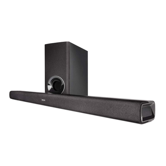
DHT-S316
• For purposes of improvement, specifications and design are subject to change without notice.
• Please use this service manual when referring to the operating instructions without fail.
• Some illustrations used in this service manual are slightly different from the actual product.
Service Manual
Click here!
On-line service parts list
http://dmedia.dmglobal.com/Document/DocumentDetails/25211
ONLINE PARTS LIST
(P5)
WEB owner's manual
NA:
http://manuals.denon.com/DHTS316/NA/EN/index.php
EU:
http://manuals.denon.com/DHTS316/EU/EN/index.php
AP:
http://manuals.denon.com/DHTS316/AP/ZH/index.php
JP:
http://manuals.denon.com/DHTS316/JP/JA/index.php
Upload is planned for the time of a future press release.
BEFORE SERVICING THIS UNIT
ELECTRICAL
MECHANICAL
REPAIR INFORMATION
UPDATING
Please refer to the MODIFICATION NOTICE.
Confidential
Ver. 4
Advertisement
Table of Contents

Related Manuals for Denon DHT-S316


Summary of Contents for Denon DHT-S316
- Page 1 Service Manual Ver. 4 HOME THEATER SYSTEM DHT-S316 Click here! On-line service parts list http://dmedia.dmglobal.com/Document/DocumentDetails/25211 ONLINE PARTS LIST (P5) WEB owner’s manual http://manuals.denon.com/DHTS316/NA/EN/index.php http://manuals.denon.com/DHTS316/EU/EN/index.php http://manuals.denon.com/DHTS316/AP/ZH/index.php http://manuals.denon.com/DHTS316/JP/JA/index.php Upload is planned for the time of a future press release. BEFORE SERVICING THIS UNIT...
- Page 2 BEFORE SERVICING THIS UNIT SAFETY PRECAUTIONS NOTE FOR SCHEMATIC DIAGRAM HANDLING THE SEMICONDUCTOR AND OPTICS ONLINE PARTS LIST Accessing the Parts List Searching Part Numbers or Ref. Numbers NOTE FOR PARTS LIST SERIAL NUMBER Serial Number Organization SKU Code of this Unit...
-
Page 3: Safety Precautions
SAFETY PRECAUTIONS The following items should be checked for continued protection of the customer and the service technician. Leakage current check Before returning the set to the customer, be sure to carry out either (1) a leakage current check or (2) a line to chassis resistance check. If the leakage current exceeds 0.5 milliamps, or if the resistance from chas- sis to either side of the power cord is less than 460 kohms, the set is defective. -
Page 4: Note For Schematic Diagram
NOTE FOR SCHEMATIC DIAGRAM WARNING: Parts indicated by the z mark have critical characteristics. Use ONLY replacement parts recommended by the manufacturer. CAUTION: Before returning the set to the customer, be sure to carry out either (1) a leakage current check or (2) a line to chassis resistance check. - Page 5 ONLINE PARTS LIST Accessing the Parts List Searching Part Numbers or Ref. Numbers (1) Access from the Service Manual You can search a Parts List for part numbers or Ref. numbers. ・ Click the URL link on the cover of the service manual. (1) Enter the part number or Ref.
- Page 6 SERIAL NUMBER Serial Number Organization The 14-digit serial number that contains the code of the manufacturing plant and the manufacturing date. 14 digits Factory Manufactured Cumulative Year, month code code serial number The last Month 2digit of year (01 ~ 12) SKU Code of this Unit Product SKU SKU Code...
-
Page 7: Schematic Diagrams
ELECTRICAL SCHEMATIC DIAGRAMS SCH01 SoundBar 1 MAIN Power Supply SCH02 SoundBar 2 MAIN MTK8301 SCH03 SoundBar 3 MAIN STA339BW SCH04 SoundBar 4 MAIN USB&IR SCH05 SoundBar 5 MAIN HDMI SCH06 SoundBar 6 MAIN IA3S4 SCH07 SoundBar 7 BLUETOOTH SCH08 SoundBar 8 KEY & LED SCH09 SoundBar 9 Power Supply SCH10 SubWoofer 1 SCH11 SubWoofer 2... - Page 8 SCHEMATIC DIAGRAMS SCH01 SoundBar 1 MAIN Power Supply STBY_5V 6PIN/2.5mm 6PIN/2.5mm POWER_15V POWER_15V AMP_VCC C176 C176 0.1uF/50V/X7R 0.1uF/50V/X7R 4.7uH/2A 4.7uH/2A XP21 XP21 FB20 FB20 600/2A 600/2A 56K/1% 56K/1% 390K 390K C238 C238 100uF/25V 100uF/25V 0.1uF/50V/X7R 0.1uF/50V/X7R 10K/1% 10K/1% 100K 100K TPS562200DDCR TPS562200DDCR STBY_5V...
- Page 9 SCH02 SoundBar 2 MAIN MTK8301 A_1V2 A_1V2 C808 C808 C805 C805 SD_3V3 R112 R112 DQ15 C177 C177 10pF/50V/NP0 10pF/50V/NP0 DQ15 VDDQ VSSQ C117 C117 DQ14 C179 C179 10pF/50V/NP0 10pF/50V/NP0 DQ14 DQ13 STB_3V3 DQ13 SD_3V3 100pF/50V/NP0 100pF/50V/NP0 VSSQ VDDQ RGB_SCL DQ12 DQ12 DQ11 DQ11...
- Page 10 SCH03 SoundBar 3 MAIN STA339BW SYS_5V 2.2uH/30mA 2.2uH/30mA CE11 CE11 47uF/6.3V/SMD 47uF/6.3V/SMD STBY_5V 470pF/50V/C0G 470pF/50V/C0G 470pF/50V/C0G 470pF/50V/C0G SYS_3V3 AGND AGND C932 C932 C933 C933 500Ω/800mA 500Ω/800mA PCM1808PWR PCM1808PWR 0.1uF/16V/X7R 0.1uF/16V/X7R MP3_R C802 C802 10uF/10V/X5R 10uF/10V/X5R 10uF/10V/X5R 10uF/10V/X5R R969 R969 R970 R970 4.7K 4.7K...
- Page 11 SCH04 SoundBar 4 MAIN USB&IR AMP_15V AMP_VCC FB16 FB16 300/3A 300/3A FB17 FB17 300/3A 300/3A CE15 CE15 +3.3VD +3.3VD 100uF/25V 100uF/25V C120 C120 NC/4.7K NC/4.7K 4.7K 4.7K 4.7K 4.7K 1000pF/50V/X7R 1000pF/50V/X7R 4.7K 4.7K VDD_DIG GND_SUB TP42 TP42 GND_DIG TP44 TP44 AMP_SCL R163 R163...
- Page 12 SCH05 SoundBar 5 MAIN HDMI TO the page of OPT HDMI_ARC HDMI_ARC TO the page of MTK8301 HPLG HPLG HDMI_SDA HDMI_SDA HDMI_SCL HDMI_SCL STBY_5V HDMI_5V HDMI_CEC TX2+ HDMI_CEC TX2+ R199 R199 HDMI_5V TX2+ TX2- TX2+ TX2- MBRX120/20V/1A MBRX120/20V/1A TX2- R1016 R1016 TX2- D_3V3...
- Page 13 SCH06 SoundBar 6 MAIN IA3S4 3.3V TP45 TP45 TP46 TP46 3.3V C290 0.1uF/16V/X7R C290 0.1uF/16V/X7R R223 R223 WL_BCLK1 R972 R972 ABCLK CON2 CON2 WL_LRCK1 R974 R974 BUSY1 ALRCLK WL_DATA1 R973 R973 RF_3P_2GNDS RF_3P_2GNDS AMP_DATA1 GPIO33 GPIO26 GPIO27 R225 R225 WL_LRCK1 LRCK C291 C291...
- Page 14 SCH07 SoundBar 7 BLUETOOTH CON2 CON2 NC/RF_3P_2GNDS NC/RF_3P_2GNDS 0/NC 0/NC BT_ANT 2.4nH 2.4nH SF CS SF CK From the page of MTK8301 SF DO 0.3pF/50V/HQC 0.3pF/50V/HQC SF CK 0.75pF/50V/HQC 0.75pF/50V/HQC AGND SPI_CLK SF CS BT VDD BT_STATES MICINR SPI_SS BT_CON BT_CON MICINL GPIOB11...
- Page 15 SCH08 SoundBar 8 KEY & LED LED_VDD TAC SWITCH TAC SWITCH LED9 POWER POWER1 POWER INPUT BT_Pairing VOL+ 6.8K/1% 6.8K/1% VOL- INPUT INPUT1 LED8 R_EXT OUT8 LED7 LED_VDD OUT7 TAC SWITCH TAC SWITCH LED6 OUT6 LED5 OUT5 SN3112I320E-09 SN3112I320E-09 BT_Pairing BT_Pairing1 SN3112I320E-09 SN3112I320E-09...
- Page 16 SCH09 SoundBar 9 Power Supply RS1M RS1M RM10 RM10 FUSE_3.15AL/250V FUSE_3.15AL/250V KBP306 KBP306 2.74M 2.74M 2.74M 2.74M 1000pF/630V 1000pF/630V 1000pF/630V 1000pF/630V 150K 150K 2PIN/7.92mm 2PIN/7.92mm 68uF/400V 68uF/400V 2.74M 2.74M 2.74M 2.74M 20mH 20mH 10A/200V 10A/200V RS1M RS1M 200uH min 200uH min 6PIN/2.5mm 6PIN/2.5mm R7 4.7...
- Page 17 SCH10 SubWoofer 1 RS1M RS1M ATQ27 ATQ27 FUSE_3.15AL/250V FUSE_3.15AL/250V KBP306 KBP306 XP10 XP10 19V/1.8A 2.74M 2.74M 2.74M 2.74M 2200pF/630V 2200pF/630V 1000pF/630V 1000pF/630V POWER_18V 150K 150K 2PIN/7.92mm 2PIN/7.92mm 68uF/400V 68uF/400V 2.74M 2.74M 2.74M 2.74M 20mH 20mH 20A/200V 20A/200V CON1_1 CON1_1 CON1_2 CON1_2 RS1M RS1M...
- Page 18 SCH11 SubWoofer 2 NC/4PIN/2.0mm NC/4PIN/2.0mm R1022 R1022 STB_3V3 STB_3V3 R625 R625 2.2K 2.2K LED601 LED601 LED_GREEN LED_GREEN ON/PAIRING STB_3V3 RESET_AMP PAIRING_LED R615 R615 4.7K 4.7K Q606 Q606 Status light NPN_3DG3904M NPN_3DG3904M R624 R624 4.7K 4.7K PAIRING_LED GPIO33 GPIO26 PAIRING_KEY GPIO27 2.4nH 2.4nH SUB_LRCK...
- Page 19 SCH12 SubWoofer 3 +3.3VD1 SYS_3V3 +3.3VD1 +3.3VD2 FB32 FB32 500/200mA 500/200mA C207 C207 AMP_18V +3.3VD1 4.7K 4.7K C621 C621 C620 C620 +3.3VD1 R88 4.7K R88 4.7K 0.1uF/50V/X7R 0.1uF/50V/X7R C226 C226 +3.3VD1 0.1uF/50V/X7R 0.1uF/50V/X7R VDD_DIG GND_SUB R85 4.7K R85 4.7K 1000pF/50V/X7R 1000pF/50V/X7R GND_DIG AMP_SCL...
- Page 20 SCH13 SubWoofer 4 FB615 FB615 500/200mA 500/200mA R118 R118 7.5K/1% 7.5K/1% MP3_L R1021 R1021 MP3_R FB616 FB616 500/200mA 500/200mA 7.5K/1% 7.5K/1% 5PIN/CKX-3.5-29 5PIN/CKX-3.5-29 AGND C958 C958 C959 C959 Audio inPUT 8pin0.5mm 8pin0.5mm XP23 XP23 MP3_L AGND MP3_R AGND SPDIF_OPT 3.3V C971 C971 R778...
- Page 21 PRINTED CIRCUIT BOARDS For SoundBar MAIN, POWER, KEY, AUX OPT Lead-free Solder When soldering, use the Lead-free Solder (Sn-Ag-Cu). MAIN (A SIDE) MAIN (B SIDE) R171 C133 C131 TM36 PBZ1 R130 R987 TM39 R169 XP11 CON2 C117 R966 C142 TM23 C292 R175 C124...
- Page 22 For Subwoofer POWER POWER (A SIDE) POWER (B SIDE) FB33 R487 TM37 TM33 R623 TM36 R620 C227 R621 TM15 TM10 R622 C618 TM23 R488 TM31 LED601 C226 R615 TM22 TM39 R613 C613 TM13 R1022 T=1.6mm FB16 TM12 C621 C530 40-POLKMK-AMD2G C620 R776 C207...
- Page 23 BLOCK DIAGRAM and POWER DIAGRAM for SoundBar System Diagram Block for bar XTAL SDRAM FLASH 27MHZ 64Mb 16Mb 25W*2@4R,THD+N=30% FLASH SPDIF ATS2823 16Mb I2S0 PCM1808 AUDIO IN I2S1 SPDIF OPT IN STA339BW I2C/IO MT8301 HDMI_ARC 74LVC2G04 HDMI HDMI OUT USB upgrade only I2S2 I2C/IO Wireless...
- Page 24 BLOCK DIAGRAM and POWER DIAGRAM for Subwoofer System Diagram Block for subwoofer I2S1 50W /4Ω @THD+N=30% PBTL STA369BW Wireless Module IA3S4 SW601 LED601 DC-DC STB_3.3V SY8213FCC POWER Board power signal other PVDD Standard module New module Un-standard module...
- Page 25 WIRING DIAGRAM for SoundBar WIRING DIAGRAM for SoundBar AUDIO IN FLASH SDRAM PCM1808 16Mb 64Mb 8P FFC AUX OPT PCB 4P Wire 74LVC2G04 STA339BW OPT IN MT8301 HDMI ARC DC-DC MAIN PCB JW5222 Wireless Module DC-DC DC-DC IA3S JW5222 TPS562200 XP21 20P FFC 4P Wire...
- Page 26 WIRING DIAGRAM for Subwoofer WIRING DIAGRAM for Subwoofer DC-DC SMPS SY8213FCC AC JACK Wireless STA369BW Module Subwoofer IA3S Pair button Pair LED POWER(AM)PCB...
- Page 27 Remote Code Table Maker Code(Co C1) Byte 1 Byte 2 DENON (3254H) 00101010 01001100 Key No. Name Genre 1(D0) Genre 1(D1) DATA Code 1(D2) Parity(Dp) Byte 3 Byte 4 Byte 5 Byte 6 ① KEY SYSTEM (5H) AMP/RECIEVER(2H) AUX(088H) 0 0 0 0 1 0 1 0 0 1 0 0 0 0 0 1...
- Page 28 MECHANICAL DISASSEMBLY Flowchart 1. BAFFLE ASSY 2. PCB 3. SPEAKERS 4. POWER PCB for SubWoofer EXPLODED VIEW for SoundBar EXPLODED VIEW for SubWoofer SEALING GASKET VIEW OF AN AIR LEAK PREVENTION for SoundBar PACKAGING VIEW...
- Page 29 DISASSEMBLY Flowchart • Remove each part following the flow below. • Reassemble the removed parts in the reverse order. • Read "SAFETY PRECAUTIONS" before reassembling the removed parts. • If wire bundles are removed or moved during adjustment or part replacement, reshape the wires after completing the work. Failure to shape the wires correctly may cause problems such as noise. • See "EXPLODED VIEW for SoundBar" • See "EXPLODED VIEW for SubWoofer" SoundBar SubWoofer BAFFLE ASSY POWER PCB for SubWoofer DISASSEMBLY DISASSEMBLY 1. BAFFLE ASSY 4. POWER PCB for SubWoofer and "EXPLODED VIEW" and "EXPLODED VIEW" Ref. No. of EXPLODED VIEW : C 1 Ref. No. of EXPLODED VIEW : C 31 Ref. No. of EXPLODED VIEW : C 2 Ref. No. of EXPLODED VIEW : C 39 Ref. No. of EXPLODED VIEW : C 6 Ref. No. of EXPLODED VIEW : C 29 Ref. No. of EXPLODED VIEW : C 7 Ref. No. of EXPLODED VIEW : C 28 Ref. No. of EXPLODED VIEW : C 9 Ref. No. of EXPLODED VIEW : C 30 SPEAKERS DISASSEMBLY DISASSEMBLY 2. PCB 3. SPEAKERS and "EXPLODED VIEW"...
- Page 30 1. BAFFLE ASSY • For the shooting direction of each photos used in this manual, see the photo below. • A, B, C and D in the photo below indicate the shooting directions of photos. Proceeding : BAFFLE ASSY • The photographs with no shooting direction indicated were taken from the top of the unit. (1) Remove the screws. • Photos of DHT-S316 E3 are used in this manual. View from the Rear ↑Top Side↑ The viewpoint of each photograph for SoundBar (Shooting direction : X) [View from the top] ↓Bottom Side↓ ↓Shooting direction: B↓...
- Page 31 2. PCB 4. POWER PCB for SubWoofer Proceeding : BAFFLE ASSY → Proceeding : POWER PCB for SubWoofer (1) Remove the screws. (1) R emove the screws. Remove the connector. View from the Rear REAR HOUSING BAFFLE ASSY (2) Remove the connector. Peel off Glue and disconnect the antenna wire. REAR HOUSING PCB MAIN PCB POWER BAFFLE ASSY XP11 glue...
- Page 32 EXPLODED VIEW for SoundBar http://dmedia.dmglobal.com/Document/DocumentDetails/25211 Parts List : BAFFLE ASS’Y : 1, 2, 3, 4, 19, 21 WARNING: Parts marked with this symbol z have critical characteristics. Use ONLY replacement parts recommended by the manufacturer.
- Page 33 EXPLODED VIEW for SubWoofer http://dmedia.dmglobal.com/Document/DocumentDetails/25211 Parts List : CABINET ASS’Y WITH SPEAKER : 1, 2, 3, 4, 5, 6, 7, 8, 9, 10, 16, 17 WARNING: Parts marked with this symbol z have critical characteristics. Use ONLY replacement parts recommended by the manufacturer.
- Page 34 SEALING GASKET VIEW OF AN AIR LEAK PREVENTION for SoundBar ↓Bottom Side↓ BAFFLE ASSY ↑Top Side↑ ↓Top Side↓ REAR HOUSING ↑Bottom Side↑ REF No. Part No. Part Name Remarks Q'ty EVA L910 X W15 X T0.5MM 54-306940-000 EVA L420 X W15 X T0.5MM 54-306950-000 3,5,9,11,15 919471101310S EVA L1000 X W8 X T0.5MM X 15PCS / SHEET CUT_3 EVA L40~49 X W8 X T0.5MM Cut 919471101310S before use. L=40~49MM CUT_5 EVA L90~100 X W8 X T0.5MM Cut 919471101310S before use. L=90~100MM CUT_9 EVA L10~12 X W8 X T0.5MM Cut 919471101310S before use.
- Page 35 PACKAGING VIEW http://dmedia.dmglobal.com/Document/DocumentDetails/25211 Parts List : UK plug (UK Only) Part A Part B...
-
Page 36: Repair Information
REPAIR INFORMATION TROUBLE SHOOTING 1. The unit does not power on (SoundBar) 2. Keys do not work (SoundBar) 3. BT cannot work (SoundBar) 4. AUX IN cannot work 5. HDMI ARC cannot work 6. OPTICAL cannot work 7. SUBWOOFER cannot work 8. -
Page 37: Keys Do Not Work
TROUBLE SHOOTING 1. The unit does not power on 3. BT cannot work (SoundBar) (SoundBar) Check the cable and connection. Check the power supply voltage. KEY PCB to MAIN PCB Replace the FFC. Replace the [U1]. MAIN PCB [BT VDD, BT_VCC] [U4-U18 : 20pin FFC] Check the voltage. - Page 38 5. HDMI ARC cannot work 7. SUBWOOFER cannot work Check the voltage. Check the LED Check the power supply. MAIN PCB Replace [U17 or U6]. LED601 POWER_18V [U17: SYS_3V3, U6: STB_3V3] Lit? Replace the MAIN PCB Reconnect the SUBWOOFER Check the voltage. POWER PCB Replace the [M1].
-
Page 39: Special Mode Setting Button
SPECIAL MODE Special mode setting button b No. 1 : While the power is on, hold down buttons "A", "B", and "C" for at least 4 seconds . b No. 2 : While the power is on, hold down buttons "A", "B", and "C" for at least 5 seconds . Mode Button A Button B... -
Page 40: Version Display Mode
1. Version Display Mode 3. Demo Mode 1.1. Actions (1) Demo Modes are ways to configure the sound bar with specific settings which are more desirable or Version information is displayed when the device is started in this mode. even required for certain commercial retail point of sale installations. (2) You cannot go from one demo mode to another. -
Page 41: Input Indication
BLUETOOTH ○ (Blue) [Source]+[VOL +], Press & Hold 9 sec ○ (Red) ○ (Red) *: DHT-S316 Only Blinking 3 times on 0.5 sec Entry Demo mode (Retail Display Mode) OUTPUT indication [Source]+[VOL +], Press & Hold 12 sec ○ (Red) ○... - Page 42 UPDATING PROCEDURE AFTER REPLACING THE U-COM, ETC. FIRMWARE UPDATE PROCEDURE 1. Items necessary for update 2. How to Update...
- Page 43 PROCEDURE AFTER REPLACING THE U-COM, ETC. The procedure after replacing the u-COM (microprocessor), flash ROM, etc. is as follows. Procedure PCB Name Ref. No. Description Remark after Re- placement MAIN IA3S4 (BAR) WIRELESS MODULE : Tx POWER IA3S4 (SUB) WIRELESS MODULE : Rx Procedure after Replacement A : The software has been written.
-
Page 44: Firmware Update Procedure
1. Items necessary for update Items necessary for update are as follows. Offered / not Offered Update Type Needed Part for Update Requirement Standard Service Equipment Purchase from D&M Article code Download from SDI Not offered by D&M Update DHT-S316.BIN... -
Page 45: How To Update
(2) The firmware update finishes. Copy the downloaded file to the USB root directory. Press the power button to turn off the power. File name DHT-S316.BIN (3) After updating the firmware, check the version. "1. Version Display Mode" ---Cautions on Firmware Update--- •... - Page 46 Copyright © 2018-2019 D&M Holdings Inc. All Rights Reserved.