Table of Contents
Advertisement
Quick Links
INSTALLATION
INSTRUCTIONS
HP29-090
HP29-120
HEAT PUMPS
504,342M
11/2000
See unit nameplate for manufacturer and address.
©2000
Shipping & Packing List
1 - Assembled heat pump unit
Check the unit for shipping damage. If you find any dam
age, immediately contact the last carrier.
General Information
These instructions are intended as a general guide and do
not supersede national or local codes in any way. Consult
authorities having jurisdiction installation.
IMPORTANT
Improper installation, adjustment, alteration, service
or maintenance can cause property damage, person
al injury or loss of life. Installation and service must
be performed by a qualified installer or service
agency.
11/00
*2P1100*
(7.5 TON)
(10 TON)
Litho U.S.A.
RETAIN THESE INSTRUCTIONS FOR FUTURE REFERENCE
HP29-090
Table of Contents
. . . . . . . . . . . . . . . . . . . . . . . . . . . . . . . . . . . .
. . . . . . . . . . . . . . . . . . . . . . . . . . . . . . . . . . .
. . . . . . . . . . . . . . . . . . . . . . . . . . . . . .
. . . . . . . . . . . . . . . . . . . . . . . . . . . . . . . .
. . . . . . . . . . . . . . . . . . . . . . . . . . . . . . . . . . . .
. . . . . . . . . . . . . . . . . . . . . . . . . . . . . . . . . . .
. . . . . . . . . . . . . . . . . . . . . . . . . . . . . . . .
The Clean Air Act of 1990 bans the intentional vent
ing of refrigerant (CFC's and HCFC's) as of July 1,
1992. Approved methods of recovery, recycling or
reclaiming must be followed. Fines and/or incarcera
tion may be levied for noncompliance.
As with any mechanical equipment, personal injury
can result from contact with sharp sheet metal
edges. Be careful when you handle this equipment.
HP29-120
Page 1
. . . . . . . . . . . . . . . . . . . . . . .
. . . . . . . . . . . . . . . . . . . . . . . . . .
. . . . . . . . . . . . . . . . . . . . . . . . . . . . .
. . . . . . . . . . . . . . . . . . . . . . . . . . .
. . . . . . . . . . . . . . . . . . . . . . . . . . . . . .
. . . . . . . . . . . . . . . . . . . . .
. . . . . . . . . . . . . . . . . . . .
. . . . . . . . . . . . . . . . . . . . . . . . . . .
IMPORTANT
CAUTION
504,342M
*P504342M*
1
1
2
3
6
7
7
10
15
16
17
17
18
19
21
Advertisement
Table of Contents

Related Manuals for Lennox HP29-090


Summary of Contents for Lennox HP29-090
-
Page 1: Table Of Contents
Setting the Unit ......HP29-090 Rigging the Unit for Lifting ..... -
Page 2: Unit Dimensions
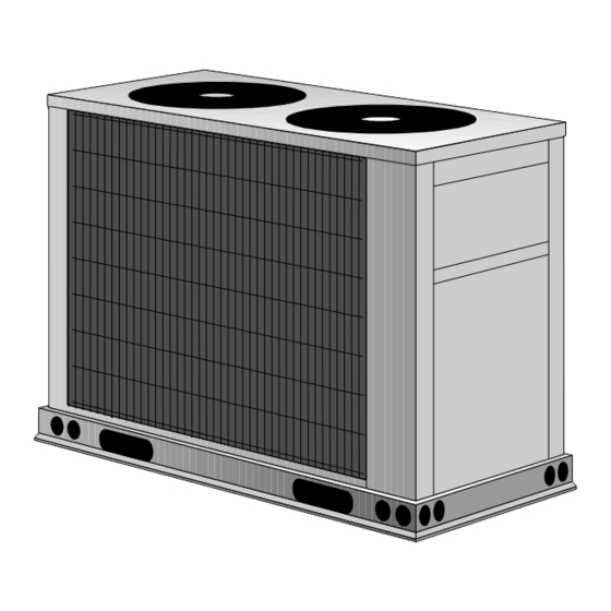
HP29-090 Series Dimensions - inches (mm) CORNER WEIGHT CENTER OF GRAVITY Model No Model No. Model No Model No. lbs. lbs. lbs. lbs. inch inch HP29-090 HP29-090 22-1/2 OUTDOOR FAN AND GUARD INLET COMPRESSOR INLET CENTER OF GRAVITY OUTDOOR COIL... - Page 3 HP29-120 Series Dimensions - inches (mm) CORNER WEIGHT CENTER OF GRAVITY Model No Model No. Model No Model No. lbs. lbs. lbs. lbs. inch inch HP29-120 HP29-120 17-3/4 OUTDOOR COIL CONTROL OUTDOOR COIL INLET AIR CENTER OF GRAVITY OUTDOOR FANS AND GUARDS (2) OPTIONAL HAIL GUARD OPTIONAL HAIL GUARD...
-
Page 4: Parts Arrangement
HP29-090 Unit Parts Arrangement FAN GUARD OUTDOOR FAN CONTROL BOX (B4) REVERSING VALVE DEFROST THERMOSTAT (S6) COMPRESSOR (B1) DEFROST PRESSURE HIGH PRESSURE SWITCH SWITCH (S46) (S4) VAPOR LINE SERVICE VALVE LOW AMBIENT SWITCH LOSS OF CHARGE SWITCH (S24) (S11) LIQUID LINE... - Page 5 HP29-090 Control Box Arrangement TRANSFER RELAY COMPRESSOR LOW AMBIENT CONTACTOR BY-PASS RELAY OUTDOOR FAN RELAY K10 DISCONNECT DEFROST SWITCH RELAY K4 CMCI GROUND DEFROST/TIMER RELAY SWITCH CAPACITOR C1 TERMINAL STRIP TB14 FIGURE 3 HP29-120 Control Box Arrangement RELAY SWITCH TERMINAL...
-
Page 6: Setting The Unit
(914) available from address shown below, or contact your supervisor. OUTDOOR COIL (914)* Lennox Industries Inc. P.O. Box 799900 (914)* Dallas, TX 75379-9900 HP29-120 Setting the Unit Refer to unit dimensions on page 1 for sizing mounting (914)* slab, platforms or supports. -
Page 7: Rigging The Unit For Lifting
Rigging the Unit for Lifting WARNING Rig unit for lifting by attaching four cables to holes in unit Unit must be grounded in accordance with base rail. See figure 6. national and local codes. 1 - Detach wooden base protection before rigging. Electric Shock Hazard. - Page 8 TYPICAL UNIT WIRING DIAGRAM HP29-090 *2P1100* *P533542W* FIGURE 8 Page 8...
- Page 9 TYPICAL UNIT WIRING DIAGRAM HP29-120 *2P1100* *P533543W* FIGURE 9 Page 9...
-
Page 10: Plumbing
LIQUID LINE VAPOR LINE control to allow for cooling down to 0°F (-18°C). Due to the additional refrigerant required to fill the lines, HP29-090 5/8 in. (16 mm) 1-3/8 in. (35 mm) the likelihood of slugging is greatly increased with lines HP29-120 5/8 in. - Page 11 HCFC 22 LIQUID LINE PRESSURE DROP/VELOCITY At 45°F Evaporating Temperature and 125°F Condensing Temperature HCFC 22 LIQUID LINE PRESSURE DROP (lbs./100 Feet) 10 9 8 7 1.0 .9 .8 .7 .6 12.5 EXAMPLE: 10 TON UNIT 5/8 IN. O.D. LINE 4.25 PSI DROP PER 100 FEET 275 FPM VELOCITY...
- Page 12 125°F UNIT SIZE: 5/8in. COPPER (280psi per table 2). Lennox equipment is designed to hold TWO 90° LONG RADIUS ELBOWS @ 5/8in. O.D. = 1 ft. EQUIV. FT. EA. a charge allowing 10°F subcooling at 95°F ambient. The...
- Page 13 The resultant pressure drop must be (refer to figure 14). Capacity ratings given in the Lennox considered. Page 13...
- Page 14 HCFC 22 VAPOR LINE PRESSURE DROP/VELOCITY PER 100 FT. OF LINE At 45°F Evaporating Temperature and 125°F Condensing Temperature HCFC 22 VAPOR LINE PRESSURE DROP (lbs./100 Feet) 10 9 8 7 1.0 .9 .8 .7 .6 12.5 12.5 EXAMPLE: 10 TON UNIT 1 3/8 IN.
-
Page 15: Service Valves
1.5 psi. This loss has already been included in the capacity is supplied to protect the Schrader valve from contamina given in Lennox' Engineering Handbook, so it should be sub tion and serve as the primary leak seal. tracted from the total. -
Page 16: Leak Testing
To Access Schrader Port: 2 - Using a service wrench, turn the stem counterclock wise for 1/4 of a turn. 1 - Remove service port cap with an adjustable wrench. 3 - Replace the stem cap and tighten it firmly. 2 - Connect gauge to the service port. -
Page 17: Evacuation & Dehydration
Evacuation & Dehydration CAUTION IMPORTANT Danger of Equipment Damage. Avoid deep vacuum operation. Do not use compres Units are shipped with a holding charge of dry air and sors to evacuate a system. helium which must be removed before the unit is Extremely low vacuums can cause internal arcing evacuated and charged with refrigerant. -
Page 18: Charging
Discharge Vapor Discharge Vapor Temperature + 10 psig + 5 psig + 10 psig + 5 psig 65°F (18°C) 75°F (24°C) 85°F (29°C) 95°F (35°C) 105°F (41°C) 115°F (46°C) * HP29-090 tested with CB17/CBH17-95V. **HP29-120 tested with CB17/CBH17-135V. Page 18... -
Page 19: System Operation
Ambient Temp. °F (°C) closes and signals the defrost control that a defrost cycle is needed. If the defrost thermostat is still closed after the HP29-090 9.2 + 1 (5.0 + .5) field-selected compressor run time (30, 60 or 90 minutes) HP29-120 11.3 + 1 (6.0 + .5) -
Page 20: Maintenance
3 - Visually inspect connecting lines and coils for evidence DEFROST CONTROL BOARD of oil leaks. 4 - Check wiring for loose connections. 5 - Check for correct voltage at the unit while the unit is op erating and while it is off. 6 - Check amp-draw of the outdoor fan motor.