Siemens SIMATIC ET 200S Manual
Distributed i/o
Hide thumbs
Also See for SIMATIC ET 200S:
- Manual (652 pages) ,
- Operating instructions manual (418 pages) ,
- Installation and operating manual (216 pages)
Table of Contents
Advertisement
Quick Links
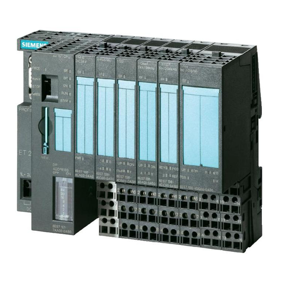
SIMATIC ET 200S distributed I/O Power module PM-E DC24..48V (6ES7138-4CA50-0AB0)
SIMATIC
ET 200S distributed I/O
Power module PM-E DC24..48V
(6ES7138-4CA50-0AB0)
Manual
04/2007
A5E01119980-01
Preface
______________
Properties
______________
Parameters
______________
Diagnostics
______________
Configuring
1
2
3
4
Advertisement
Table of Contents

Related Manuals for Siemens SIMATIC ET 200S


Summary of Contents for Siemens SIMATIC ET 200S
- Page 1 Preface SIMATIC ET 200S distributed I/O Power module PM-E DC24..48V (6ES7138-4CA50-0AB0) ______________ Properties ______________ Parameters SIMATIC ______________ Diagnostics ET 200S distributed I/O Power module PM-E DC24..48V ______________ Configuring (6ES7138-4CA50-0AB0) Manual 04/2007 A5E01119980-01...
- Page 2 Trademarks All names identified by ® are registered trademarks of the Siemens AG. The remaining trademarks in this publication may be trademarks whose use by third parties for their own purposes could violate the rights of the owner.
-
Page 3: Preface
Additional support If you have any questions relating to the products described in these operating instructions, and do not find the answers in this document, please contact your local Siemens representative. http://www.siemens.com/automation/partner... - Page 4 Please contact your regional training center or the central training center in D -90327, Nuremberg, Germany. Phone: +49 (911) 895-3200. http://www.siemens.com/sitrain Technical Support You can reach technical support for all A&D projects ● using the support request web form: http://www.siemens.com/automation/support-request...
-
Page 5: Table Of Contents
Table of contents Preface ..............................3 Properties ..............................7 Power module PM-E DC24..48V (6ES7138-4CA50-0AB0)............7 Parameters .............................. 11 Diagnostics .............................. 13 Diagnostics using LED display.....................13 Error types............................14 Configuring .............................. 15 Configuring the address space ....................15 Index................................ 17 Power module PM-E DC24..48V (6ES7138-4CA50-0AB0) Manual, 04/2007, A5E01119980-01... - Page 6 Table of contents Power module PM-E DC24..48V (6ES7138-4CA50-0AB0) Manual, 04/2007, A5E01119980-01...
-
Page 7: Properties
Properties Power module PM-E DC24..48V (6ES7138-4CA50-0AB0) Properties ● The power module PM-E DC24..48V monitors the supply voltage for all the electronic modules in the voltage group. The supply voltage is fed in by means of the TM-P terminal module. ● You can use all the electronic modules except the 2DI AC120V ST, 2DI AC230V ST, and 2DO AC24..230V/1A in the voltage group of the PM-E DC24..48V power module. - Page 8 Properties 1.1 Power module PM-E DC24..48V (6ES7138-4CA50-0AB0) Address space of inputs/outputs Address space of inputs/outputs by selecting the following as an option: Options Address space of the inputs Address space of the outputs Status byte (S) 1 byte Option handling (O) 8 bytes 8 bytes Status byte and option handling...
- Page 9 Properties 1.1 Power module PM-E DC24..48V (6ES7138-4CA50-0AB0) Block diagram Figure 1-1 Block diagram of the PM-E DC24..48V power module Technical data PM-E DC24..48V (6ES7138-4CA50-0AB0) Dimensions and weight Dimension B (mm) Weight Approx. 35 g Voltages, currents, potentials Rated load voltage 24 VDC to 48 VDC Reverse polarity protection •...
- Page 10 Properties 1.1 Power module PM-E DC24..48V (6ES7138-4CA50-0AB0) Power module PM-E DC24..48V (6ES7138-4CA50-0AB0) Manual, 04/2007, A5E01119980-01...
-
Page 11: Parameters
Parameters Parameters The following table lists the power module parameters. Table 2-1 Parameters for power modules PM-E 24 to 48 VDC Range of values Default setting Applicability Diagnostics: No load voltage disable/enable Disable Power module The parameters are explained below. Diagnostics: No load voltage Use this parameter to enable a diagnostic message because there is no load voltage. - Page 12 Parameters Power module PM-E DC24..48V (6ES7138-4CA50-0AB0) Manual, 04/2007, A5E01119980-01...
-
Page 13: Diagnostics
Diagnostics Diagnostics using LED display Power module LED displays on the power module: ① Batch error (red) ② Load voltage (green) Status and error displays by means of LEDs on power modules The table below shows the status and error displays on the power module. Event (LEDs) Cause Remedy... -
Page 14: Error Types
Diagnostics 3.2 Error types Error types Power module error types The diagnostic message is reported on channel 0 and applies to the entire module. The table below shows the types of errors affecting power modules Table 3-1 Power module error types Error type Meaning Remedy... -
Page 15: Configuring
Configuring Configuring the address space Address area for option handling and status byte You can control and monitor option handling, and evaluate the status byte of the power module using the control (PIO) and feedback interface (PII). The address range of the control (PIO) and feedback interface (PII) depends on how the corresponding entry in the configuration software is configured, or which entry has been selected. - Page 16 Configuring 4.1 Configuring the address space Status byte for power modules Figure 4-1 Assignment of status byte for power modules Power module PM-E DC24..48V (6ES7138-4CA50-0AB0) Manual, 04/2007, A5E01119980-01...
-
Page 17: Index
Index Basic knowledge requirements, 3 Parameters Block diagram, 9 for power modules, 11 Power modules, 13 Error types, 14 Parameters, 11 Properties, 7 Disposal, 3 Recycling, 3 Internet Service & Support, 4 Scope Manual, 3 Maximum configuration, 7 Service & Support, 4 Technical data, 9 Technical Support, 4 Terminal assignment, 8... - Page 18 Index Power module PM-E DC24..48V (6ES7138-4CA50-0AB0) Manual, 04/2007, A5E01119980-01...