
Related Manuals for Planar RPS


Summary of Contents for Planar RPS
- Page 1 User Guide RPS and Video Controller RS232 Planar RPS and Video Controller RS232 User Guide Page | 1 020-1332-00I...
- Page 2 Planar employees. When you purchase a Planar product, you get more than a display, you get the service and support you need to maximize your investment. To find the latest warranty and service information regarding your Planar product, please visit http://www.planar.com/support/...
-
Page 3: Table Of Contents
Using the RPS USB Connection ........ -
Page 4: Rs232 Communication
Serial Commands via USB" on page 37 and "Sending Serial Commands Via TCP or UDP" on page 46 for details on those physical connections. Applicable Models This RS-232 user manual applies to all Planar RPS and Video Controller models. RS232 user manuals for other products can be found at www.planar.com/support/. RS232 Setup The RS232 connection must use the following settings: •... -
Page 5: Connecting The Rs232 Cable
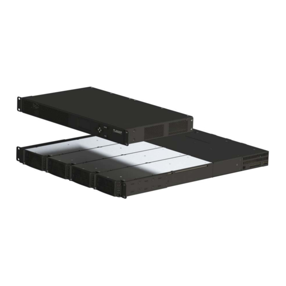
Connecting the RS232 Cable Connecting the RS232 Cable The RS232 cable will connect to a PC or control system, depending on your setup. Remote Power Supply Models Video Controller Models Planar RPS and Video Controller RS232 User Guide Page | 5 020-1332-00I... -
Page 6: Rj45 And Db9 Standard Rs232 Pinout
Connecting the RS232 Cable RJ45 and DB9 Standard RS232 Pinout Pin RJ45 Jack Signal Description Receive Transmit 4, 5 Ground 1, 2, 7, 8 No Connect Planar RPS and Video Controller RS232 User Guide Page | 6 020-1332-00I... -
Page 7: Rs232 Protocol
This may be due to disconnected equipment or a poor communication path. • [No operator] denotes an action. In this case, there’s no operator and no operand. Planar RPS and Video Controller RS232 User Guide Page | 7 020-1332-00I... -
Page 8: Protocol Encoding
• Modifiers and operands can be separated by commas, spaces or both (e.g. “PANEL.ACTIVE=0 0 1280 720”, “PANEL.ACTIVE=0,0,1280,720” and “PANEL.ACTIVE=0, 0, 1280, 720” are all the same). Responses will always separate with one space between modifiers and operands). Planar RPS and Video Controller RS232 User Guide Page | 8 020-1332-00I... -
Page 9: Examples
Example of an invalid operand (the Brightness command doesn’t accept a string operand) model.id = 1 [CR] MODEL.ID!ERR 6 [CR] Example of an invalid operator (cannot write to this command) Planar RPS and Video Controller RS232 User Guide Page | 9 020-1332-00I... -
Page 10: Rs232 Codes
• ‘!’ in the Operators column indicates that the command accepts the execute operator, which uses no operator symbol. The ‘!’ symbol is not included in the command. Planar RPS and Video Controller RS232 User Guide Page | 10 020-1332-00I... -
Page 11: Advanced
Then enter the following command Operand #1: Unsigned Integer\ continuously until it returns NAK: DISABLE 0\ HELP(NEXT)? ENABLE 1\ OFF 0\ ON 1\ NO 0\ YES 1\ FALSE 0\ TRUE 1\ Planar RPS and Video Controller RS232 User Guide Page | 11 020-1332-00I... - Page 12 Loop Signal 1=IN1 LOOP.ROUTE(VC2)=IN3 Gets / sets the input that will be routed to Output 2=IN2 LOOP.ROUTE(VC2):IN3 the loop out on the specified video 3=IN3 controller. 4=IN4 5=DP Planar RPS and Video Controller RS232 User Guide Page | 12 020-1332-00I...
- Page 13 RESET.PANEL(3):@ACK factory state. VC.AUTO.ENABLE. Auto Enable VC 0=DISABLE=OFF=NO= VC.AUTO.ENABLE.ADDRESS=0 Gets / sets the auto enabling of VC ADDRESS FALSE VC.AUTO.ENABLE.ADDRESS:OFF addressing to on or off. 1=ENABLE=ON=YES= TRUE Updated Planar RPS and Video Controller RS232 User Guide Page | 13 020-1332-00I...
-
Page 14: Basic Control
Toggles system power between on and off. No FALSE SYSTEM.POWER:ON 1=ENABLE=ON=YES= TRUE SYSTEM.REBOOT System Reboot 2402 SYSTEM.REBOOT Reboots the system and all system SYSTEM.REBOOT:@ACK powered connected components. Updated Planar RPS and Video Controller RS232 User Guide Page | 14 020-1332-00I... -
Page 15: Color Balance
Panel ID 0.0 - 100.0 WHITE.BALANCE(1 RED)? Gets / sets the white balance value for the Setting ….and…. WHITE.BALANCE(1 RED):100.000000 given LCD and color channel 0=RED 1=GREEN 2=BLUE 255=ALL Planar RPS and Video Controller RS232 User Guide Page | 15 020-1332-00I... -
Page 16: Configuration
PSW# String DEVICE.NAME(PSW4)="LEFT COLUMN" Gets / sets for specified device the unique Name DEVICE.NAME(PSW4):"LEFT COLUMN" name associated. Quotes must be used to set any names that have spaces. Planar RPS and Video Controller RS232 User Guide Page | 16 020-1332-00I... - Page 17 3 times rapidly and cycle this behavior several times. INPUT. Input Brightness VC#.IN# 0-100 INPUT.BRIGHTNESS(VC1.IN4)=56 Gets / sets the input brightness value for BRIGHTNESS INPUT.BRIGHTNESS(VC1.IN4):56 the specified input. Planar RPS and Video Controller RS232 User Guide Page | 17 020-1332-00I...
- Page 18 1230 MASTER 0=DISABLE=OFF=NO= IPV4.ENABLE=1 Toggles the equipment to use dynamic STATIC FALSE IPV4.ENABLE:1 host configuration protocol. Modifier 1=ENABLE=ON=YES= MASTER and STATIC are equivalent. For TRUE DHCP, see NETWORK.DHCP. Planar RPS and Video Controller RS232 User Guide Page | 18 020-1332-00I...
- Page 19 MODEL.NAME Component 2306 String MODEL.NAME? Returns the directly connected equipment Model MODEL.NAME:"RPS220-3" model name without modifier. Returns the MODEL.NAME(PN3)? specified equipment’s model name with 10.0 PSW# MODEL.NAME(PN3):"MX55U" modifier. Planar RPS and Video Controller RS232 User Guide Page | 19 020-1332-00I...
- Page 20 1=ENABLE=ON=YES= TRUE OSD.MARGIN OSD Offset 1313 =?+- 0-400 OSD.MARGIN=10 Gets / sets the OSD position in pixels away OSD.MARGIN:10 from edges set by OSD.POSITION. No effect on OSD.POSITION=CENTER. Planar RPS and Video Controller RS232 User Guide Page | 20 020-1332-00I...
- Page 21 Set Panel ID 1524 1-65535 1-65535 PANEL.ID(5)=3 Sets an existing panel ID to a new panel ID. PANEL.ID(5):3 If there are duplicate IDs, the first found will be changed. Planar RPS and Video Controller RS232 User Guide Page | 21 020-1332-00I...
- Page 22 Gets / sets the test pattern displayed for all 1=BLACK PATTERN:GREEN displays connected to the system. 2=WHITE 3=RED 4=GREEN 5=BLUE 6=CYAN 7=MAGENTA 8=YELLOW 9=GRAY 10=CUSTOM_COLOR 11=RED_SCALE 12=GREEN_SCALE 13=BLUE_SCALE 14=GRAY_SCALE 15=LOGO 16=GRID 18=CONTRAST 20=COLOR_BARS Planar RPS and Video Controller RS232 User Guide Page | 22 020-1332-00I...
- Page 23 Gets / sets the baud rate for the connected 19200 SERIAL.DEVICE:19200 component. Default is 19200. Note: Data 38400 bits, parity and stop bits are always 8, N, 1. 57600 115200 Planar RPS and Video Controller RS232 User Guide Page | 23 020-1332-00I...
- Page 24 IP addresses on the static 1=ENABLE=ON=YES= network. TRUE VC.COUNT Number of Video 1604 Integer VC.COUNT? Returns the number of video controllers Controllers VC.COUNT:4 configured in the system. Planar RPS and Video Controller RS232 User Guide Page | 24 020-1332-00I...
- Page 25 Wall Pixel Height Integer WALL.HEIGHT=3840 Gets / sets the wall height pixels. WALL.HEIGHT:3840 WALL.WIDTH Wall Pixel Width Integer WALL.WIDTH=2160 Gets / sets the wall width pixels. WALL.WIDTH:2160 Updated Planar RPS and Video Controller RS232 User Guide Page | 25 020-1332-00I...
-
Page 26: Time Zone Setting-Operands
91=UTCP1000.CANBERRA.MELBOURNE.SYDNEY 39=UTCP0100.BRUSSELS.COPENHAGEN.MADRID.PARIS 92=UTCP1000.GUAM.PORT.MORESBY 40=UTCP0100.SARAJEVO.SKOPJE.WARSAW.ZAGREB 93=UTCP1000.HOBART 41=UTCP0100.WEST.CENTRAL.AFRICA 94=UTCP1000.MAGADAN 42=UTCP0100.WINDHOEK 95=UTCP1000.VLADIVOSTOK.MAGADAN.RTZ.9 43=UTCP0200.AMMAN 96=UTCP1100.CHOKURDAKH.RTZ.10 44=UTCP0200.ATHENS.BUCHAREST 97=UTCP1100.SOLOMON.IS.NEW.CALEDONIA 45=UTCP0200.BEIRUT 98=UTCP1200.ANADYR.PETROPAVLOVSK.KAMCHATSKY.RTZ.11 46=UTCP0200.CAIRO 99=UTCP1200.AUCKLAND.WELLINGTON 47=UTCP0200.DAMASCUS 100=UTCP1200.COORDINATED.UNIVERSAL.TIMEP12 48=UTCP0200.HARARE.PRETORIA 101=UTCP1200.FIJI 49=UTCP0200.HELSINKI.KYIV.RIGA.SOFIA.TALLINN.VILNIUS 102=UTCP1300.NUKU.ALOFA 50=UTCP0200.ISTANBUL 103=UTCP1300.SAMOA 51=UTCP0200.JERUSALEM 104=UTCP1400.KIRITIMATI.ISLAND 52=UTCP0200.KALININGRAD.RTZ.1 Planar RPS and Video Controller RS232 User Guide Page | 26 020-1332-00I... -
Page 27: Monitoring Setup
2409 0=ALL RESET.ALERTS(WEB) Resets alert settings to the factory default 1=WEB RESET.ALERTS(WEB):@ACK for the specified UI. If no modifier is 2=EMAIL provided, it is treated as all. 3=SNMP Planar RPS and Video Controller RS232 User Guide Page | 27 020-1332-00I... -
Page 28: Presets
Returns if a preset slot value is in use. See PRESET.STATUS AND PRESET.LIST. PRESET.STATUS Preset Status 2009 Integer 1-999 0=EMPTY PRESET.STATUS(1)? Returns whether a specified preset slot 1=FULL PRESET.STATUS(1):FULL currently has information stored. Updated Planar RPS and Video Controller RS232 User Guide Page | 28 020-1332-00I... -
Page 29: Security
Set User 2410 String String PASSWORD.SET=123 Sets the password for the 'admin' account Password PASSWORD.SET="123" in the WallDirector software. Command many not be set via port 57 service. Planar RPS and Video Controller RS232 User Guide Page | 29 020-1332-00I... -
Page 30: Status
Returns the specified VC fan status. 1=FAULT FAN.STATUS:OK FUSE.OPEN Auxiliary RPS 1434 0=NO FUSE.OPEN(PS1)? Returns the fuse status for each fuse on the Fuse Status 1=YES FUSE.OPEN:YES YES specified device. Planar RPS and Video Controller RS232 User Guide Page | 30 020-1332-00I... - Page 31 PANEL.RX.LENGTH(PN3):"<20m" the VC to the specified panel. PANEL.SIGNAL. Output Cable 1536 String PANEL.SIGNAL.QUALITY(PN2)? Returns panel signal quality as a string. QUALITY Signal Quality PANEL.SIGNAL.QUALITY(PN2):"-22dB, - 22dB, -23dB, -22dB" Planar RPS and Video Controller RS232 User Guide Page | 31 020-1332-00I...
- Page 32 12 = Unspecified Fault 13 = VAC fault warning 14 = IDC fault or warning 15 = VDC fault or warning 0xFFFFFFFF = Module not present, invalid or off Planar RPS and Video Controller RS232 User Guide Page | 32 020-1332-00I...
- Page 33 Returns the voltage for the specified power VOLTAGE(PS1.MODULE1):118.203354 supply module. TIME.STRING System Time 1103 String TIME.STRING? Returns system current date and time in a TIME.STRING:"2018-12-14 22:59:30" standard format. Updated Planar RPS and Video Controller RS232 User Guide Page | 33 020-1332-00I...
-
Page 34: Zone Setup And Control
Creates duplicate zone with ID of operand ZONE.DUPLICATE(4):8 based on the zone ID in the modifier. ZONE.DUPLICATE(7)=0 Operand of zero will create zone with the ZONE.DUPLICATE(7):8 next numerically unassigned zone ID. Planar RPS and Video Controller RS232 User Guide Page | 34 020-1332-00I... - Page 35 Maximize Zone 2604 Integer ZONE.MAXIMIZE(3) Sets a zone to display an image over the ZONE.MAXIMIZE:@ACK entire active area controlled by the system. Only applicable to the active display/preset. Planar RPS and Video Controller RS232 User Guide Page | 35 020-1332-00I...
- Page 36 Only applicable to the active display/preset. ZONE.SOURCE Zone Input 2608 Integer String ZONE.SOURCE(1)? Gets / sets the input routed to a zone. Only ZONE.SOURCE(1):"HDMI VC2.IN2" applicable to the active display/preset. Planar RPS and Video Controller RS232 User Guide Page | 36 020-1332-00I...
-
Page 37: Sending Serial Commands Via Usb
USB drivers. You can skip this section if you have already installed the USB drivers on your computer. USB drivers may be obtained from the Planar Partner Portal website at https://partners.planar.com/ Automatically installing the USB drivers In most cases, the USB driver installation can be performed using the automated driver installation program included on the USB flash drive in your accessory kit. - Page 38 Sending Serial Commands via USB When the Planar USB Driver Installer page opens, click “Next”. The USB drivers will be automatically installed. Planar RPS and Video Controller RS232 User Guide Page | 38 020-1332-00I...
- Page 39 Windows will detect the new hardware and attempt to install the drivers on its own. If you do not see the “Installing device driver software” message, then the driver installation previously failed. Skip to step 5. Planar RPS and Video Controller RS232 User Guide Page | 39 020-1332-00I...
- Page 40 If driver installation succeeds, you will see a message like the one shown below. If so, driver installation is complete. If Windows’ attempt at installing the drivers fails, you will need to manually install the drivers using the steps below. Planar RPS and Video Controller RS232 User Guide Page | 40 020-1332-00I...
- Page 41 Open the Start menu and select “Control Panel”. Select “Device Manager”. In the Device Manager, there will be a “Planar Display” item in the “Other Devices” section. Right-click on Planar Display and select “Update Driver Software”. Planar RPS and Video Controller RS232 User Guide...
- Page 42 Make sure the “Include subfolders” checkbox is checked. The USB drivers are included on the USB flash drive in the accessory kit; they can also be obtained from http://www.planar.com/support. Use the “Browse” button to locate the directory where the USB drivers are located. Click “Next”.
- Page 43 Beginning with the release of Windows 10 v.1607, all drivers must be digitally signed by the Windows Hardware Developer Center Dashboard (WHDCD) portal. Planar is currently in process of having this driver signed by the WHDCD. If there are issues stating that no compatible driver is found when trying to recognize the device, a manual installation will be required.
-
Page 44: Using The Rps Usb Connection
The USB-B connection will appear in the COM port list of each serial terminal program. Any terminal program such as Tera Term can be used to test the connection. Planar RPS and Video Controller RS232 User Guide Page | 44 020-1332-00I... - Page 45 Select the Port Settings tab from the window that opened and from the pull down menu under Bits per second select 19200. Click OK and exit out of the Device Manager. Planar RPS and Video Controller RS232 User Guide Page | 45 020-1332-00I...
-
Page 46: Sending Serial Commands Via Tcp Or Udp
Video Controller Models Note: Windows 10 has a command line based telnet capability that is not installed by default. To install, follow the instructions below: Open Control Panel. Planar RPS and Video Controller RS232 User Guide Page | 46 020-1332-00I... - Page 47 Sending Serial Commands Via TCP or UDP Open Programs and Features. Select the Turn Windows features on or off option. Select the Telnet Client check box. Planar RPS and Video Controller RS232 User Guide Page | 47 020-1332-00I...
- Page 48 Click OK. A box will appear that says “Windows feature” and “Searching for required files.” When complete, the Telnet client should be installed. 6. Open the program by searching from the Start menu. Planar RPS and Video Controller RS232 User Guide Page | 48 020-1332-00I...
- Page 49 • Port 57 is selected • Service is set to “Other” to indicate that TCP is being used without Telnet or SSH Planar RPS and Video Controller RS232 User Guide Page | 49 020-1332-00I...
- Page 50 Note: Most UDP terminal programs won’t automatically send the [CR] at the end of the command, so the hex command (0d 0a) is used to do this manually. Planar RPS and Video Controller RS232 User Guide Page | 50 020-1332-00I...
- Page 51 INPUT.OFFSET, 18 CUSTOM.COLOR, 16 INPUT.PRESENT, 31 INPUT.RESET, 18 IPV4.ADDRESS, 18 IPV4.ENABLE, 18 DEVICE.DELETE, 16 IPV4.GATEWAY, 19 DEVICE.GROUP, 16 IPV4.NETMASK, 19 DEVICE.NAME, 16 IR.CODE, 19 DEVICE.REBOOT, 11 IR.LOCK, 19 Planar RPS and Video Controller RS232 User Guide Page | 51 020-1332-00I...
- Page 52 QCONFIG, 14 OSD.MARGIN, 20 OSD.POSITION, 21 OSD.TIMEOUT, 21 OUTPUT.COLOR.DEPTH, 21 OUTPUT.MODE, 21 RESET, 23 OUTPUT.VREFRESH, 21 RESET.ALERTS, 27 RESET.BALANCE, 15 RESET.CANCEL, 23 RESET.LAYOUT, 23 RESET.PANEL, 13 PANEL.ACTIVE, 21 Planar RPS and Video Controller RS232 User Guide Page | 52 020-1332-00I...
- Page 53 TIME.STRING, 33 TIMEZONE, 24 TIMEZONE.STRING, 24 UPTIME, 33 VC.AUTO.ADDRESS.ENABLE, 24 VC.AUTO.ENABLE.ADDRESS, 13 VC.COUNT, 24 VC.LIST, 25 VC.START.ADDRESS, 25 VOLTAGE, 33 WALL.BRIGHTNESS, 25 WALL.HEIGHT, 25 WALL.RGB.GAIN, 15 WALL.WIDTH, 25 Planar RPS and Video Controller RS232 User Guide Page | 53 020-1332-00I...