Advertisement
Quick Links
Advertisement

Related Manuals for GE DINAMAP PRO Series


Summary of Contents for GE DINAMAP PRO Series
- Page 1 ® DINAMAP Series 100-400V2 Monitor Operation Manual...
- Page 2 ® DINAMAP PRO 400V2 Monitor...
- Page 3 4502 Woodland Corporate Boulevard Tampa, FL 33614 1-877-274-8456 Part No. 2009802-001B The content of this document including all figures and drawings is proprietary information of GE Medical Systems Information Technologies, provided solely for purposes of operation, maintenance or repair, and dissemination for...
- Page 4 Such problems include device malfunction, device failure, damage to the device or damage to other property. A caution relates to steps in a procedure. © GE Medical Systems Information Technologies, 2002. All rights reserved. Tampa, FL 33614 Printed in the U.S.A.
- Page 5 Contents Introduction ................7 ® About the DINAMAP PRO Monitor ..............7 Product Compliance ....................10 Symbols ........................11 Getting Started..............13 Unpacking the Monitor and Accessories ............13 Power Sources ......................13 Powering the Monitor .....................13 Rear Panel Connections ..................16 Front Panel Controls and Indicators ..............17 Switching the Monitor On and Off...............19 Liquid Crystal Display (LCD)...................19 Using the Printer .......................20...
- Page 6 Appendix A................77 Technical Specifications...................77 BP ..........................77 Temperature.......................78 ..........................78 Mechanical .........................82 Power Requirements....................82 Environmental ......................83 Appendix B ................85 Patient Alarms......................85 System Alarms ......................85 Failsafe Alarm......................85 Hierarchy of Alarms....................86 Appendix C................91 Principles of Noninvasive Blood Pressure Determination........91 Appendix D ................95 Reorder Codes......................95 Appendix E ................97 Warranty, Service, and Spare Parts ...............97 Repairs.........................98...
- Page 7 Introduction ® About the DINAMAP PRO Monitor ® DINAMAP PRO Monitors provide noninvasive determination of systolic blood pressure, diastolic blood pressure, mean arterial pressure, pulse rate, temperature, and oxygen saturation. These portable AC- and DC-operated monitors are primarily intended for use in hospital acute care settings such as outpatient surgery, accident and emergency, labor and delivery, GI/endoscopy, and medical/surgical units.
- Page 8 • If powering the Monitor from an external power adapter or converter, use only power adapters and converters approved by GE Medical Systems Information Technologies. • The Monitor does not include any user-replaceable fuses. Refer servicing to qualified service personnel.
- Page 9 • Place the PRO Monitor on a rigid, secure surface. Monitor must only be used with mounting hardware, poles, and stands recommended by GE Medical Systems Information Technologies. See Appendix D. • The weight of the accessory basket contents should not exceed 6.6 lb (3 kg).
- Page 10 Product Compliance ® The DINAMAP PRO Monitor is classified in the following categories for compliance with IEC 601-1: • Class l, internally powered • Transportable • For continuous operation • Not suitable for use in the presence of flammable anesthetics •...
- Page 11 Symbols The following symbols are associated with the PRO Monitor. Note: The type of model determines which symbols appear on the Monitor. Attention, consult accompanying documents Defibrillator-proof type BF equipment Power ON/OFF START/STOP BP AUTO BP Battery Power MAP (Mean Arterial Pressure) mmHg Temperature Beats Per Minute...
- Page 12 Packaging label depicting the transportation and storage atmospheric pressure range of 500 to 1060 hPa. ® The DINAMAP PRO Monitor is protected against vertically falling drops of water and conforms to IEC-529 standard at level of IPX1 IPX1. Vertically falling drops of water shall have no harmful effects to the Monitor.
- Page 13 This is also a good time to check for any damage or shortage. If there is a problem or shortage, contact GE Medical Systems Information Technologies. It is recommended that all the packaging be retained, in case the Monitor must be returned for service in the future.
- Page 14 charging. If the battery is not inserted, the external power indicator LED will flash (short flash approx. every 4 sec). When the Monitor is running on battery power, a battery icon appears in LCD area 3 (toggling with the time indicator) indicating the charge status.
- Page 15 Getting Started in a medical/hospital grade attachment plug, provided with the following cord tag: “Hospital Grade Plug." Grounding integrity can only be maintained when equipment is connected to an equivalent receptacle marked "Hospital Grade." • Where the integrity of the external earth conductor in the installation or its arrangement is in doubt, the Monitor must be operated from its internal battery.
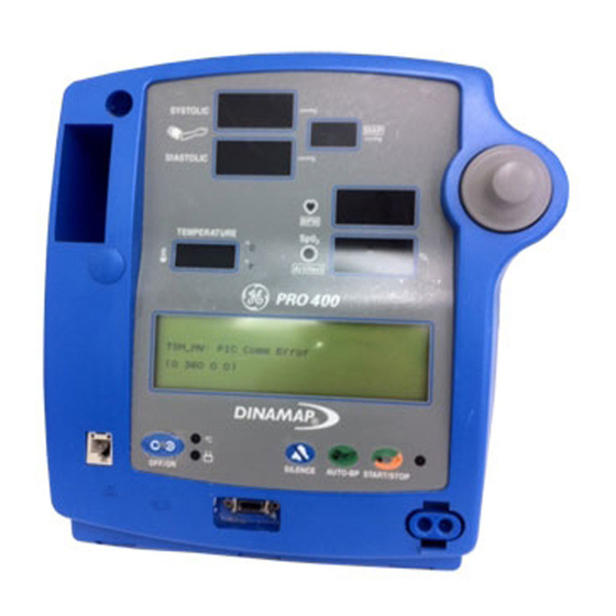
- Page 16 1 Battery compartment cover: Retains and protects internal battery. 2 Mains input: Used to connect to AC power supply. 3 External power socket: To be used with approved GE Medical Systems Information Technologies AC-DC power converter ONLY. 4 Inactive temperature cable storage: Inactive temperature probe cable attaches here (Models 200V2 and 400V2).
- Page 17 Getting Started Front Panel Controls and Indicators 7 Systolic pressure display: 3-digit red LED indicates measured systolic BP in mmHg. 8 Active temperature probe holster: Temperature probe that is being used stored here (Models 200V2 and 400V2). 9 Diastolic pressure display: 3-digit red LED indicates measured diastolic BP in mmHg.
- Page 18 14 External power indicator: Green LED indicates external power status and battery charging status of monitor. 15 Temperature probe connector: Temperature probe cable attaches here (Models 200V2 and 400V2). 16 ON/OFF switch: Controls on/off state of monitor; push for power on and push again for power off. 17 Battery power indicator: Yellow LED indicates operation and charge status of internal battery.
- Page 19 Getting Started Switching the Monitor On and Off To switch the DINAMAP PRO Monitor on, press and hold the power ON/OFF switch (16) for at least 10 seconds or press the rotor (21). As the Monitor powers up, it will run a short self-test routine, which will flash all the indicator lights and then beep the warning speaker.
- Page 20 appears dark on a light background, while the text of selected buttons appears light on a dark background. Note: Some menus have six option buttons. In these cases, there is no space available to display the menu title. Area 2 This area displays data from one of three different sources.