
Related Manuals for GE B20


Summary of Contents for GE B20
- Page 1 B40/B20 Patient Monitor User's Guide English 2081499-002 E (Paper) 21 November 2014 © 2014 General Electric Company. All rights reserved.
- Page 3 Related to software VSP-C 0459 All specifications are subject to change without notice. Document no. 2081499-002 E 21 November 2014 GE Medical Systems Information Technologies, Inc. GE Healthcare 8200 West Tower Avenue 3F Building 1, GE Technology Park Milwaukee, WI USA...
-
Page 4: Table Of Contents
Contents About this manual ......1 Impedance respiration ......79 About this device . -
Page 5: About This Manual
This manual contains instructions necessary to operate this device in accordance with its functions and intended use. Descriptions refer In this manual, the B40 Patient Monitor and B20 Patient Monitor are to the software VSP-C referred to as “the monitor” when a function or a feature applies to Information which refers only to certain versions of the product is both. - Page 6 CIC Pro Clinical Information Center Operator's Manual • CARESCAPE Central Station User’s Manual Ordering manuals A paper copy of this manual will be provided upon request. Contact your local GE representative and request the part number on the first page of the manual.
-
Page 7: About This Device
About this device Indications for use: B40 Indications for use: B20 This device is a portable multi-parameter unit to be used for This device is a portable multi-parameter unit to be used for monitoring and recording of, and to generate alarms for, multiple... - Page 8 GE Medical Systems Information Technologies, Inc. is responsible for If the product malfunctions or if assistance, service, or spare parts the safety, reliability and performance of the equipment only if: are required, contact GE service for technical support or contact − Assembly operations, extensions, readjustments, modifications, your local representative.
- Page 9 Classifications CE marking information In accordance with IEC 60601-1: CE compliance − Class I and internally powered equipment - the type of protection The monitor bears CE Mark CE-0459 indicating its conformity with against electric shock. the provisions of the Council Directive 93/42/EEC concerning −...
- Page 10 Product Compliance Exception • This equipment is suitable for connection to public mains as defined in CISPR 11. The ECG parameter conforms to IEC 60601-2-27, with exception of • This Monitor conforms to general safety standard for medical Sub-clause 201.12.1.101.15 QRS detection. devices to IEC 60601-1.
-
Page 11: Safety Precautions
Safety precautions These safety messages refer to the entire system. The message specific to parts of the system can be found in the relevant section. a malfunction as a result of the product being physically Safety message signal words damaged due to cleaning, disinfection, re-sterilization and/or Safety message signal words designate the severity of a potential reuse. - Page 12 contact with line voltage by inserting metal objects, such as the Caution safety messages pins of leadwires, into the sockets of the power cord by mistake. The following caution safety messages apply to this monitoring • If liquid has accidentally entered the system or its parts, system.
-
Page 13: System Introduction
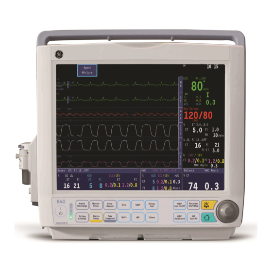
System introduction Safety precautions System components NOTE: Your system may not include all these components. Consult Warnings your local representative for the available components. • All system devices must be connected to the same power supply circuit • EXCESSIVE LEAKAGE CURRENT - Do not use a multiple socket outlet or extension cord. - Page 14 Frame front view B40 Front view B20 Front view 1. Transportation handle 2. Alarm light 3. Trim knob 4. Command board keys 5. Battery compartment 6. Guide rail for GCX mounting 7. Mains power and battery LEDs 8. On/Off key 9.
- Page 15 Frame back view Input/Output adapter and connectors B40 back view B20 back view 1. Receptacle for power cord 2. Serial port 3. Defibrillator connector 4. Nurse call connector 5. Network connector 6. Equipotential connector 7. Multi I/O connector NOTE: 2,3,4 is on the multiple Input/Output adapter.
- Page 16 Acquisition modules E-miniC module B40 acquisition modules: • E-miniC • E-sCO, E-sCAiO • N-CAiO • E-Entropy B20 acquisition modules: • E-miniC • E-Entropy 1. Water trap 2. Sample gas inlet 3. Gas outlet...
- Page 17 E-sCO, E-sCAiO module N-CAiO module E-sCAiO E-sCO 1. D-fend Pro water trap 2. Gas sampling line connector (sampling gas in) 1. D-fend Pro water trap 3. Water trap container 2. Gas sampling line connector (sampling gas in) 4. Gas exhaust line connector (sampling gas out) 3.
- Page 18 E-Entropy module 1. Module keys 2. Entropy connector...
- Page 19 The user can identify Hemo connectors’ configuration from connectors and label. Basic feature Optional feature Hemo connectors’ type Identifier NIBP Temperature Hemo with GE SpO GE SpO SpO2_IBP_T Hemo with Masimo SpO Masimo SpO MasimoSpO2_IBP_T Hemo with Nellcor SpO Nellcor SpO...
- Page 20 Command board keys Admit/ Monitor Print/ Airway Alarm NIBP Auto NIBP Discharge Setup Record Zero All On/Off Reset Take Pt.Data & Alarms Recorder SpO2 NIBP Start/ Others Trends Setup Snapshot Cancel Start/Stop (10) Audio pause active alarms (1) ON/OFF key (11) Return to normal screen view (2a) Battery status LED (light-emitting diode), see "Battery indicators"...
-
Page 21: Symbols
Symbols Type BF (IEC 60601-1) protection against electric − On the rear panel: shock. Isolated (floating) applied part suitable for − Electric shock hazard. Do not open the front intentional external and internal application to the or back cover. Servicing of the product patient, excluding direct cardiac application. - Page 22 On the screen: Gas outlet. Audio alarms paused indicator - Indicates all audio alarms are paused and the amount of time remaining for the alarm pause period displays as a Degree of ingress protection. countdown timer. Displays in the upper left corner Degree of protection against harmful ingress of of the screen.
- Page 23 Underwriters Laboratories product certification Atmospheric pressure limitations. mark. Medical Equipment with respect to electrical shock, fire and mechanical hazards only in accordance with ANSI/AAMI ES60601-1:2005/ 3ZG9 (R)2012 and A1:2012, C1:2009/(R)2012 and A2:2010/ Recycled materials or may be recycled. (R)2012; CSA CAN/CSA-C22.2 NO. 60601-1:14; IEC 60601-2-26;...
- Page 24 Respiration indicator. Indicates a breath is detected by the impedence respiration algorithm. This symbol indicates that the waste of electrical and electronic equipment must not be disposed as unsorted municipal waste and must be collected separately. Please, contact an authorized representative of the manufacturer for information concerning the decommissioning of your equipment.
-
Page 25: Monitoring Basics
Monitoring basics Warnings Inserting and removing acquisition modules • Ensure modules are oriented with release latch downward to To use the acquisition module, your monitoring device need to be ensure retention. pre-configured with the extension rack. • The parameter modules are not able to withstand unpacked drops from a height of 1 m without damaging the module latches. - Page 26 Main screen layout Using menus A menu is a list of functions or commands. To display a menu, press The main screen displays alarms, trends, waveforms, digits, and the one of the keypad keys. main menu in pre-defined areas. Trim Knob To select menu options with control: Trim Knob...
- Page 27 • Admit/discharge status On the CARESCAPE network, the monitor is able to: • Patient demographic information • communicate with GE CARESCAPE CIC pro version 4.0.8, 4.1.1 • Alarm settings and 5.1.0 • communicate with GE CARESCAPE Central Station v1 •...
- Page 28 Additionally, on the CARESCAPE network, the monitor supports Connection to Network remote parameter and waveform configurations from the central Ensure that the appropriate network infrastructure is in place prior station. to the installation of the patient monitor. NOTES: • The Entropy parameter is not supported by CIC pro and NOTE: The network installation and configuration are performed by CARESCAPE Central station.
- Page 29 LEDs indicate the current charging level and any result in injury/burns to the patients or users. Only use batteries Monitor possible failures. You can check the battery status through recommended or manufactured by GE. Setup - Battery Setup. For additional information please refer to the •...
- Page 30 Battery indicators Checking the battery charge when the monitor is turned Screen Explanation Front panel battery LEDs Monitor is battery Orange dark powered. Batteries are Green lit fully charged; the size of the green bar indicates the charging level. Monitor is battery Orange dark powered.
- Page 31 Replacing the batteries Battery capacity indicators in the upper right corner of the screen CAUTION: After replacing a battery, always make sure to indicate when a battery needs to be replaced, charged, missing or close the battery compartment by sliding the lid back to not functional, see above table to additional information.
- Page 32 Troubleshooting • Battery operation time is markedly shortened: − Condition the batteries, see “Conditioning the batteries” and the “User's Reference Manual.” • The monitor does not start: − Check that the batteries are properly inserted and sufficiently charged, see page 25. −...
-
Page 33: Setting Up The Monitor Before Use
Setting up the monitor before use Warnings Modifying the screen setup • Operator should check the preset in use before use on each A graphic presentation of a generic layout can be found in the patient. "Monitoring basics" chapter. • A hazard can exist when using differing presets on like devices in a common area. - Page 34 NOTE: Depending on your configuration, if the same measurement in Changing split screen the waveform field that is currently in the digit field, the digit field To configure the normal screen to display both real-time data and disappears. Minitrend data, perform the following: Selecting Combine Pressures in the Waveform Fields menu displays To select a split screen view: invasive pressures in the same waveform field with individual scales.
- Page 35 Modifying other adjustable screen feature Display brightness Parameter colors Monitor Setup Parameter color options include: yellow, white, green, red, blue, 1. Press and select Display brightness. orange and violet. To change the color perform the following steps: 2. Select from 10 to 100 %. Monitor Setup 1.
- Page 36 Using modes Alarms Setup The monitor has seven user modes. These user modes are change alarm limits and volume, press the key. predefined combinations of settings. These user modes determine For instructions, see "Alarms." what is displayed on the screen, in trends and alarm settings. Monitor Setup 3.
- Page 37 Setting trends Changing default trend Configuring snapshots You can select graphical or numerical trends to be displayed by You can change the snapshot settings, Monitor Setup default: 1. Press key. Monitor Setup 1. Press key. 2. Select Install/Service and enter the password. 2.
- Page 38 Setting time and date Changing the monitor installation settings Changing unit NOTE: If the monitor is connected to the central station, it follows the central station's time settings and the Time and Date menu is not You can change units for height, weight and blood pressure. Monitor Setup available.
- Page 39 Changing alarm options Changing the printer settings Monitor Setup Monitor Setup 1. Press key. 1. Press key. 2. Select Install/Service and enter the password. 2. Select Install/Service and enter the password. 3. Select Installation - Alarm Options. 3. Select Installation - Printer. •...
- Page 40 Setting time zone Time Zone menu is enable only when monitor is not connected to NOTES: − network and discharge paitent/haven’t admitted patient. DST Offset Hour and DST Offset Minute menu are enable Monitor Setup 1. Press key. only when the Daylight Saving is set to ON or AUTO. −...
-
Page 41: Alarms
Alarms • A potential hazard can exist if different alarm presets are used Safety precautions for the same or similar equipment in any single area. • The same or similar equipment used in any single area with Warnings different alarm presets, may present a hazard. •... - Page 42 Overview The monitor provides visible and audible indications of patient or NOTE: If the monitor is connected to the network, it also sends system related alarms conditions. alarms to the central station. 1. Alarm messages appear in the message field in the order of NOTE: If the monitor is connected to the nurse call system, the high priority.
- Page 43 Alarm categories The alarms are classified into four categories according to the priority depends primarily on the cause and alarm duration. The priority increasing with the duration and according to the physiological significance. NOTE: Asystole, ventricular fibrillation and V Tach alarms are always high priority alarms. Priority level Signal High...
- Page 44 Alarm conditions Alarm priority escalation • Physiological alarm conditions are triggered by a patient An escalating alarm starts at a designated priority level (low or measurement exceeding the parameter limits, or by an medium) and will escalate to the next higher priority level of alarm arrhythmia condition.
- Page 45 Alarm activation Checking alarm function Physiological alarms have individual activation criteria as shown in 1. Set a parameter alarm limit outside of the current measured the table. Alarm annunciation does not depend on case activity. patient values. For example, connect the SpO sensor and adjust the SpO high limit under the measured SpO...
- Page 46 Returning alarm limits to their default settings Adjusting limits 1. Select Alarms Setup from the monitor’s main menu. Alarms Setup 1. Press the key and select Adjust Limits. 2. Select Default Limits. 2. Turn the Trim knob to selest the specific alarm to be configured. 3.
- Page 47 Audible alarms off behavior When audible alarms are turned off: • All audible alarms are turned off except for specific alarms configured to break through the audio off setting. • The audio off bell icon displays in the upper left corner of the display screen.
- Page 48 Pause audio and alarm reset behaviors Action Result Indicator audio pause • Start a 2 minute audio pause period for all • Alarm light: Yes Press key once alarms except the critical breakthrough alarms • Alarm message: Yes and has the audio (for example, V Tach).
- Page 49 • NIBP cuff occlusion Showing alarm history • Check NIBP Pt.Data & Trends 1. Press the key. • Weak pulsation 2. Select Alarm History: a list of the last 20 alarms are displayed for • Long measurement time 24 hours. •...
- Page 50 Breakthrough Alarms The breakthrough alarms feature allows some alarms to “break through” (interrupt) an All Alarms Audio Off or a 2 minute alarm audio pause condition. "Changing alarm options" "Setting up the monitor before use" chapter for how to turn on/off breakthrough alarms feature. See the “Default configuration worksheet”...
-
Page 51: Starting And Ending
1 second, the monitor periods and when inserting module. will turn on after the red, yellow and cyan alarm lights lit in sequence, the speaker gives an audible beep and the GE logo screen display, followed by the notes screen. - Page 52 Entering patient data Loading patient data When you admit a patient, you must enter all relevant data: If the patient has already been admitted on the same monitor, press Admit/Discharge Admit/Discharge 1. Press the and select Admit Patient. and select: 2.
- Page 53 Saving data Ending monitoring The monitor continuously saves patient data, such as trends. Saving Print/Record 1. Print necessary data: press the key. is activated once the patient is admitted. The monitor saves 2. Wait until the printing is finished. Then clear the patient data and automatically: return the settings, including alarm limits, to their defaults −...
- Page 54 Demo Mode Troubleshooting The Demo Mode is designed for training and demo of operation • The measured values are not displayed: before use. Under Demo Mode, the monitor displays the main vital − Check that you have selected the desired parameter to a signs values and waveforms.
-
Page 55: Trends And Snapshot
Trends and Snapshot Cautions Trends view • Snapshot waveforms are in some cases drawn from (1) Measurement trend field compressed data that may not allow perfect reconstruction. (2) Real time ECG Verify diagnostic waveform measurements with the waveform (3) Numerical value of a measurement at the trend cursor point data from realtime graph strips. - Page 56 To print graphical trends Viewing and printing graphical trends Pt.Data & Trends 1. Press the key. 2. Select Trends - Graphical. To view graphical trends 3. Select Print Page. NOTE: Network laser printer only. Pt.Data & Trends 1. Press the key.
- Page 57 Take snapshots Viewing and printing snapshots A snapshot is a frozen frame of preconfigured waveforms or trends To view snapshots: saved in the monitor memory. You can take up to 10 snapshots. It is Pt.Data & Trends 1. Press the key.
- Page 58 OCRG View realtime OCRG The monitor supports 8 minutes OCRG (oxycardiorespirogram) To display the realtime OCRG. function in the NEONATAL mode. The OCRG subsystem provides Pt.Data & Trends 1. In NEONATAL mode, Press the key. services to view and review specific high resolution trends, high 2.
-
Page 59: Printing And Recording
Printing and recording You need Printing with a laser printer − Laser printer for printouts (PCL5 compatible, min. 2Mb memory) You can print to the network connected laser printer from central NOTE: Network printer only. station. If the monitor connect to S/5 network, you also can print −... - Page 60 Printing currently displayed screen contents Recording with the recorder You can print currently displayed trend data. Recording waveforms To print trend data: You can record three waveforms to a local recorder, and two to four Pt.Data & Trends • Press the key and select: waveforms to a network recorder: −...
- Page 61 Recording numerical trends Recording graphical trends You can record the current trends values of measured parameters. Print/Record 1. Press the key, select Record Trends Print/Record 1. Press the key, select Record Trends. 2. Select Graphic. Trend 1 or Graphic. Trend 2 to set up 2.
- Page 62 Troubleshooting • Printing is not possible: − Print/Record Check the printer setting through - Printer Connection. − Check that the printer is connected to the network. − Check the network cable. • Recording is not possible: − Check the Central recorder if you are recording through network.
-
Page 63: Cleaning And Care
Cleaning and care − Allow sensor and cable to dry completely after cleaning. Safety precautions Moisture and dirt on the connector can affect the Warnings measurement accuracy. − If a probe is damaged in any way, discontinue use • Disconnect equipment from power line before cleaning immediately. - Page 64 If you have any questions concerning disposal of a • Wipe the monitor and module surfaces with permitted cleaning agents. product, please contact GE or its representatives. • Wipe the ECG trunk cable, NIBP cuff and cables, and SpO sensors with permitted cleaning agents. Avoid excessive use of liquids.
- Page 65 Permitted cleaning agents General cleaning instructions To clean the monitor, module, displays, and other parts, complete The exterior surface can be cleaned with the following disinfecting the following procedure: and sterilizing agents: 1. Turn off the monitor. • Tap water 2.
- Page 66 Cable and leadwire cleaning instructions Gas module water trap cleaning instructions To clean ECG trunk cables, NIBP cuff and cables, and other reusable • Empty the water trap container when it is more than half full. sensors, complete the following procedure: With a sample gas temperature of 37°C, a room temperature of 1.
- Page 67 Conditioning the batteries Changing fuses Condition the batteries regularly to maintain their useful life. 1. Remove the power cord if used. Condition a battery every six months or when the message 2. Remove the fuse holder. 'Condition Battery A' or 'Condition Battery B' displays. The monitor 3.
- Page 68 After connecting NIBP cable, check that the message ‘Adult/ Software safety checks Pediatric’ or ‘Neonatal’ displays in NIBP digital field for several GE software design controls include the performance of a risk seconds. analysis using methods consistent with ISO 14971 Medical devices - Pulse oximetry Application of risk management to medical devices.
- Page 69 (with E-sCO module, US only) calibration gas until the measured gas concentrations are stabilized and the message 'Adjust' displays for all measured NOTE: Use only GE approved calibration gas for the gas calibration gases. to ensure measurement accuracy. Do not use any other calibration 4.
- Page 70 NOTE: The message 'Zero error' displays in case the zeroing fails. NOTE: The message 'Calibration failed' displays, if you do not start feeding gas within one minute after the automatic zeroing is complete, or if the calibration fails due to a large gain adjustment. NOTE: If zeroing or calibration failed, select Recalibrate to restart the calibration procedure.
-
Page 71: Ecg
• HEART RATE ALARM INTERFERENCE - Poor cable positioning or Safety precautions improper electrode preparation may cause line isolation monitor Warnings transients to resemble actual cardiac waveforms and thus • Make sure that the leadwire set clips or snaps do not touch any inhibit heart rate alarms. - Page 72 NOTE: Keep the ECG cable, lead set, and module connectors dry. ECG equipment to patient connection Avoid excessive use of liquids when cleaning cables and connectors. (1) ECG connector NOTE: In 5-lead ECG, place the 5th electrode (C/V) in one of the six (2) Multi-Link 5-lead ECG trunk cable, or 3-lead ECG cable places indicated, and select the corresponding V lead label.
- Page 73 Connecting ECG leadwire sets to ECG trunk cables Applying the electrodes to the patient • For 3-lead ECG, use the Multi-Link 3-lead ECG cable with 1. Place the electrodes on the prepared sites. integrated leadwires or connect a 3 leadwire set to the Multi-Link 2.
- Page 74 Selecting the ECG leads Selecting the number of electrodes for 5-lead ECG 1. Press the key. 1. Press the key. 2. Select a lead for ECG1 Lead, ECG2 Lead, or ECG3 Lead. 2. Select ECG Setup. 3. Select 5-lead Cable - 3elect or 5elect. With 3-lead ECG, only one lead (ECG1 Lead) can be selected.
- Page 75 Selecting the ECG filter Displaying the ECG grid 1. Press the key. 1. Press the 2. Select ECG Setup - Filter, and select the appropriate option: 2. Select ECG Setup - Select Grid, and select the appropriate • STfilt: Filters high-frequency artifacts but catches slow ST option: changes.
- Page 76 For your notes:...
-
Page 77: Pacemaker Detection
Pacemaker detection Warnings Monitoring pacemaker patients • Do not diagnostically interpret pacemaker spike size and shape. 1. Press the key. • A pacemaker pulse can be counted as a QRS during asystole in 2. Select ECG Setup - Pacemaker, and select the appropriate either pace mode. - Page 78 For your notes:...
-
Page 79: Arrhythmia Detection
Arrhythmia detection NOTE: The VSP-C software only supports severe analysis, which • SUSPENDED ANALYSIS - Certain conditions suspend arrhythmia detects asystole, bradycardia, tachycardia, ventricular fibrillation, analysis. When suspended, arrhythmia conditions are not and ventricular tachycardia. detected and alarms associated with arrhythmias do not occur. The messages which alert you to the conditions causing Warnings suspended arrhythmia analysis are: 'Arrhythmia Paused', ‘Leads... - Page 80 to find the best match between each incoming complex and the set Detecting arrhythmia alarms of stored (learned) templates. If no match is found with the existing NOTE: Arrhythmia alarms are not to be used for diagnosis. A template, a new template is stored for the identified new QRS shape. physician must analyze the arrhythmia information in conjunction Incremental template updating allows information from each beat, with other clinical findings.
-
Page 81: St Detection
ST Detection Manually adjusting ST measurement points The monitor analyzes ST for all measured leads and displays ST trends separately for each lead. ST analysis starts automatically The J, ISO and ST measurement points can also be selected after the leads have been connected and the QRS detection has manually. - Page 82 About the ST segment measurement algorithm The ST segment begins at the point where the QRS ends (J point). Diagnostic criteria of ST segment changes are measured at 60 ms after the J point. For monitoring purposes it is important to keep the measurement point fixed during monitoring to notice the ST changes on the respective trends.
-
Page 83: Impedance Respiration
Impedance respiration Also the heart may cause noticeable movement and sometimes Safety precautions this may interfere with the respiration measurement. Warnings • Intermittent mechanical ventilation - During spontaneous breathing the ventilator may at times support the patient’s • Make sure that the leadwire set clips or snaps do not touch any ventilation with an extra inspiration. - Page 84 Respiration equipment to patient connection Selecting the respiration rate source Use the same setup as in the ECG measurement, see "ECG" section. Others 1. Press the 2. Select Resp Setup - Resp Rate Source NOTE: Impedance respiration measurement with neonates is not 3.
- Page 85 Adjusting the no breath time If the monitor has the NeoResp license, in the neonatal mode, the impedance respiration can set up the detect time for alarm “No Breath”. Others 1. Press the 2. Select Resp Setup - No Breath Time The default detection time is 15s.
- Page 86 For your notes:...
-
Page 87: Pulse Oximetry (Spo )
Pulse oximetry (SpO used on neonates or infants. These same conditions in adults do Safety precautions not impact the SpO values to the same extent. Warnings We recommend the application of the following criteria when using the pulse oximetry function on neonates and infants: •... - Page 88 Configuration • Do not allow tape to block the probe light detector. The monitor have three options for SpO2 configuration: GE TruSignal, • During electrosurgery the SpO measurement results may be Masimo and Nellcor. The set up will be preconfigured by the incorrect.
- Page 89 to patient connection (1) Compatible SpO measurement capability NOTE: For a comprehensive list of accessories, see the "Supplies and Accessories" catalog delivered with the monitor. (2) Interconnect cable (3) Reusable sensors NOTE: For each SpO accessory, refer to the instructions for use in (4) Disposable sensors the accessory package for patient weight limits.
- Page 90 NOTE: GE Healthcare sensors are latex-free. Refer to the introduction of each type of probes, to make sure the materials with which patient or any other person may come into contact.
- Page 91 Adjusting the Masimo SpO averaging time Stopping the SpO measurement NOTE: For SpO modules with Masimo technology and Masimo 1. Remove the SpO sensor from the patient. sensors. 2. Disconnect the sensor cable from the monitor. Audio Pause 1. Press the key.
- Page 92 GE Trusignal technology clinical studies on neonatal GE Oxy-AF and GE Oxy-SE sensors have been validated for neonatal accuracy. The subject demographics included 28 neonates and 1 infant (15 females and 14 males). The subjects ranged in age from newborn to 37 days old. The weights ranged from 560 to 3060 g. The skin tones included in the study were light to dark.
-
Page 93: Non-Invasive Blood Pressure (Nibp)
Non-invasive blood pressure (NIBP) • GE Healthcare monitors are designed for use with dual-hose Safety precautions cuffs and tubing. The use of single-hose cuffs with dual hose tubing can result in unreliable and inaccurate NIBP data. Warnings • If a patient’s beat-to-beat pulse amplitude varies significantly •... - Page 94 NIBP to patient connection (1) NIBP connector in monitor (5) Cuff index line (printed on cuff) (2) Cuff hose NOTE: For a comprehensive list of accessories, see the "Supplies and (3) Cuff of correct size Accessories" catalog delivered with the monitor. (4) Brachial artery arrow (printed on cuff)
- Page 95 Preparing the patient for a NIBP measurement To produce a single NIBP measurement 1. Select an appropriate NIBP cuff size for the patient. • From the keyboard 2. Connect the NIBP cuff hose to the module's NIBP connector. − NIBP Start/Cancel Press the button in the Command 3.
- Page 96 Starting and stopping NIBP Auto To produce automatic NIBP measurements • From the keyboard To automatically measure NIBP at set time intervals, you must first − NIBP Auto On/Off Press the button in the Command set the cycle time before setting the automatic measurements. Board.
- Page 97 Adjusting the NIBP measurement completion tone volume During measurement NIBP • Observe the cuffed limb frequently. Measurement may impair 1. Press the key. blood circulation. Intervals below 10 minutes and STAT 2. Select NIBP Setup. measurements are not recommended for extended periods of 3.
- Page 98 patient movement and greatly enhances the accuracy of the Principles of SuperSTAT Noninvasive Blood Pressure monitor. In stat mode, some steps may require only one pulse. Determination At each step the microprocessor stores cuff pressure, the matched The oscillometric method of determining NIBP is accomplished by a pulse amplitude, and the time between successive pulses.
-
Page 99: Invasive Blood Pressure
Invasive blood pressure Safety precautions Warnings • All invasive procedures involve risks to the patient. Use aseptic technique. Follow catheter manufacturer's instructions. • Make sure that no part of the patient connections touches any electrically conductive material including earth. • Mechanical shock to the invasive blood pressure transducer may cause severe shifts in zero balance and calibration, and cause erroneous readings. - Page 100 IBP equipment to patient connection (7) Adapter cable for dual IBP measurement (1) Compatible IBP measurement capability You can monitor up to two pressure channels by using a dual cable. (2) Fluid bag or bottle with pressure infusor NOTE: For a comprehensive list of sensors and accessories, see the (3) Flushing set "Supplies and Accessories"...
- Page 101 Preparing the patient for a IBP measurement Set up ventilation mode 1. For the setup, prepare the transducer kit according to the Respiration causes artifacts in invasive pressures. At the end of manufacturer's instructions. expiration the artifact is at it’s smallest. 2.
- Page 102 Factory default descriptions The channels have the following factory default descriptions: LABEL IBP1, Art, ABP IBP2, CVP RAP, LAP Scale mmHg/kPa 200/30 20/4 20/4 20/4 60/8 60/8 100/14 10/2 Color Blue White White Yellow White White Alarm source Mean Sys, Dia, Mean Mean Digit format...
- Page 103 Setting IBP alarms 1. Press the key. 2. Select IBP1 Setup - IBP1 Alarm and IBP2 Setup - IBP2 Alarm. 3. Select Adjust Limits to set up the limits. 4. Select Sys Alarm, Dia Alarm or Mean Alarm to OFF/ON the limits.
-
Page 105: Temperature
Temperature NOTE: Temperature measurement response time is affected by use Safety precautions of esophogeal stethoscope with certain temperature sensors. Warnings Temperature equipment to patient connection • Temperature measurement response time is affected by use of (1) Compatible temperature measurement capability esophogeal stethoscope with certain temperature sensors. - Page 106 Preparing the patient for a temperature measurement Combining different temperatures 1. Follow the manufacturer’s instructions for probe application and The monitor can display the delta value between different instructions. temperatures if they are displayed in the same digit field. 2. Connect the adapter cable to the acquisition module connector. For example, to display T2 - T1: Monitor Setup 1.
-
Page 107: Airway Gas
Airway gas • Since sample gas may contain anesthetic agents, make sure Safety precautions that it is not released in the room. Connect the exhaust to a scavenging system to prevent exposure to anesthetic agents. Warnings • Always ensure the correct size and fit of accessories according •... - Page 108 • A failure in zeroing or calibrating airway gases may cause Cautions inaccurate readings. • Do not apply pressurized air or gas to any outlet or tubing • E-miniC module: O O and anesthetic agent gases may connected to the monitor, pressure may destroy sensitive interfere with EtCO readings.
- Page 109 Alternative airway gases modules The E-miniC, CARESCAPE Respiratory Module (E-sCO and E-sCAiO modules) and Airway Gas Option (N-CAiO module) provide airway measurements. Letters in these module name stand for: C=CO and N O, O=patient O , A=anesthetic agents and i=agent identification The following tables show the airway gases for each acquisition module.
- Page 110 E-miniC module to patient connection (1) E-miniC module (2) Gas sampling line (3) Airway adapter with sampling line connector (4) Sampling line connector on the water trap NOTE: For a comprehensive list of accessories, see the "Supplies and Accessories" catalog.
- Page 111 CARESCAPE Respiratory Module or Airway Gas Option to patient connection (1) E-sCO, E-sCAiO or N-CAiO module (2) Gas sample, gas sampling line connector on the water trap (3) Gas sampling line (4) Gas sampling line connector on the airway adapter; place the connector upwards (5) Airway adapter with sampling line connector (6) Heat and moisture exchanger with filter (HMEF) (optional)
- Page 112 Preparing for a gas measurement measurement 1. Make sure that the water trap container is empty and properly Selecting the CO scale attached. If EtCO is above 6% or the difference between FiO and EtO 2. Connect the gas sampling line to the sampling line connector on above 6%, change the scale for capnogram: the water trap.
- Page 113 Changing the units Setting alarms You can use %, kPa or mmHg as the CO measurement units. The Setting CO alarms units can be changed in the CO2 Setup menu: Airway Gas 1. Press the key. Airway Gas 1. Press the key.
- Page 114 measurement Anesthetic agent and N O measurement NOTE: B40 only. NOTE: B40 only. NOTE: The E-sCAiO and N-CAiO modules automatically identify the Selecting the O scale agent being used. If the agent value is out of measurment range, If the difference between FiO and EtO is above 6%, change the O “---”...
- Page 115 Setting agent alarms Airway gases calculations Airway Gas 1. Press the key. • MAC= 2. Select Agent/N2O Setup - Agent Alarm. 3. Select Adjust Limits to set up the limits. where AA =primary agent, AA =secondary agent, x(AA) is 4. Select EtAA Alarm, FiAA Alarm to OFF/ON the limits. Hal=0.75%, Enf=1.7%, Iso=1.15%, Sev=2.05%, Des=6.0% and 5.
- Page 116 To select the MAC type Automatic agent identification with E-sCAiO, N-CAiO Monitor Setup 1. Press key. modules 2. Select Install/Service and enter the password. 3. Select Installation - Monitor Settings - Parameter Settings. NOTE: B40 only. 4. Select MAC Type. The modules with agent identification option will automatically identify and select Isoflurane, Desflurane, Sevoflurane, Enflurane and Halothane.
- Page 117 During monitoring Points to note • Empty the water trap container when half full. Follow local • Make sure that you are using a water trap that is compatible hospital’s regulations to dispose the accumulated fluids. with the module: • Disconnect the airway adapter during nebulization of −...
- Page 118 Disposal of gases Troubleshooting When N O and volatile anesthetics are used, prevent operating • Values are too low: − Check the sampling line and connectors for leakage. room pollution by connecting the sample gas outlet (gas exhaust) of − the module to the scavenging system.
-
Page 119: Entropy
Entropy Note Safety precautions • Automatic sensor check may need to be disabled if the 70 Hz Warnings impedance check signal interferes with other equipment, such as EEG module with evoked potentials measurement. • Make sure that the electrodes, sensor and connectors do not •... - Page 120 Entropy equipment to patient connection Entropy module keys (1) Module with Entropy measurement capability There are two keys on the module: (2) GE Entropy sensor cable (3) GE Entropy sensor, or Entropy Opens or closes the Entropy menu on the...
- Page 121 Preparing for Entropy measurement Selecting the EEG scale 1. Connect the Entropy sensor cable to the module. This selection affects the Entropy waveform and snapshots: 2. Clean the application site according to the sensor’s instructions Entropy Others 1. Press the module key, or press the key, select for use and let it dry before attaching the sensor.
- Page 122 Using the manual Entropy sensor check Using the automatic Entropy sensor check To take the automatic sensor check into use, the monitor will check Whenever required, you can perform the sensor check manually. the sensor every 10 minutes. Check Sensor 1.
- Page 123 Setting Entropy alarms Troubleshooting Entropy Others • Entropy values seem unstable: 1. Press the module key, or press the key, select − Entropy Check that the sensor is not dried out. − 2. Select Entropy Alarms. Check the sensor attachment and placement. 3.
- Page 124 For your notes:...
-
Page 125: Troubleshooting
Troubleshooting NOTE: Always check the patient’s condition first in problematic situations or if an alarm is triggered. See also “Messages.” Also note that if the measurement or function does not appear on the screen, check module connections. Airway gases Batteries Values are too low: Battery operation time is markedly shortened: •... - Page 126 Entropy Invasive pressures Readings seem unstable: Entropy values seem unstable: • Make sure that there are no air bubbles in the transducer • Check that the sensor is not dried out. system. • Check the sensor attachment and placement. • Flush and zero.
- Page 127 Check the printer setting through - Printer • Check the sensor and sensor positioning. Connection. • If in GE SpO configuration, change the SpO2 Response • Check that the printer is connected to the network. (averaging time) to Normal. •...
-
Page 128: Messages
Messages Always check the patient first. If any problem or message persists, contact qualified service personnel. Messages are listed here in alphabetical order. • Asystole • Agent Mixture − Check the patient status. − Mixture of halogenated agents is detected. Check the −... - Page 129 • Check SpO2 probe • Entropy sensor check failed − − : Check the sensor and connections. Check sensor placement and attachment. − Press each electrode in the sensor. • Check sample gas out − Replace the sensor. − Gases: Remove blockage from the sample gas outlet. •...
- Page 130 − • Long measurement time Network recorder has been started. Please wait until the − NIBP: reduce patient’s motion. recording is finished. • Low gas sample flow • NIBP call service error − − Check the patient status. NIBP: Contact authorized service personnel. −...
- Page 131 • No printer selected • Recorder: cover open − − Select a printer, see the “Printing and recording“ chapter. Close the recorder cover. • Patient discharged • Recorder: input voltage high, Recorder: input voltage low − − Discharge patient. Contact authorized service personnel. •...
- Page 132 • Select inflation limits • V Tach − − NIBP: You are using a hose without an automatic Check the patient status. identification. Select appropriate inflation limits. NOTE: AUTO option is not available for these hoses. • Weak pulsation − Check the patient status.
-
Page 133: Abbreviations
Abbreviations /min beats per minute, breaths per minute BAEP brainstem auditory evoked potential °C Celsius degree balance gas °F Fahrenheit degree 1 atmosphere µg microgram Beta, BE beta frequency band Bigem. bigeminy alveolar bispectral index arm (describing location) Blad bladder temperature arterial Blood blood temperature (C.O. - Page 134 CMRR common mode rejection ratio energy expenditure (kcal/24h) carbon monoxide electroencephalogram carbon dioxide EEG1 first EEG waveform COHb carboxyhemoglobin EEG2 second EEG waveform Compl compliance EEG3 third EEG waveform Cont. continuous EEG4 fourth EEG waveform Contrl controlled ventilation EEMG evoked electromyogram Core core temperature EEtot...
- Page 135 FiO2 fraction of inspired oxygen Infl. inflation (limit) Flow airway gas flow insp inspiratory Freq. frequent Inv. invasive foot, feet InvBP invasive blood pressure FVloop flow volume loop Irreg. irregular Industrial, Scientific and Medical Gauss International Standards Organisation gram isoflurane Graph.
- Page 136 MetHb methemoglobin Oxy. Calcs oxygenation calculations median frequency milligram partial pressure minimum pressure minute P(BTPS) pressure in BTPS conditions milliliter P(g-a)CO2 difference between gastrointestinal carbon MLAEP middle-latency auditory evoked potential dioxide and arterial blood carbon dioxide mmHg millimeters of mercury concentration mole Monit...
- Page 137 Pleth plethysmographic pulse waveform respiration rate (total) (measured) PM non-capt. pacemaker non-capturing rhythm PM non-funct. pacemaker non-functioning residual volume pacemaker RVEDV right ventricular end-diastolic volume Pmax maximum pressure RVESV right ventricular end-systolic volume Pmean mean pressure right ventricular pressure Pmin minimum pressure RVSW right ventricular stroke work...
- Page 138 systemic vascular resistance V Fib ventricular fibrillation SVRI systemic vascular resistance index V Run ventricular run stroke volume variation V Tachy ventricular tachycardia systolic pressure venous ventricular tesla volume T corr. temperature correction ventilation/perfusion ratio T inj. injectate temperature V0.5 volume expired during the first 0.5 seconds temperature V1.0...
-
Page 139: Technical Specifications
Size Operating atmospheric 700 to 1060 hPa pressure (525 to 795 mmHg) B40 and B20 monitor Storage and transport 700 to 1060 hPa Without extension 312±5 mm (H) * 312±5 mm (W) * 158±5 atmospheric pressure (525 to 795 mmHg) - Page 140 Operating altitude 660 to 1060 mbar Power comsumption Standby: ≤1.2 W Printing: ≤10 W E-Entropy module Environment Recorder type Thermal array Operating temperature 10 to 40°C (50 to 104°F) Resolution Vertical 8 dots/mm (200 dots/inch) Non-operating -20 to 60°C (-4 to 140°F) in non-waveform mode temperature Horizontal 24 dots/mm (600 dots/inch)
- Page 141 ECG specifications Measurement accuracy ±5 % or ±5 bpm, whichever is greater resolution 1 bpm Leads available 3-lead configuration: I, II, III Heart rate response time (IEC 60601-2-27 201.7.9.2.9.101 b) 5) 5-lead configuration: I, II, III, aVR, aVL, aVF and VA Step increase from 80 to average 6.9 s (6.5 to 7.5 s) 120 bpm...
- Page 142 Direct cardiac application: Figure 4b halved 7.0 s (6.1 to 7.5 s) The display area reserved for the ECG measurement in the amplitude: monitoring system screen may not be adequate for displaying the Figure 4b 5.8 s (4.5 to 7.4 s) complete ECG amplitude when measuring ECG direct from the normal amplitude: surface of the heart.
- Page 143 GE TruSignal SpO specifications Measurement accuracy Without motion: ±2 bpm (Adult/Pediatric/Neonatal) Measurement and display 1 to 100% range With motion: ±3 bpm (Adult/Pediatric/Neonatal) Display resolution 1 digit (1% of SpO Low Perfusion: ±5 bpm (Adult/Pediatric) Display averaging Normal 12s, Fast 3s Calibrated against functional oxygen saturation.
- Page 144 CO-oximetry. Subjects comprised both adult men and women and spanned a range of skin pigmentation. ** GE TruSignal technology have been validated for low perfusion SpO accuracy over the specified range in a bench top testing against BioTek Index 2 patient...
- Page 145 0.9 digits * The sensors were clinically tested for accuracy with the following sensors: OXY-E (equivalent to TS-E-D, TS-E2-GE, TS-E4-GE), OXY-SE (equivalent to TS-SE-3), OXY-F (equivalent to TS-F-D, TS-F2-GE, TS-F4-GE, TS-SA-D, TS-SA4-GE), OXY-W (equivalent to TS-W-D), OXY-AP (equivalent to TS-AP-10, TS-AP-25), OXY-AF (equivalent to TS-AF-10, TS-AF-25).
- Page 146 Nellcor SpO specifications Masimo SpO specifications Measurement range 1 to 100% Measurement range 1 to 100% Display range 0 to 100% Display range 0 to 100% Calibrated against functional oxygen saturation. Calibrated against functional oxygen saturation. Measurement accuracy Adult 100 to 70% ±2 digits Measurement accuracy 100 to 70% ±3 digits Without motion...
- Page 147 NIBP This information may be useful to clinicians, such as those performing photodynamic therapy. Measurement technique Oscillometric with step deflation Supported modes Manual, automatic and stat Measurement time Adult/Pediatric inflate duration time Invasive blood pressure less than 120 s Neonate cycle time less than 85 s Measurement range -40 to 320 mmHg (-5.3 to 42.7 kPa) Measurement ranges...
- Page 148 ± 0.1°C at 25 to 45 °C with reusable probes Ambient humidity 20 to 80%, within ±20% RH of calibration Probe types supported Use only GE Healthcare recommend temperature YSI probes. Sampling rate E-miniC module • 150±25 ml/min (sampling line 2 to...
- Page 149 Measurement accuracy display resolution 0.1%, 0.1kpa or 1 mmHg • 4 to 20 breaths/min: ±1 breaths/ E-miniC module total system response 20 to 80 breaths/min: ±5% time • < 2.4 seconds with a 3m sampling • 4 to 20 breaths/min: ±1 breaths/ E-miniC module E-sCO, E-sCAiO, N-CAiO line...
- Page 150 O measurement range 0 to 100 vol% Anesthetic agents rise time Hal, Enf, Iso, Des: < 420 ms with a 3 m sampling line O measurement 0 to 85 vol%: ± (2 vol% + 2% of Hal: < 800 ms with a 3 m sampling line reading) accuracy Hal, Enf, Iso, Des: <...
- Page 151 − Non-disturbing gases Disturbing gas and its • Halotane (4%): increases CO Ethanol C OH (<0.3%) of which effect on CO effect − vol%) < 0.3 vol% Acetone (<0.1% ) (5 vol%) readings < 0.2 − Methane CH (<0.2%) • Isoflurane (5%): increases CO vol%: −...
- Page 152 Non-disturbing gases: Entropy − Ethanol C OH (< 0.036%) − Acetone (< 0.2%) Display range − Methane CH (< 0.3%) • 0 to 100 Response Entropy (RE) • 0 to 91 State Entropy (SE) − Isopropanol (< 0.48%) • 0 to 100% Burst Supression Ratio −...
-
Page 153: Electromagnetic Compatibility
Electromagnetic Compatibility Changes or modifications to this system not expressly approved by GE can cause EMC issues with this or other equipment. This system is designed and tested to comply with applicable regulation regarding EMC and must be installed and put into service according to the EMC information stated in this section. - Page 154 Guidance and manufacturer’s declaration – electromagnetic immunity Guidance and manufacturer’s declaration – electromagnetic immunity The monitor is intended for use in the electromagnetic environment specified below. The customer or the user of the monitor should assure that it is used in such an environment. Immunity test IEC 60601 test level Compliance level...
- Page 155 Voltage dips, short <5% U <5% U Mains power quality should be that of a typical interruptions and commercial or hospital environment. If user of the (>95% dip in U (>95% dip in U voltage variations on equipment requires continued operation during for 0.5 cycle for 0.5 cycle power supply lines...
- Page 156 Guidance and manufacturer’s declaration – electromagnetic immunity Guidance and manufacturer’s declaration – electromagnetic immunity The monitor is intended for use in the electromagnetic environment specified below. The customer or the user of the monitor should assure that it is used in such an environment. Immunity test IEC 60601 test level Compliance...
- Page 157 where P is the maximum output power rating of the transmitter in watts (W) according to the transmitter manufacturer and d is the recommended separation distance in metres (m). Field strengths from fixed RF transmitters, as determined by an electromagnetic site survey, should be less than the compliance level in each frequency range.
- Page 158 Recommended separation distances The table below provides the recommended separation distances (in meters) between portable and mobile RF communications equipment and the monitor. The monitor is intended for use in an electromagnetic environment in which radiated RF disturbances are controlled. The customer or the user of the equipment can help prevent electromagnetic interference by maintaining a minimum distance between portable and mobile RF communications equipment (transmitters) and the equipment as recommended below, according to the maximum output power of the communications equipment.
- Page 160 1 800 558 5120 (US only) Fax: + 86 21 3877 7451 Fax: + 49 761 45 43 - 233 Fax: + 1 414 355 3790 GE Medical Systems Information Technologies, a General Electric Company, going to market as GE Healthcare. www.gehealthcare.com 0459...