Olivetti ECR 6800 Service Manual
Hide thumbs
Also See for ECR 6800:
- Anwenderhandbuch (37 pages) ,
- Guia do utilizador (37 pages) ,
- User manual (37 pages)
Table of Contents
Advertisement
Quick Links
Advertisement
Table of Contents
Troubleshooting

Related Manuals for Olivetti ECR 6800


Summary of Contents for Olivetti ECR 6800
- Page 1 Cash Register ECR 6800/6900/6920F SERVICE MANUAL Code Y108540-8...
- Page 2 10015 Ivrea (Italy) Gruppo Telecom Italia Via Jervis, 77 - 10015 Ivrea (ITALY) www.olivetti.com Copyright © 2008, Olivetti All rights reserved WARNING Danger of explosion if the batteries are not replaced correctly. Replace the batteries with the same type or equivalent, as suggested by the manufacturer.
- Page 3 PREFACE This Service Manual is addressed to the field engineers who will install and service the cash register models described herein. It also provides product maintenance guidelines. SUMMARY This manual is divided into five chapters. The first two chapters describe the operating, functional checks and maintenance procedures. Chapter 3 describes the disassembly and reassembly procedures, while Chapter 4 gives troubleshooting/repair information and describes the electronic circuitry.
-
Page 5: Table Of Contents
2.3.4 ECR 6920F CONTROL KEYS ..................2-6 PRINTER COMPARTMENT ..................2-7 2.4.1 LOADING THERMAL PAPER ON THE ECR 6800/6900 ..........2-7 2.4.2 LOADING THERMAL PAPER ON THE ECR 6920F ..........2-10 CASH REGISTER DISASSEMBLY/REASSEMBLY PROCEDURES ..... 3-1 OVERVIEW ........................3-1 CASE DISASSEMBLY/REASSEMBLY .............. - Page 6 4.17 PRINTER CIRCUIT ....................4-22 4.17.1 PRINTER TROUBLESHOOTING ................4-23 4.18 MPD78F0547 MICROCOMPUTER ................4-25 4.19 SERIAL INTERFACE CIRCUIT (ECR 6800 EXCLUDED) ........4-27 4.19.1 SERIAL INTERFACE CIRCUIT TROUBLESHOOTING ..........4-29 4.20 DIAGNOSTIC SOFTWARE ..................4-29 4.20.1 DIAGNOSTIC CHECK & FINISHED GOODS CHECK ..........4-29 4.20.2 SOFTWARE VERSION CHECK .................
-
Page 7: Overview
Start-up is quick and easy, yet the operations can be customized for optimum productivity. This manual describes the servicing procedures for the ECR 6800, 6900 and 6920F cash registers. ECR 6800 Major Features •... - Page 8 ECR 6920F Major Features • 99 departments that can be grouped in 10 merchandise categories and programmed in detail • Up to 1,500 Price Look-Ups (PLUs) that can each be assigned a department, tax status and two separate prices quick access to 126 PLUs using PLU Pages •...
-
Page 9: External Components
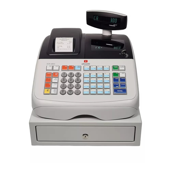
EXTERNAL COMPONENTS ECR 6800/6900 External Components 1. Customer display Power cord 2. Operator display Control lock 3. Keypad Printer compartment cover with receipt output window 4. Cash drawer 10. USB interface (on the ECR 6900 only) 5. Cash drawer lock 11. -
Page 10: Technical Specifications
1.2 TECHNICAL SPECIFICATIONS ECR 6800 Technical Characteristics Type: Electronic cash register with clamshell thermal printer, 40 departments, 8 clerks, up to 400 PLU settings and 3,000 line electronic journal Displays: Two 10-digit operator and client alphanumeric Vacuum Florescent Displays (VFD). -
Page 11: Safety Precautions
ECR 6920F Technical Characteristics Type: Electronic cash register with clamshell thermal printer, 99 departments, 15 clerks, up to 1,500 PLU settings, 70 tracking tables and 13,000 line electronic journal Displays: Two 10-digit operator and client alphanumeric displays. Symbols for error, change, subtotal, minus, total, foreign currency value, electronic journal memory nearly full or full, department number and item count shown Capacity:... -
Page 13: Unpacking And Setting Up The Cash Register
2. UNPACKING AND SETTING UP THE CASH REGISTER 2.1 STANDARD ACCESSORIES The cash register comes with the following items: • One black plastic journal winder spindle • One roll of standard paper tape • Three standard "AA" size batteries for the battery back-up system •... -
Page 14: Ecr 6800/6900 Keypad
2.2 ECR 6800/6900 KEYPAD receipt receipt feed clerk dept shift issue On/Off refund void #/NS card check ( - ) Price S.Total charge qty/ TOTAL time Fig. 2-1 2.2.1 KEYPAD FUNCTIONS - Opens the cash drawer without registering any - Advances the receipt or journal paper one line amount, for example, when changing cash for a non- feed;... -
Page 15: Ecr6800/6900 Control Lock And Key
- Multiplies [DEPARTMENT] or entries and - Used to enter a price manually for a PLU article. displays the current time in the REG and JRNL modes. - Subtracts an amount from the sales total. - Clears an entry made from the numeric keypad - Deletes the last item entered, and used for or with before finalizing a transaction with a... -
Page 16: Ecr 6920F Keypad
2.3 ECR 6920F KEYPAD 6 7 8 Fig. 2-3 2.3.1 ECR 6920F TRANSACTION KEYPAD FUNCTIONS - As the Guest key, enters the number of guests - Advances the receipt or journal paper one line at a determinate table. As the Tray TL-Tray key, provides feed;... - Page 17 - Price Look-Up key for defining the preset price - Enters a decimal point for defining product of a individual article, and assigning it to a specific quantities with decimals during sales transactions. department. - Numeric keys for entering amounts, - As the Review key, prints a proforma receipt departments, multiplication factors for repeat items, percentages and amounts to be subtracted or added.
-
Page 18: Ecr 6920F Caption Programming Keypad Functions
2.3.2 ECR 6920F CAPTION PROGRAMMING KEYPAD FUNCTIONS With the caption programming sheet installed in the keypad - After selecting the type of entity to program, skip to define the different programmable captions, and with to a specific item by entering its number on the numeric reference to figure 2-3: keypad and then press this key. -
Page 19: Printer Compartment
The cash register uses standard 2 1/4" (57 mm) thermal paper. 2.4.1 LOADING THERMAL PAPER ON THE ECR 6800/6900 1. Make sure the cash register is plugged into a grounded power outlet. - Page 20 57 mm. “ Fig. 2-7 6. Lower the clamshell mechanism and secure it in place by pushing it all the way down until it clicks into place. Fig. 2-8 7. Replace journal winder with wheel to right of compartment. 8. Pass the edge of the customer receipt through the receipt window on the compartment cover. 9.
- Page 21 10. Set the control switch to REG1 or REG2, press the [Feed] key and manually feed the paper into the slot until the paper catches and advances approximately six to ten inches above the print mechanism. Note: If the paper does not feed properly, check the alignment of the paper in the slot and/or for the straight edge on the end of the paper roll.
-
Page 22: Loading Thermal Paper On The Ecr 6920F
2.4.2 LOADING THERMAL PAPER ON THE ECR 6920F 1. Make sure the cash register is plugged into a grounded power outlet. 2. Unlock, open and remove the printer compartment cover , then remove the plastic journal winder spindle. Fig. 2-11 3. - Page 23 57 mm. “ Fig. 2-13 6. Lower the clamshell mechanism and secure it in place by pushing it all the way down until it clicks into place. Fig. 2-14 7. Replace journal winder with wheel to right of compartment. 8. Pass the edge of the customer receipt through the receipt window on the compartment cover. 9.
- Page 24 10. Set the control switch to REG1 or REG2, press the [Feed] key and manually feed the paper into the slot until the paper catches and advances approximately six to ten inches above the print mechanism. Note: If the paper does not feed properly, check the alignment of the paper in the slot and/or for the straight edge on the end of the paper roll.
-
Page 25: Cash Register Disassembly/Reassembly Procedures
Remove the printer compartment cover by rotating it upward in the direction of the arrow in the figure below and then lifting it off the case. ECR 6920F ECR 6800/6900 Fig. 3-1 • Remove the screws (1) that secure the machine case to the frame. - Page 26 • Push the upper part of the case with both hands, in the direction of the arrows shown in the figure below, to release the securing tabs (2) of the case from the machine frame. Fig. 3-3 Reassembly • To reassemble the case, proceed with the disassembly procedure in reverse order, making sure to properly fit the tabs of the case into their related slots as indicated by the arrows in the figure above.
-
Page 27: Mainboard/Operator-Client Display Assy Disassembly/Reassembly
MAINBOARD/OPERATOR-CLIENT DISPLAY ASSY DISASSEMBLY/REASSEMBLY • Remove the printer case from the machine frame as explained in the related section of this chapter, lift it gently and turn it to one side. Be careful to not detach the connection cables. • From the mainboard/operator-client display assy, disconnect the printer assy flat cable connectors (1), the transformer cable connector (2), the memory backup battery power supply cable connector (3), the keypad flat cable connectors (4), the USB port connector (5) and the serial port connector (6). -
Page 28: Mainboard Connectors
3.3.1 MAINBOARD CONNECTORS Fig. 3-5 1. Fuse 2. Transformer connector 3. Power supply connector 4. USB port connector 5. Serial port connector 6. Cash drawer sensor connector 7. Memory backup battery power supply connector 8. Keypad connectors 9. Control Key connector 10. -
Page 29: Interface Card Connectors (Ecr 6900/6920F Only)
3.3.2 INTERFACE CARD CONNECTORS (ECR 6900/6920F ONLY) Fig. 3-6 1. Serial interface 2. USB interface 3. USB cable from mainboard Y108540-8 Service Manual... -
Page 30: Keypad/Control Switch Assy Disassembly/Reassembly
KEYPAD/CONTROL SWITCH ASSY DISASSEMBLY/REASSEMBLY • Remove the printer case from the machine frame as explained in the related section of this chapter, lift it gently and turn it to one side. Be careful not to detach the connection cables. • Disconnect the Control Key cables (1) from the mainboard. - Page 31 • Remove the 15 screws (1) that secure the keypad. Fig. 3-8 Reassembly • To reassemble the keypad/control switch assy, follow its disassembly procedure in reverse order. Y108540-8 Service Manual...
-
Page 32: Operator Display/Client Display Assy Disassembly/Reassembly
OPERATOR DISPLAY/CLIENT DISPLAY ASSY DISASSEMBLY/REASSEMBLY • Disconnect the operator/client display connector (1) from the mainboard. • Disconnect the two client display connectors (2). Fig. 3-9 Service Manual Y108540-8... - Page 33 • Remove the two screws (3) that secure the operator/client display. Fig. 3-10 Reassembly • To reassemble the operator display/client display/keypad assy, follow its disassembly procedure in reverse order. Y108540-8 Service Manual...
-
Page 34: Journal Rewind Motor Disassembly/Reassembly
JOURNAL REWIND MOTOR DISASSEMBLY/REASSEMBLY • Remove the printer case from the machine frame as explained in the related section of this chapter, lift it gently and turn it to one side. Be careful not to detach the connection cables. • Disconnect the journal rewind motor cable connector (1) from the mainboard to remove the journal rewind motor (2). - Page 35 • Widen the two tabs (3) that hold the journal rewind motor (4) in the direction of the arrows in the figure below and remove the motor. Fig. 3-12 Reassembly • To reassemble the journal rewind motor, follow its disassembly procedure in reverse order. Remember to refit the rewind motor ground ring.
-
Page 36: Transformer Disassembly/Reassembly
TRANSFORMER DISASSEMBLY/REASSEMBLY • Remove the printer case from the machine frame as explained in the related section of this chapter, lift it gently and turn it to one side. Be careful to not detach the connection cables. • Make sure that fuse (1) is intact. If it is not, replace it. •... -
Page 37: Cash Drawer Electromagnet Disassembly/Reassembly
CASH DRAWER ELECTROMAGNET DISASSEMBLY/REASSEMBLY • Remove the cash drawer from the cash register. • Remove the printer case from the machine frame as explained in the related section in this chapter, lift it gently and turn it to one side. Be careful not to detach the connection cables. •... - Page 38 • Overturn the cash register again to its normal operating position and then, by bending the four tabs (3) of the frame, gently remove the upper part of the cash drawer in the direction of the arrows shown in the following figure. Fig.
-
Page 39: Troubleshooting And Electronic Circuitry
This chapter provides you with repair information and the circuitry diagrams for all the cash register models described in this manual (ECR 6800/6900/6920F). If the cash register malfunctions, refer initially to the following table and check the possible cause then proceed with the related corrective action. - Page 40 PROBLEM CAUSE/CHECKS CORRECTIVE ACTION The cash drawer does not • Make sure that the cash drawer is not • Unlock the cash drawer using open. locked. the keys provided with the cash register. • The cash drawer movement may be •...
-
Page 41: General Machine Circuitry
GENERAL MACHINE CIRCUITRY The cash register uses an 8-bit single chip microcomputer. The CPU has 128K bytes of internal Flash ROM and 6K bytes of internal RAM, and also uses a 512Kbyte external S-RAM. It uses a 10-digit Union Jack green fluorescent display and is equipped with a battery-backed up clock that keeps tracks of the month, day of the week, date, hours and minutes. -
Page 42: Power Supply Circuit
4.3 POWER SUPPLY CIRCUIT VDRW VDRW is generated using the AC input across pins 3 of CN11.This AC voltage is rectified by D18, a RL102-E diode. The resulting DC voltage is about +30V and is used by the drawer solenoid and the buzzer. VCC, VBB VCC is generated using the 12.8V AC input across pins 1 and 2 of CN11. -
Page 43: Power Supply Circuit Troubleshooting
-VPW The -VPW circuit uses a 26.5V AC across pins 4 and 5 of CN11. This AC voltage is rectified by D20, a RL102-E diode, and filtered by EC15. The circuit generating the -VPW uses the -30V applied to the collector of Q11, a 2SA1284D transistor, and base voltage controlled by ZD1. -
Page 44: Transformer Wiring Diagram
4.4 TRANSFORMER WIRING DIAGRAM AC 250VT 500mAL CT-89E AC13V 115V/2A 115V/2A AC24V Input Voltage AC26.7V 230V AC 50Hz AC4.8V Fig. 4-3 4.4.1 TRANSFORMER TROUBLESHOOTING PROBLEM CORRECTIVE ACTION Check the themal fuse; check for AC13.0V at pins 1 and 3, AC24.0V at pins 2 No power, no display. -
Page 45: Reset Circuit
4.6 RESET CIRCUIT The following four operations generate the reset signal: • External reset input via RESET pin. • Internal reset by watching timer program loop detection. • Internal reset by comparison of supply voltage and detection voltage of power-on-clear (POC) circuit. •... -
Page 46: Power Fail Circuit
4.7 POWER FAIL CIRCUIT Power Fail is detected by using the interrupting capability of low voltage circuit in the CPU. When compared to VBB and VLVI: VBB < VLVI when the voltage drops VBB > VLVI when the voltage rises, INTVLI is generated. The VLVI of power supply voltage can select the detect level by software and this model is set at 4.10V. -
Page 47: Winding Motor Circuit
4.8 WINDING MOTOR CIRCUIT The winding motor power is VPRN at Printer Power voltage. Printer Power voltage is on, and WIND_ON is High, when Q2 is ON as the winding motor is run. The cash register displays are controlled by main CPU bus signals P00, P01, P05-P07, P1,P2 and P3. The operator (front) and client (rear) displays are connected in parallel. -
Page 48: Display Circuit
The lower operator display and the client display are controlled by U1, ET16311 for controller. The upper operator display is controlled by U2. The ECR 6800 does not use this type of display. ECR 6800 - OPERATOR DISPLAY CIRCUIT... - Page 49 ECR 6900/6920F - OPERATOR DISPLAY CIRCUIT VF DU_a1 VF DU_a2 VFDU_b VFDU_c VFDU_d1 0.1uF VF DU_d2 VF DU_e VF DU_f VFDU_g VFDU_h VFDU_j VF DU_k VF DU_m S13/G16 VF DU_n SG1 4/GR1 5 VFDU_p SG15/GR1 4 VFDU_r SG16/GR13 VFDU_DP JUMPER SG17/GR12 ST B VF DU_com...
-
Page 50: Display Troubleshooting
Front is 14.0mm x 4.9mm Rear is 14.0mm x 4.9mm Operator/Client display The following figure shows the front display on the ECR 6900/6920F. The ECR 6800 has just one tube of the same display device. 1. Operator display 2. Client display Fig. -
Page 51: Connector Pins
4.10.1 CONNECTOR PINS Fig. 4-10 Parameter Symbol Minimum Typical Maximum Unit Operating Temp. ºC Storage Temp. ºC Filament Voltage 3.51 4.29 Grid Voltage 23.0 30.0 Vp-p Anode Voltage 23.0 30.0 Vp-p 2) Electrical Characteristics Parameter Sym. Test Condition Minimum Typical Maximum Unit Filament Current Ef=3.9 Vac... -
Page 52: Ecr 6800/6900 Keypad
4.11 ECR 6800/6900 KEYPAD The ECR 6800 and ECR 6900 keypad, shown in the following figure, consists of stroke keys. receipt receipt feed clerk dept issue On/Off shift refund void #/NS card check ( - ) Price S.Total charge qty/... -
Page 53: Keypad Circuit
The port data are encoded by U7 and U8 of 74HC138 and generate 15 stroke signals. The stroke keypad consists of a scan line (11) x return line (5) matrix, while the flat keypad consists of a scan line (15) x return line (6) matrix. ECR 6800/ECR 6900 stroke keypad Fig. 4-13 Y108540-8... -
Page 54: Ecr 6920F Keypad
4.12 ECR 6920F KEYPAD The ECR 6920F keypad, shown in the following figure, consists of stroke keys. Fig. 4-14 Key layout The following table provides the hexadecimal code corresponding to each keypad key. Fig. 4-15 4.12.1 KEYPAD TROUBLESHOOTING PROBLEM CORRECTIVE ACTION None of the keys work. - Page 55 ECR 6920F stroke keypad SCAN1 SCAN2 SCAN3 SCAN4 SCAN5 SCAN6 SCAN7 SCAN8 SCAN9 SCAN10 SCAN11 SCAN12 SCAN13 SCAN14 SCAN15 Fig. 4-16 Y108540-8 Service Manual 4-17...
-
Page 56: Drawer Circuit
4.13 DRAWER CIRCUIT The drawer is activated by signal P130 provided by the CPU. This signal is normally Low, and goes High to cause the drawer to open. When P130 is High, Q1 is on. Current flows through the transistor causing the collector to be held Low, near ground potential. Fig. -
Page 57: Buzzer Circuit
4.14 BUZZER CIRCUIT The buzzer is activated by signal P141 provided by the CPU. This normally Low signal goes High on 2 conditions: • On an error tone, P141 goes High until the error condition is cleared. • On a key pip tone, P141 goes high and then returns to its Low State. This pulse is of an extremely short duration. -
Page 58: Battery Circuit
4.15 BATTERY CIRCUIT VBB is the battery or VCC voltage. The batteries are connected to CN12 through the three diodes D26, D27 and D29. VBB goes to the CPU and external RAM for back-up voltage. Battery characteristics Type : SUM-3 x 3 pcs Voltage : 4.5V 2SA1036K EC16... -
Page 59: Memory Circuit
PROBLEM CORRECTIVE ACTION Memory backup does Check the voltage at point (1) indicated in the previous figure. not work. • If the reading is almost the same as the battery voltage, replace the mainboard. • If the reading is much less than the battery voltage or 0V, replace the battery unit. -
Page 60: Printer Circuit
4.17 PRINTER CIRCUIT Thermal printhead The cash register printer's thermal printhead consists of heating elements that are driven by the head drivers. The serial printing data input from the DAT IN pin is transferred to the shift register synchronously with the CLK signal, then stored in the latch register with the timing of the LATCH signal. Inputting the head activation signal activates the heating elements in accordance with the printing data stored in the latch register. -
Page 61: Printer Troubleshooting
Motor and thermal head drive timing Fig. 4-23 Division Printing Timing Chart 4.17.1 PRINTER TROUBLESHOOTING PROBLEM CORRECTIVE ACTION The printer does not print Check the voltage (DC +7.6V) at point (1) of the next figure: or does not feed paper. •... - Page 62 Fig. 4-24 4-24 Service Manual Y108540-8...
-
Page 63: Mpd78F0547 Microcomputer
4.18 µPD78F0547 MICROCOMPUTER The following table gives the port assignment of the µPD78F0547GK-8EU microcomputer. Legend: Open Drain Output POWER: Input pin for Power supply Built-in Pull-up resistor Port # Pin Specification Signal Signal Specification INITIAL PF(Backup) Pin Name Type Name Term. - Page 64 1 INTP0/EXLVI PU IF_SEL USB/RS232C SELECT 15 X1/OCD0A 9.8304MHz 14 X2/EXCLK/OCD0B 9.8304MHz 12 XT1 32.768kHZ 11 XT2/EXCLKS 32.768kHZ DRAW ER Darwer On GND-PD ( ク ロック ) 80 PCL/INTP6 PU BCR BCR_ON GND-PD 79 BUZ/BUSY0/INTP7 PU BUZZER Buzzer GND-PD 78 SCKA0# PU DSP_CLK Display Controller Clock 77 SIA0 PU DSP_CS2#Display Controller CS2...
-
Page 65: Serial Interface Circuit (Ecr 6800 Excluded)
4.19 SERIAL INTERFACE CIRCUIT (ECR 6800 EXCLUDED) BCR I/F TXD, RXD, RTS and CTS are UART communication parts from the CPU (U9). U5 (HIN232CB) is an RS232C trans- ceiver. The BCR power supply (DC +5.0V) is output from the CPU by the BCR-ON signal. - Page 66 USB I/F The USB I/F is controlled by the M38K07M4L (U1). The serial I/F is transferred to USB I/F in this circuit. This circuit is not used on the ECR 6800. Fig. 4-26 4-28 Service Manual Y108540-8...
-
Page 67: Serial Interface Circuit Troubleshooting
4.20.2 SOFTWARE VERSION The diagnostic software also prints its related version at the beginning of the test report. Note: The latest versions for the ECR6800/ECR6900/ECR6920F are indicated below. MODEL VERSION ECR 6800 ver. 1.02 ECR 6900 ver. 1.03 ECR 6920F ver. - Page 68 UPDATING STATUS DATE UPDATED PAGES PAGES CODE 02/2008 EDITION Y108540-8...