Table of Contents
Advertisement
Quick Links
Advertisement
Table of Contents

Related Manuals for Casio KL-1500


Summary of Contents for Casio KL-1500
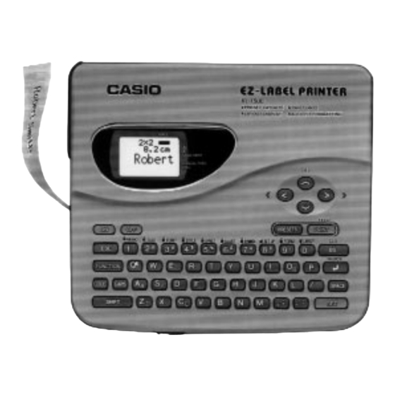
- Page 1 (without price) LABEL PRINTER KL-1500 (ZX-556) JUL. 1995 KL-1500...
-
Page 2: Table Of Contents
CONTENTS SPECIFICATIONS ---------------------------------------------------------------------------------------- 1 CLEANING THE PRINTER HEAD AND ROLLER ----------------------------------------------- 2 RESET OPERATION ------------------------------------------------------------------------------------- 2 BLOCK DIAGRAM --------------------------------------------------------------------------------------- 3 PRECAUTIONS ------------------------------------------------------------------------------------------- 4 ADJUSTMENT --------------------------------------------------------------------------------------------- 4 CIRCUIT DESCRIPTION -------------------------------------------------------------------------------- 5 LSI PIN FUNCTION -------------------------------------------------------------------------------------- 6 DIAGNOSTIC PROGRAM ------------------------------------------------------------------------------ 8 MESSAGES ---------------------------------------------------------------------------------------------- 10 SCHEMATIC DIAGRAM ------------------------------------------------------------------------------ 11 PARTS LIST ---------------------------------------------------------------------------------------------- 15... -
Page 3: Specifications
SPECIFICATIONS Input Keyboard layout : Typewriter (QWERTY) Character Types Alpha (English and other languages) : 151 Numbers : Symbols : Illustrations : Display Type : 48 X 32-dot liquid crystal display Number of columns : Character matrix : 16 X 16-dot Printing Type : 64-dot thermal transfer... -
Page 4: Cleaning The Printer Head And Roller
CLEANING THE PRINTER HEAD AND ROLLER 1 : Make sure to turn the power switch off. 2 : Open the tape cartridge compartment cover. 3 : Remove the tape cartridge. 4 : Use a cotton swab dipped in alcohol to clean the printer head and roller. 5 : Replace the tape cartridge and close the compartment cover. -
Page 5: Block Diagram
BLOCK DIAGRAM LCD 49 X 32 CD427-TS Comparator LCD driver LCD driver BA10339F-T1 HD44105H HD44102CH COMMON SEGMENT Chassis unit Keyboard Motor driver T6C37 BA12003 Thermal Head Reset IC RH5VL45AA-T1 VDD1 ( +5V for digital circuit) TC531001CF-15 (+9V for printer) VDD2 (+5V for RAM) VCON Q3 / Q4... -
Page 6: Precautions
PRECAUTIONS To prevent damage of the thermal head caused by static electricity when assembling the chassis ass'y into the unit, the following steps must be followed; 1 : Turn the power switch off. 2 : Discharge the capacitor C5(2200µF) on the PCB Z556-1. 3 : Connect the FPC of chassis ass'y into a connector CN4 of PCB Z556-1. -
Page 7: Circuit Description
CIRCUIT DESCRIPTION Setting the batteries or AC adaptor (see figure 7) When setting the batteries or AC adaptor, the voltage VDD2 is always applied to RAM and CPU since Q6 and IC5 are turned on. Power on sequence (see figure 7) When the power switch is turned on, PON signal is being H (PON = VDD2). -
Page 8: Lsi Pin Function
LSI PIN FUNCTION CPU (T6C37) : LSI1 Name I / O Function Read signal for memory devices Write signal for memory devices +5V source 4~15, 17~21 A0~A11, EA12~EA16 Address bus Ground (0V) source +5V source Chip enable signal for ROM Chip enable signal for RAM RNK1 Thermal head rank setting... - Page 9 LCD driver (HD44105H) : LSI201 N a m e I / O Function 1~12, 41~60 X1~X32 LCD drive output I / O I/O pin for 2 way shift register and shift data Ground 15, 16 FS1, FS2 Select frequency 17~19 DS1~DS3 Select display duty Oscillator...
-
Page 10: Diagnostic Program
DIAGNOSTIC PROGRAM Note : Make the reset operation after RAM check, because the RAM check break the data stored in RAM. Check item Operation Display N o t e (BOOT) Press ON while pressing Main menu 0 ALL 7 VP keys, SET + RETURN + 1 RAM 2 LCD... - Page 11 — 9 —...
-
Page 12: Messages
MESSAGES Message Meaning Action NO DATA! There is no data stored in memory. Store some data before trying to perform this operation. NOT ENOUGH There is not enough unused memory to Reduce the size of the data you are MEMORY! perform the operation. -
Page 13: Schematic Diagram
SCHEMATIC DIAGRAM PCB Z556-1 (1/2) — 11 —... - Page 14 PCB Z556-1 (2/2) — 12 —...
- Page 15 PCB Z-556-E4 (1/2) — 13 —...
- Page 16 PCB Z556-E4 (2/2) — 14 —...
-
Page 17: Parts List
PARTS LIST FOB Japan Item Code No. Parts Name Specification N.R.Yen Unit Price Z556-1 PCB ASS'Y LSI1 2011 9527 T6C37 LSI3 2012 0476 HN62321AFRM2 LSI2 2011 9520 CXK5864CM-10LL Monolithic IC 2114 2436 BA12003 Ceramic oscillator 2590 1435 EFOEC4004A4 1 10 2803 7821 Electrolytic capacitor RE3-16V222M-T2... - Page 18 FOB Japan Item Code No. Parts Name Specification N.R.Yen Unit Price R205,R206, 2796 0581 Chip resistor MCR10EZHG472 4 20 R208,R209 Chip resistor R201 2795 0826 MCR10EZHG683 1 20 Chip capacitor C206 2845 1925 MCH312F105ZP 1 10 C202 2845 2212 Chip capacitor MCH215A100DK 1 20 C201,C203,...
- Page 19 — 17 —...
- Page 20 — 16 —...
- Page 21 Chassis ass'y-1 — 19 —...
- Page 22 Chassis ass'y-2 — 20 —...
- Page 23 MA0800551A...