
Related Manuals for Endress+Hauser CleanFit P CPA 471


Summary of Contents for Endress+Hauser CleanFit P CPA 471
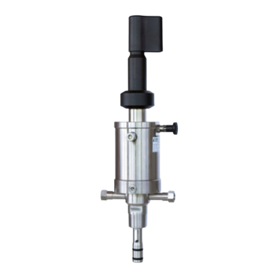
- Page 1 CleanFit P CPA 471 BA 217C/07/en/07.03 51502594 Retractable Process Assembly Operating Instructions Quality made by Endress+Hauser ISO 9001...
-
Page 3: Table Of Contents
CleanFit P CPA 471 Table of contents Safety instructions ....4 Technical data ....31 Designated use . -
Page 4: Safety Instructions
• Installation instructions • Local prevailing standards and regulations. Return If the assembly has to be repaired, please return it cleaned to the Endress+Hauser sales centre responsible. Please use the original packaging, if possible. Please enclose the completed Dangerous Goods sheet (copy the second last page of these Operating instructions) with the packaging and also the shipping documents. -
Page 5: Notes On Safety Icons And Symbols
CleanFit P CPA 471 Safety instructions Notes on safety icons and symbols Warning! This symbol alerts you to hazards. They can cause serious damage to the instrument or to persons if ignored. " Caution! This symbol alerts you to possible faults which could arise from incorrect operation. -
Page 6: Identification
Scope of delivery The scope of delivery comprises: • CleanFit assembly (ordered version) • Operating Instructions (english). If you have any questions, please contact your supplier or your Endress+Hauser sales centre responsible (see back page of these Operating Instructions). Endress+Hauser... -
Page 7: Product Structure
CleanFit P CPA 471 Identification Product structure Drive type and limit contact switches Manual (cannot be converted to pneumatic) Pneumatic without limit contact switches (suitable for retrofitting) Pneumatic with 2 pneumatic limit contact switches Pneumatic with 2 electric limit contact switches (max. 90 °C / 194 °F) Pneumatic with 2 electric Ex limit contact switches (max. -
Page 8: Installation
The original packaging offers the best protection. Also, keep to the approved ambient conditions (see "Technical data"). • If you have any questions, please contact your supplier or your Endress+Hauser sales centre responsible (see back page of these Operating Instructions). - Page 9 CleanFit P CPA 471 Installation > 15 ° > 15 ° > 15 ° > 15 ° C07-CPA471xx-17-07-00-xx-002.eps Fig. 3: Installation examples with recommended installation angle (glass electrodes) Tank Pipe bend Horizontal pipe " Ascending pipe Caution! • For all assemblies with stainless steel pressure cylinders, we recommend to use a flanged version when installing with inclined orientation.
- Page 10 Installation CleanFit P CPA 471 3.2.2 Dimensions mm / inch mm / inch Ø 30 / 1.18 Ø 58 / 2.28 mm / inch Ø 80 / 3.35 Ø 30 / 1.18 Ø 58 / 2.28 Ø 80 / 3.35 Ø...
-
Page 11: Installation Instructions
CleanFit P CPA 471 Installation 3.2.3 Process connections approx. 44 / 1.73 approx. 44 / 1.73 G / H mm / inch approx. 44 / 1.73 C07-CPA471xx-04-07-07-en-001.eps Fig. 7: CPA 471 process connections (short version, long version dimensions in brackets) G1 ¼... - Page 12 Installation CleanFit P CPA 471 3.3.2 Installing the assembly into the process Note! Depending on the process connection, please observe the following: • Check the flange seal between the flanges before installing the assembly. • The thread adapter nut of thread G 1¼ does not function as a seal. Therefore, simply tighten the thread adapter nut by hand.
- Page 13 CleanFit P CPA 471 Installation Limit position switches Pneumatic: 3/2 way valve Electric: inductive (NAMUR type) → 1 / BN → 2 / BU L– C07-CPA471xx-04-07-08-xx-001.eps Fig. 10: Limit position switches, left: pneumatic (1 = compressed air inlet, 2 = compressed air outlet)
- Page 14 Installation CleanFit P CPA 471 When the position "Service" is reached, the air applied to the inlet (1) is switched through and can be tapped at the outlet (2) (TopCal/ TopClean: hose no. ➅). Electric limit position switch connection Like the pneumatic limit position switches, the electric limit position switches also serve as control elements and determine the sequence of the individual steps.
- Page 15 CleanFit P CPA 471 Installation Gel sensors 1. Pull the retractable pipe as far as possible out of the assembly ("Service" position). 2. Turn the stop lock bolt through 90° so that the plastic grooves are located C07-CPA47xxx-19-07-00-xx-001.eps above the recesses (Fig. 14, A).
-
Page 16: Post-Installation Check
Installation CleanFit P CPA 471 " Caution! If turned in the opposite direction, the stop lock bolt does not engage. This could, however, loosen the sensor holder. The reason for this is adhesions on the lower part of the sensor holder. These can cause the sensor holder to get stuck, producing a counterforce when unscrewing the sensor holder. -
Page 17: Operation
CleanFit P CPA 471 Operation Operation First commissioning Before the first commissioning, make sure of the following items: • all seals are correctly seated (on the assembly and process connection) • the sensor is correctly installed and connected • the water supply line is correctly connected to the rinse connections (if fitted) •... -
Page 18: Pneumatic Operation
Operation CleanFit P CPA 471 Moving the assembly from the "Measuring" position to the "Service" position Release the stop lock bolt catch. Pull the retractable pipe out as far as possible ("Service" position). Lock the sensor holder with the stop lock bolt. -
Page 19: Maintenance
CleanFit P CPA 471 Maintenance Maintenance Warning! Risk of injury! Before starting maintenance work on the assembly, make sure that the process line and the tank are depressurised, empty and rinsed. Move the assembly to the "Service" position and lock the retractable pipe by the stop lock bolt. -
Page 20: Cleaning Agents
Maintenance CleanFit P CPA 471 Cleaning agents The selection of the cleaning agent is dependent on the degree and type of contamination. The most common contaminations and the suitable cleaning agents are listed in the following table. Type of contamination... -
Page 21: Accessories
CleanFit P CPA 471 Accessories Accessories Installation accessories ❑Filter set CPC 300 Water filter (dirt trap) 100 µm, complete, incl. angle bracket; order no. 51511336 ❑Pressure reducer kit complete, incl. manometer and angle bracket; order no. 51505755 ❑Welded fitting G1¼, straight, SS 1.4404 (AISI 316L);... -
Page 22: Limit Position Switches
Accessories CleanFit P CPA 471 Limit position switches ❑Set of pneumatic limit position switches (2 pieces); order no. 51502874 ❑Set of electric limit position switches, Ex and Non-Ex (2 pieces); order no. 51502873 Pneumatic throttle ❑Pneumatic throttle for the reduction of the assembly moving speed, order no. -
Page 23: Calibration Solutions
CleanFit P CPA 471 Accessories Calibration solutions 6.5.1 Technical buffer solutions, accuracy 0.02 pH, acc. to NIST/DIN ❑pH 4.0 red, 100 ml (0.026 US gal.), order no. CPY 2-0 ❑pH 4.0 red, 1000 ml (0.264 US gal.), order no. CPY 2-1 ❑pH 7.0 green, 100 ml (0.026 US gal.), order no. -
Page 24: Measuring, Cleaning And Calibration Systems
Accessories CleanFit P CPA 471 Measuring, cleaning and calibration systems ❑TopCal S CPC 300 Fully automatic measuring, cleaning and calibration system; Ex or Non-Ex, In-situ cleaning and calibration, automatic sensor monitoring, Ordering by product structure, see Technical Information ❑TopClean S CPC 30 Fully automatic measuring and cleaning system;... -
Page 25: Trouble-Shooting
CleanFit P CPA 471 Trouble-shooting Trouble-shooting Replacing damaged parts Warning! Damage to the assembly which affects the pressure safety must only be repaired by authorised technical personnel. After every repair and maintenance activity, suitable measures must be taken to test whether the assembly shows any signs of leaking. - Page 26 Trouble-shooting CleanFit P CPA 471 7.2.2 Replacing seals with process interrupt You can only replace the seals of the cylinder, of the rinse chamber and of the sensor guide when the process is interrupted and the assembly is dismounted from the process connection (Fig.
-
Page 27: Spare Part Kits
CleanFit P CPA 471 Trouble-shooting Spare part kits 10-1 14-3 10-2,10-3, 10-4 14-1 14-2, 14-3 C07-CPA471xx-09-07-06-xx-001.eps Fig. 23: Spare parts (all assembly versions) Note! Please, refer to the following table for the spare part kits ordering numbers acc. to the positions in Fig. - Page 28 Trouble-shooting CleanFit P CPA 471 Position Description and kit content Spare part kit order no. Retractable pipe for 120 mm (4.72 inch) gel electrodes 51503715 For assembly version: – pneumatic – short, immersion depth up to 101 mm (3.98 inch) Kit 471/472 short, pneumatic Retractable pipe for 225 mm (8.86 inch) gel electrodes...
- Page 29 CleanFit P CPA 471 Trouble-shooting Position Description and kit content Spare part kit order no. 10-1, Set of gaskets, dynamically loaded 51503728 10-2, 10-3 M12x1 stopper 51503733 For assembly version: – pneumatic, without limit switch 10 pieces Set of pneumatic limit switches...
-
Page 30: Return
– process connection: DN 50 dairy fitting – with G1/8 rinse fittings Return If the assembly has to be repaired, please return it cleaned to the Endress+Hauser sales centre responsible. Please use the original packaging, if possible. Please enclose the completed Dangerous Goods sheet (copy the second last page of these Operating instructions) with the packaging and also the shipping documents. -
Page 31: Technical Data
CleanFit P CPA 471 Technical data Technical data Environment Ambient temperature Ambient temperature not below 0 °C (32 °F). The maximum permissible temperature for electric limit position switches (NAMUR type) is 90 °C (194 °F). Process PA cylinder: max. 6 bar (87 psi) -
Page 32: Mechanical Construction
Technical data CleanFit P CPA 471 Mechanical construction Design, dimensions see chapter "Installation" Short version pH glass electrodes, gel 120 mm pH glass electrodes, KCl 225 mm pH ISFET sensors, gel, 120 mm Sensors pH ISFET sensors, KCl, 225 mm... -
Page 33: Index
CleanFit P CPA 471 Index Accessories Limit position switches ......22 Calibration solutions ..... . 23 Connection . - Page 34 CleanFit P CPA 471 Spare parts....... . 27 Splash protection cap ..... . . 15 Stop bolt lock .
- Page 35 'HFODUDWLRQ RI FRQWDPLQDWLRQ Dear customer, Because of legal determinations and for the safety of our employees and operating equipment we need this “Declaration of contamination” with your signature before your order can be handled. Please put the completely filled in declaration to the instrument and to the shipping documents in any case. Add also safety sheets and/or specific handling instructions if necessary.
- Page 36 Poland – Wroclaw Costa Rica – San Jose ❑ Sakura Endress Co. Ltd. ❑ Endress+Hauser Polska Sp. z o.o. Tel. (01) 88 05 60, Fax (01) 88 05 63 35 Euro-Tec S.A. Tel. (0422) 54 06 11, Fax (0422) 55 02 75 Tel.