Advertisement
Quick Links
INSTALLATION MANUAL
Applied Machines: 225i/205i; 236/226/206; 235/215/195
MFP: 23 ppm/22 ppm/21 ppm/20 ppm/19 ppm
Product Code: ACN2/ACN3; A8A5/A8A6; A3PE/A3R2
1. Pre-installation check items
■ General checks
• Refer to "Pre-installation check items" described
in the installation manual of the main body.
• Be sure to turn OFF the main power switch of
the main body and unplug the power cord before
starting the installation.
• Do not turn the power ON before the instruction.
■ Notice about this option
● Tools/jigs required for installation
• Stubby driver
■ Notice about description contents of the
manual
• This manual provides the illustrations of the ac-
cessory parts and machine that may be slightly
different in shape from yours.
In that case, instead of the illustrations, use the
appearance of your machine to follow the instal-
lation procedure. This does not cause any signif-
icant change or problem with the procedure.
• If none of the later steps instruct you to use the
parts including screw and cover that you re-
moved following the instructions described in this
manual, discard them.
2. Accessory parts
No.
Name
1. Automatic du-
plex unit
2. Transport guide
2019. 7 Printed in China
AD-509
Automatic Duplex Unit
Shape
Q'ty
1
1
E-1
No.
Name
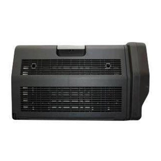
3. Cooling fan as-
sembly
4. Metal plate
5. Wire saddle
6. Screw A (3 x 8
mm)
7. Screw B (3 x 8
mm)
8. Installation
manual
WARNING
Keep this bag away from babies and chil-
dren. Do not use in cribs, beds, carriages,
or playpens.
The thin film may cling to nose and mouth
and prevent breathing. This bag is not a
toy.
Shape
Q'ty
1
2
1
1
3
1 set
A3PG-9950-03
1CA0835001
Advertisement

Related Manuals for Konica Minolta AD-509


Summary of Contents for Konica Minolta AD-509
- Page 1 AD-509 Automatic Duplex Unit INSTALLATION MANUAL Applied Machines: 225i/205i; 236/226/206; 235/215/195 MFP: 23 ppm/22 ppm/21 ppm/20 ppm/19 ppm Product Code: ACN2/ACN3; A8A5/A8A6; A3PE/A3R2 1. Pre-installation check items Name Shape Q’ty 3. Cooling fan as- ■ General checks sembly • Refer to “Pre-installation check items” described in the installation manual of the main body.
-
Page 2: Installation Procedures
<When the multi bypass tray is installed> 3. Installation procedures a) Remove the covers (left and right). (Three (1) Turn OFF the main power switch and unplug screws) the power cord from the power outlet. (2) Remove the indicated cover from the rear right side of the main body. - Page 3 c) Remove the four screws. (5) Remove the indicated cover from the cover re- moved in step (4). (One screw) Note: • If you remove the multi bypass tray in step (4), remove the indicated cover from the multi by- pass tray.
- Page 4 (6) Attach the supplied transport guide. (One sup- (8) Attach the two supplied metal plates. plied screw A) Note: Note: Make sure that the metal plates are in an upright If you remove the multi bypass tray in step (4), at- position.
- Page 5 (11) Tighten the two fixing screws of the automatic (16) Attach the supplied wire saddle. duplex unit. Note: • Tighten the screw on the reference side (indi- cated by the arrow) first. • Make sure the automatic duplex unit is not tilted.
- Page 6 (22) Remove the left cover from the main body. (Five screws) (23) Fit the two bosses into the holes, and attach the supplied cooling fan assembly to the main body. (Two supplied screws B) Boss (24) Connect the connector of the cooling fan as- sembly to the main body.